Resource Management in Satellite Networks part 4 doc
Bạn đang xem bản rút gọn của tài liệu. Xem và tải ngay bản đầy đủ của tài liệu tại đây (360.75 KB, 10 trang )
Chapter 1: INTRODUCTION TO SATELLITE COMMUNICATIONS 7
of significant signal impairment in the presence of bad wheatear conditions
(e.g., rain).
A transponder is a receiver-transmitter unit on a communication satellite.
It receives a signal from the Earth (uplink), manages it and retransmits it
back to Earth at a different frequency (downlink). A satellite has several
transponders in its payload. Two different types of transponders can be
distinguished as follows:
• Bent-pipe transponder (i.e., the transponder acts as a simple repeater).
On board, the signal is simply amplified and retransmitted, but there is
no improvement in the signal-to-noise ratio since also background noise is
amplified.
• Regenerating transponder: a transponder demodulates and decodes the
received signal, thus performing signal recovery before retransmitting it.
Since at some point base-band signals are available, other activities are
also possible, such as routing and beam-switching (in case of multi-beam
satellite antenna). Satellites with regenerating transponders and on board
processing capabilities can also employ Inter-Satellite Links (ISLs) with
other satellites of the same constellation, thus permitting the routing of
the signal in the sky.
It is important to provide here some interesting data for current state-of-
the-art GEO satellites.
• The Astra 1H satellite has 32 transponders with 24/32 MHz bandwidth
(total bandwidth of 1 GHz). Each transponder has a traffic capacity of
25-30 Mbit/s.
• The AmerHis satellite (51 transponders) has a hybrid payload with 4
channels, each with 36 MHz for a total capacity of 174 Mbit/s. Moreover,
there is a DVB-RCS transponder that can manage up to 64 carriers, each
with 0.5 Mbit/s and a DVB-S transponder with a capacity of 54 Mbit/s;
see the following Section 1.4 for more details on DVB-RCS and DVB-S
systems.
Tables 1.1 and 1.2 below provide a survey of some satellite communication
systems that are currently operational or planned [8],[9]; for the definition of
the different access techniques, please refer to the following Section 1.3.
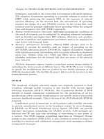
A typical satellite network architecture is shown in Figure 1.2, where we
can see the Earth station permitting the interconnection via a gateway to the
terrestrial core network.
Satellite communications are broadcast in nature. Hence, satellites do
not offer an adequate reliability from the security and privacy standpoint.
Practically, it is possible that a malicious user can hear what the others are
communicating. Therefore, it is necessary to adopt appropriate cryptography
algorithms to control network accesses and to protect transmissions.
Recently, the Broadband Global Area Network (BGAN) system has ac-
quired momentum to provide several services via Inmarsat-4 satellites (e.g.,
8 Giovanni Giambene
Fig. 1.2: Basic satellite network architecture.
System Orbit type,
altitude [km]
Services Access
scheme
Frequency
bands
GlobalStar 48 LEO, 1414 Mobile satellite system
voice and data services
Combined
FDMA &
CDMA
(uplink and
downlink)
Uplink:
1610.0-1626.5
MHz (L band)
Downlink:
2483.5-2500 MHz
(S band)
Iridium 66 LEO, 780 Mobile satellite system
voice and data services
FDMA/
TDMA -
TDD for
both uplink
and
downlink
Uplink:
1616-1626.5
MHz (L Band)
Downlink:
1610-1626.5 MHz
(L Band)
ICO
(new ICO)
12 MEO
(10 active),
10355 (changed
to 10390 km,
late 1998)
ICO is planning a family
of quality voice, wireless
Internet and other
packet-data services
FDMA/
TDMA -
FDD
Uplink:
1980-2010 MHz
Downlink:
2170-2200 MHz
(C/S bands)
Table 1.1: Description of the characteristics of the main satellite communication
systems (operational or planned) for non-GEO orbits.
telephony and ISDN calls; Internet/Intranet connection; SMS and MMS;
UMTS location-based services like information on maps or local travel in-
formation), firstly to fixed terrestrial user terminals, and secondly to mobile
terminals on planes, ships or land areas. BGAN satellites operate in the L
band. It is possible to adapt the transmission power, bandwidth, coding rate
and modulation scheme to terminal capabilities and to channel conditions,
in order to achieve high transmission efficiency and flexibility. The baseline
system allows communications from 4.5 to about 512 kbit/s to 3 classes
Chapter 1: INTRODUCTION TO SATELLITE COMMUNICATIONS 9
System Orbit type,
altitude [km]
Services Access
scheme
Frequency
bands
Spaceway 16 GEO
+ 20 MEO,
36000 - 10352
With Spaceway, large
businesses, telecommuters,
Small Office - Home
Office (SOHO) users and
consumers will have access
to two-way, high-data-rate
applications such as
desktop videoconferencing,
interactive distance
learning and Internet
services
Uplink:
FDMA/
TDMA
Downlink:
TDMA
Uplink:
27.5-30 GHz
Downlink:
17.7-20.2 GHz
Ka band
Thuraya 2GEO Voice telephony, fax,
data, short messaging,
location determination,
emergency services, high
power alerting
FDMA Uplink:
1626.5-1660.5 MHz
Downlink:
1525-1559 MHz
L/C bands
Eutelsat
(operator)
GEO satellites
(e.g., Hotbird 4,
Hotbird 6)
equipped with
the Skyplex
regenerating
transponder
Single digital TV
programme broadcasting,
digital radio broadcasting,
interactive multimedia
services and Internet
connectivity
Uplink:
DVB-RCS
(TDMA)
Downlink:
DVB-S
Uplink: 13.75, 14-
14.50, 29.50-30 GHz
Downlink: 10.70, 10.86-
12.75, 19.70-20.20 GHz
Ku and Ka band
Wildblue GEO
(Anik F2)
High-speed broadband
Internet access, satellite
television, distance
learning and telemedicine
Uplink:
TDMA
Downlink:
MF-TDMA
Uplink: 5.9-6.4 GHz
(C band), 14-14.5 GHz
(Ku band), 28.35-28.6
and 29.25-30 GHz
(Ka band)
Downlink: 3.7-4.2
(C band), 11.7-12.2
(Ku band), 18.3-18.8
and 19.7-20.2 GHz
(Ka band)
IPStar GEO Broadband access,
Intranet and VPN,
Broadcast/Multicast,
Video on Demand, Voice,
Leased Circuit/Trunking,
Video Conferencing
Uplink:
MF-TDMA
Downlink:
TDM/
OFDM
Uplink: 13.775-13.975,
14-14.5 GHz
Downlink: 10.95-11.2,
11.5-11.7, 12.2-12.75
GHz
Inmarsat 11 GEO
(10 active sats.):
4 Inmarsat-2,
5 Inmarsat-3,
2 Inmarsat-4
Simultaneous voice &
data, Internet & Intranet
content and solutions,
Video-on-demand,
videoconferencing, fax,
e-mail, phone and LAN
access
TDMA Uplink: 1.626-1.66,
1.98-2.025 GHz
Downlink: 1.525-1.559,
2.16-2.22 GHz
Table 1.2: Description of the characteristics of the main satellite communication
systems (operational or planned) for GEO orbits.
of portable terminals. The enhanced system (BGAN-X, BGAN Extension
project) has been developed to serve omni-directional and directional mobile
terminals, extending the classes from 3 to 11.
10 Giovanni Giambene
1.2 Basic issues in the design of satellite communication
systems
Satellite communications represent an attractive solution to provide broad-
band and multimedia services. To make the upcoming satellite network
systems fully realizable, meeting new services and application Quality of
Service (QoS) requirements, many technical challenges have to be addressed
as described below [1]-[5].
Round Trip propagation Delay (RTD)
RTD is the propagation delay along a link (back and forth). In the satellite
case, its value depends on the satellite orbit, the relative position of the user
on the Earth, and the type of satellite [1],[3],[5]. In particular, if the satellite
is regenerating, RTD involves a single hop from the Earth to the satellite and
back to the Earth; whereas, if the satellite is bent-pipe, RTD typically involves
a double hop (from Earth to satellite to Earth and back) since layer 2 control
functions are in the Earth station. In case of GEO regenerating satellites, RTD
varies in the range 239-280 ms. In particular, RTD is 239.6 ms for an Earth
station placed on the Earth equator in the point below the satellite; whereas,
RTD is about 280 ms for an Earth station placed at the edge of the satellite
coverage area (i.e., seeing the satellite with the minimum allowed elevation
angle). Note that RTD can be also referred to an end-to-end connection,
involving many links (the satellite type is not relevant for such RTD). In the
GEO case, this end-to-end RTD value (between a message transmission and
the reception of the relative reply) varies from 480 to 558 ms; this value can
increase due to processing, queuing and on-board switching operations.
The RTD values increase with the satellite orbit altitude and reduces
with the elevation angle. LEO and MEO satellites are situated at low
altitudes, so they allow lower RTD values than GEO. High RTD values
cause several problems for both interactive and real-time applications (e.g., an
evident and troublesome echo in phone calls); moreover, also reliable transport
layer protocols can experience problems since the end-to-end delay loop is
dominated by the propagation delay contribution due to the satellite segment.
The maximum RTD value (RT D
max
) for a given satellite constellation also
depends on the minimum elevation angle (mask angle), i.e., the elevation angle
at the edge of coverage. The RTD
max
characteristics for LEO satellite systems
are described in Figure 1.3.
Atmospheric effects
The effects of atmosphere (subdivided in troposphere and ionosphere) can be
summarized as follows [2]:
Chapter 1: INTRODUCTION TO SATELLITE COMMUNICATIONS 11
Fig. 1.3: RTD
max
level curves in ms for LEO satellite constellations in the plane
Minimum elevation angle [in degrees] versus LEO satellite constellation altitude [in
km].
• Atmospheric gasses. Oxygen (dry air) and water vapor determine an
attenuation of the electromagnetic signal that depends on the transmission
frequency: below 10 GHz, it is possible to ignore the influence of the
atmospheric gasses; between 10 and 150 GHz, molecular oxygen dominates
the total attenuation (in this region the local attenuation peaks are at 22.3
GHz -Ka band- and at 60 GHz -V band-, respectively due to water vapor
and molecular oxygen); whereas, above 150 GHz, the effect of water vapor
is dominant.
• Rain attenuation. This type of attenuation is the most significant one
among the atmospheric effects. There are several prediction models to
establish the quantity of rain fall attenuation, depending on some pa-
rameters, such as the rain fall rate probability distributions, the slant
path length, and the rain height. With these parameters it is possible
to characterize the level of rain and the relative attenuation (e.g., rain,
widespread rain, showery rain, rainstorm, etc.).
• Fog and clouds. The attenuation effects of fog and clouds are not so impor-
tant for systems operating below 30 GHz; while, they are significant above
30 GHz. This type of attenuation is related to frequency, temperature and
liquid water density (expressed in g/m
3
). Empirical models (one of them
is recommended by ITU) are used to predict fog and clouds attenuation.
12 Giovanni Giambene
• Scintillation. This is a phenomenon that affects satellite communication
systems operating above 10
◦
elevation angle and below 10 GHz (Ku band).
This effect consists of small and quite rapid fluctuations due to some
irregularities in the troposphere refractive index. As for the reception in
a mobile environment, the signal can be faded and enhanced by these
fluctuations.
Channel losses
In satellite networks, Bit Error Rate (BER) is very high, due to the above-
mentioned atmospheric effects. The quality of the satellite link can be subject
to rapid degradation that can cause long sequences of erroneous bits. These
burst errors cause an on-off behavior for the channel. With the use of Forward
Error Correction (FEC) codes (e.g., Reed-Solomon codes, convolutional codes,
etc.), it is possible to reduce remarkably BER at the expenses of a lower
information bit-rate (i.e., part of the available capacity is spent in sending
redundancy bits).
Satellite lifetime
Satellites have an average life span due to the components’ ageing process, the
effect of radiations, the necessity of new components, etc. GEO satellites have
a lifetime in the range of 10-15 years. MEO satellites have an operational
period of 10-12 years. Finally, LEO satellites are efficient between 5 and 8
years, mainly due to radiation effects.
1.3 Multiple access techniques
Multiple access is the ability of a large number of Earth stations to simul-
taneously interconnect their respective multimedia traffic flows via satellite
[1],[10]. These techniques permit to share the available capacity of a satellite
transponder among several Earth stations. The most common techniques are:
• Frequency Division Multiple Access (FDMA),
• Time Division Multiple Access (TDMA),
• Code Division Multiple Access (CDMA),
• A mix of the above schemes (e.g., combining TDMA and CDMA or FDMA
and TDMA).
These different multiple access techniques are surveyed below. Note that
another form of multiple access is also allowed in the presence of a multi-
spot-beam antenna on the satellite. This technique is called Spatial Division
Multiple Access (SDMA) [11]. With a multi-spot-beam antenna, some beams
may re-use the same frequencies, provided that the cross-interference (due to
Chapter 1: INTRODUCTION TO SATELLITE COMMUNICATIONS 13
beam radiation pattern side-lobes) is negligible. Usually, beams separated by
more than two or three half-power beam-widths can use the same frequen-
cies; this frequency reuse technique permits increasing the utilization of air
interface resources.
FDMA
In FDMA, the total bandwidth is divided into equal-sized parts; an Earth
station is permanently assigned with a portion around a carrier or carriers.
FDMA requires guard bands to keep the signals well separated. The traffic
capacity of an Earth station is limited by its allocated bandwidth and the
Carrier power-to-Noise power ratio (C/N). The carrier frequencies and the
bandwidths assigned to all the Earth stations constitute the satellite’s fre-
quency plan. FDMA requires the simultaneous transmission of a multiplicity
of carriers through a common Traveling-Wave-Tube Amplifier (TWTA) on the
satellite. The TWTA is highly non-linear (it produces maximum output power
at the saturation point, where the TWTA is operating in the non-linear region
of its characteristics) and the Inter-Modulation (IM) products generated by
the presence of multiple carriers produce interference. The only way to reduce
IM distortion is to lower the input signal level, so that the TWTA can operate
in a more linear region. For a given carrier, the dB difference between the
single-carrier input power level at saturation and the input power level for that
particular carrier in multi-carrier FDMA operations is called input backoff.
The corresponding output transmission power reduction in dB is called output
backoff.
TDMA
In TDMA, the total bandwidth is usually divided into time slots, organized
according to a periodic structure, called frame. Each slot is used to convey
one packet. Hence, TDMA is well suited for packet traffic. In TDMA uplink
transmissions, Earth stations take turns sending bursts through a common
satellite transponder. As for TDMA downlink transmissions from a satellite,
only one carrier is used. Hence, TDMA provides a significant advantage, since
it permits a transponder’s TWTA to operate at or near saturation, thus
maximizing downlink C/N. However, interference is not totally eliminated,
since it is present in the form of inter-symbol interference that must be
minimized by means of appropriate filtering. TDMA is easy to reconfigure
for changing traffic demands, it is robust to noise and interference and allows
mixing multimedia traffic flows.
While in TDM (Time Division Multiplexing) all data come from the same
transmitter and the clock and time frequencies do not change, in TDMA
each frame contains a number of independent transmissions. Each station has
to know when to transmit and must be able to recover the carrier and the
data synchronization for each received burst in time to sort out all desired
14 Giovanni Giambene
base-band channels. This task is not easy at low C/N values. A long preamble
is generally needed, which decreases system efficiency.
A group of Earth stations, each at a different distance from the satellite,
must transmit individual bursts of data in such a way that bursts arrive
at the satellite in correspondence with the beginning of the assigned slots.
Stations must adjust their transmissions to compensate for variations in
satellite movements, and they must be able to enter and leave the network
without disrupting its operation. These goals are accomplished by exploiting
the TDMA organization in frames, which contain reference bursts that permit
establishing absolute time for the network.
Reference bursts are generated by a master station on the ground in
a centralized-control satellite network. Each burst starts with a preamble,
which provides synchronization and signaling information and identifies the
transmitting station. Reference bursts and preambles constitute the frame
overhead. The smaller the overhead, the more efficient the TDMA system,
but the greater the difficulty in acquiring and maintaining synchronism.
Time access to the satellite link can be managed either in centralized or in
distributed mode. Centralized control is generally more robust. On the other
hand, the distributed control is more responsive to traffic variations, since it
allows an update in one RTD.
CDMA
The signals are encoded, so that information from an individual transmitter
can be detected and recovered only by a properly synchronized receiving
station that knows the code used (“scrambling code”) for transmissions.
In a decentralized satellite network, only the pairs of stations that are
communicating need to coordinate their transmissions (i.e., they need to
use the same code). The concept at the basis of CDMA is spreading the
transmitted signal over a much wider band (Spread Spectrum). This technique
was developed as a jamming countermeasure for military applications in the
1950s. Accordingly, the signal is spread over a band PG times greater than
the original one, by means of a suitable ‘modulation’ based on a Pseudo Noise
(PN) code. PG is the so-called Processing Gain. The higher the PG, the higher
the spreading bandwidth and the greater the system capacity. Suitable codes
must be used to distinguish the different simultaneous transmissions in the
same band. The receiver must use a synchronous code sequence with that of
the received signal, in order to de-spread correctly the desired signal. There
are two different techniques for obtaining spread spectrum transmissions:
• Direct Sequence (DS), where the user binary signal is multiplied by the PN
code with bits (called chips) whose length is basically PG times smaller
that that of the original bits. This spreading scheme is well suited for
Binary Phase Shift Keying (BPSK) and Quadrature Phase Shift Keying
(QPSK) modulations.
Chapter 1: INTRODUCTION TO SATELLITE COMMUNICATIONS 15
• Frequency Hopping (FH), where the PN code is used to change the
frequency of the transmitted symbols. We have a fast hopping if frequency
is changed at each new symbol, whereas a slow hopping pattern is obtained
if frequency varies after a given number of symbols. Frequency Shift Keying
(FSK) modulation is well suited for the FH scheme.
Comments and comparisons among the access techniques
The drawback of TDMA is the need to size Earth stations for the entire
system capacity (transponder bandwidth), even though the single terminal
uses a small portion of that. An interesting solution is given by the hybrid
combination of Multi-Frequency (MF) with TDMA systems, which takes some
advantages of both FDMA and TDMA [12]. In MF-TDMA the transponder
spectrum is divided into several carriers, thus allowing the sizing of the station
on a narrower bandwidth. Each carrier, in turn, is shared in TDMA mode.
The transmission of the traffic occurs in time slots that may belong to different
carriers. When a single modulator is used, slots of a transmission need not to
overlap in time (i.e., simultaneous transmissions on different frequencies are
not allowed). The MF-TDMA technique efficiently supports traffic streaming,
while maintaining flexibility in capacity allocation.
1.4 Radio interfaces considered and scenarios
Different standardized air interfaces are available for satellite communication
systems. In particular, this book is focused on both the satellite extension
of the terrestrial Universal Mobile Telecommunications System (UMTS) [1]
and the Digital Video Broadcasting via Satellite (i.e., DVB-S, DVB-S2 and
DVB-RCS) [13]-[16]. In addition to this, scenarios have been considered that
combine together different aspects, such as: satellite orbit type, mobile or fixed
users, adopted air interface. In particular, the following scenarios have been
identified:
• Scenario 1: Satellite-UMTS (S-UMTS) for mobile users through GEO
bent-pipe satellite;
• Scenario 2: DVB-S/DVB-RCS for fixed broadband transmissions via
GEO bent-pipe satellite;
• Scenario 3: LEO constellation with regenerating satellites for the provi-
sion of multimedia services to mobile users adopting handheld devices.
1.4.1 S-UMTS
Satellite communication systems should be able to provide to mobile users the
same access characteristics of the terrestrial counterparts. We refer here to
the provision of 3
rd
Generation (3G) mobile communication services through
16 Giovanni Giambene
satellites. In particular, the interest is on the extension of the UMTS standard
to the satellite context (S-UMTS). The ETSI S-UMTS Family G specification
set aims at achieving the satellite air interface fully compatible with the
terrestrial W-CDMA-based UMTS system [17]-[20]. S-UMTS will not only
complement the coverage of the Terrestrial UMTS (T-UMTS), but it will
also extend its services to areas where the T-UMTS coverage would be either
technically or economically not viable.
The satellite radio access network of the S-UMTS type should be connected
to the UMTS core network via the Iu interface [1],[21]. S-UMTS is expected to
be able to support user bit-rates up to 144 kbit/s that appear to be sufficient
to provide multimedia services to users on the move, employing typically small
devices [22].
With the evolution of terrestrial 3G systems standardization, the High
Speed Downlink Packet Access (HSDPA) has been defined to upgrade current
terrestrial 3G (W-CDMA) systems to provide high bit-rate downlink trans-
mission to users. HSDPA’s improved spectrum efficiency enables users with
downlink speeds typically from 1 to 3 Mbit/s. Hence, capacity-demanding
applications are possible, such as video streaming. The mandatory codec for
streaming applications is H.263, with settings depending on the streaming
content type and the streaming application.
The novel HSDPA air interface is based on the application of Adaptive
Coding and Modulation (ACM) and multi-code operation depending on the
channel conditions (forward link) that are feed back by the User Equipment
(UE) to the Node-B. The interest in this book is on the study for the possible
extension of HSDPA via satellite, as an upgrade of S-UMTS specifications. In
this case, all resource management functions for the S-HSDPA air interface are
managed by the base station (i.e., Node-B) on the Earth that is directly linked
to the Radio Network Controller (RNC) that operates as a gateway towards
the core network. More details on this study will be provided in Chapter 5.
1.4.2 DVB-S standard
DVB-S has been designed for primary and secondary distribution in the bands
of FSS and BSS [13]. Such systems should be able to provide direct-type
services (Direct-To-Home, DTH) both to the single consumer having an
integrated receiver-decoder, to systems with a collective antenna and to the
terminal stations of cable-TV. The frequency bands for feeder and user links
may occupy Ku/Ku, Ku/Ka and K/Ka bands.
Below the transport layer and the IP layer the Multi Protocol Encapsula-
tion (MPE) provides segmentation & reassembly functions for the generation
of Moving Picture Experts Group 2 - Transport Stream (MPEG2-TS) packets
of 188 bytes (fixed length). A TCP header of 20 bytes, an IP header of
20 bytes and an MPE header + CRC trailer of 12 + 4 bytes are added
to packets from the application layer; the resulting blocks are fragmented
in payloads of MPEG2-TS packets. All the data flows transported in single