Lead–acid batteries with polymer-structured electrodes for electric-vehicle applications potx
Bạn đang xem bản rút gọn của tài liệu. Xem và tải ngay bản đầy đủ của tài liệu tại đây (6.39 MB, 11 trang )
Ž.
Journal of Power Sources 78 1999 220–230
Lead–acid batteries with polymer-structured electrodes for
electric-vehicle applications
M.L. Soria
)
, J. Fullea, F. Saez, F. Trinidad
´
() ( )
S.E.A. Tudor, Research Laboratory Exide Europe , Carretera Nacional II, km 42 P.O. Box No. 2 , E-19200 Azuqueca de Henares, Guadalajara, Spain
Abstract
Some years ago a consortium of enterprises and a university from different European countries and industrial sectors was established
to work together in the development of lighter lead–acid batteries for electrical and conventional vehicles with new innovative materials
and process techniques, with the final goal of increasing the energy density by means of a battery weight reduction. Its main idea was to
Ž
substitute the heavy lead alloy grids mechanical support of the active masses and collectors of the current produced during the charge
.Ž.
and discharge reactions by lightweight metallised polymeric network structures PNS with reduced mesh dimensions in comparison to
conventional grids. The network was then coated with conductive materials and corrosion resistant layers to conduct the current flow. In
this paper, the electrode characteristics and the design features of the batteries prepared in the project will be described and their electrical
performance presented. q 1999 Elsevier Science S.A. All rights reserved.
Keywords: Lead acid batteries; Electric vehicle; Polymeric support; Electroplated materials; Manufacturing processes; Electrode and cell testing
1. Introduction
The increasing concern for the environment and the
pollution problems caused by the ICE vehicles, specially in
the big cities, have led to a worldwide interest for the
development of efficient electric and hybrid vehicles. The
battery, as autonomous energy storage system, is a key
element in the operation of the electric vehicles, due to its
great influence on the final cost, range and performance of
the vehicle. The characteristics of the batteries available in
the market today impose hard restrictions to the perfor-
mance of the electric vehicles.
Most of the electric vehicles in the market are trac-
tioned by lead–acid batteries, although they store less
energy per unit weight than the other systems. This fact is
due to the main advantages of this system: availability, low
cost, satisfactory power density, safety and the established
infrastructure for battery manufacturing and recycling.
However, its main disadvantages are its low specific
energy and cycle life, when compared to other battery
Ž.
systems alkaline, lithium, etc. .
Some years ago, a consortium of enterprises and a
university from different European countries and industrial
sectors was established in order to work together in the
)
Corresponding author
development of lighter lead–acid batteries for electrical
and conventional vehicles. The project has been partially
funded by the European Commission and the Swiss
Ž.
Federal Office for Education and Science OFES under
the Brite-EuRam II Programme.
The objective of the project was to develop advanced
lightweight lead–acid batteries with new innovative mate-
rials and process techniques, with the final goal of increas-
ing the energy density by means of a battery weight
reduction, and continuous processes for electrode manufac-
turing to allow the achievement of a cost competitive
product.
The main idea was to substitute the heavy lead alloy
Ž
grids mechanical support of the active masses and collec-
tors of the current produced during the charge and dis-
.
charge reactions by the best-suited material for each
function: high strength fibre material for the support of the
active mass and copper for the current collector function.
The new grid has therefore been developed as a lightweight
Ž.
metallised polymeric network structure PNS with a high
surface area due to the reduced mesh dimensions in com-
parison to conventional grids. The network was then coated
with conductive materials and corrosion resistant layers to
conduct the current flow.
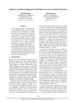
Fig. 1 shows a cross-section of the polymeric network
structure electrode, with indication of the partners involved
in the development of the different layers.
0378-7753r99r$ - see front matter q 1999 Elsevier Science S.A. All rights reserved.
Ž.
PII: S0378-7753 99 00029-4
()
M.L. Soria et al.rJournal of Power Sources 78 1999 220–230 221
Fig. 1. Cross-section of PNS electrodes.
This paper covers a part of Tudor’s work in the project,
dealing with the testing of PNS grids and electrodes and
the modification of the battery manufacturing processes.
2. Grid testing
Different open mesh polymer network structures have
been developed during the project, and, after copper and
lead plating, tested mechanically and electrically as battery
grids, in comparison with conventional gravity casted and
expanded lead grids.
The following parameters have been studied, defining
in some cases special testing procedures:
.
Average grid weight and weight distribution.
.
Electric conductivity by means of the resistance map
of the grids, in comparison with conventional grid designs,
gravity cast and expanded.
.
Distribution of conductive materials, by means of the
chemical analysis of different positions in the grid samples
and the observation and measurement of the metallic
layers with a metallographic microscope.
.
Adherence of the metallic layers to the polymeric
substrate when the grid is subjected to an external stress
and deformation. No variation of the grid electrical resis-
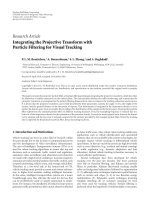
Fig. 2. Poor welding connection lug-substrate.
()
M.L. Soria et al.rJournal of Power Sources 78 1999 220–230222
Fig. 3. Optimised lug-substrate connection with pre-tinned welding.
tance has been observed after winding the samples around
glass cylinders with different diameters. These results indi-
cate that the copper layer is ductile and shows enough
adherence to the substrate, to avoid the formation of cracks
which would reduce the grid conductivity.
.
Mechanical strength: Tensile strength tests have
shown the improved behaviour of the PNS grids when
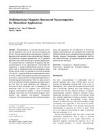
Fig. 4. Pretinning of PNS grids: long immersion time.
compared with conventional samples, and the high quality
of the lug welding process.
.
Thermal stability of electrodes under low pressure
conditions, by the measurement of the elongation and
thickness decrease when the grids are subjected to com-
Ž
pression under extreme battery working temperatures up
.
to 808C.
.
Chemical stability of the lead protective layers by
immersion of the grids in sulphuric acid solutions with
different specific gravity values.
Fig. 5. Pretinning of PNS grids: optimised conditions.
()
M.L. Soria et al.rJournal of Power Sources 78 1999 220–230 223
Fig. 6. COS welding of PNS grids under high temperature conditions:
partial melting of PNS substrate.
During the project, new grids including modifications in
the polymer substrate, knitting design and copper and lead
electrodeposition conditions, copper content and improved
electrical characteristics through the insertion of conduc-
tive filaments have been characterised. In general, an
important weight reduction has been achieved, with an
improvement in conductivity and mechanical properties
through a better distribution of the metallic layers and the
knitting designs.
The optimised PNS grids developed in the project show
Ž.
lower weight than standard grids approximately 1r3 with
the same conductivity properties, proper weight homogene-
ity in the same batch and metal distribution on the grid
surface, good adhesion of the metallic layers, enough
thermal stability under pressure for the application and
higher mechanical strength than standard grids.
3. Modification of the manufacturing processes
Several battery manufacturing processes had to be
adapted to the characteristics of the new grid materials.
A lug fixing process has been developed to provide the
PNS grid with a compact metallic contact for good current
transfer without damaging the polymeric structure during
the welding process. The lug is a critical part of the
electrode because it works as collector for the current
flowing from the electrode to the battery terminals. The
development of a proper lug fixing process was important
for the whole performance of the battery, in order to
provide the lowest voltage drop under high current drains.
The whole process was characterised by the following
features:
Ø A pre-tinning step of the copper plated PNS electrodes
with a low-melting alloy, which favours the welding
process carried out subsequently.
Fig. 7. Strap-lug welding under optimised conditions: general and detailed view.
()
M.L. Soria et al.rJournal of Power Sources 78 1999 220–230224
Table 1
Characteristics of the different grid designs
PNS type Mesh size Co-knitted Cu filament Observations
A1mm= 1mm No
B3mm=1 mm alternating 1 mm= 1 mm Yes
C3mm=3 mm Yes Knitting T-1
D3mm= 3 mm Yes Enhanced Cu density in the lug region
E3mm= 3 mm Yes Knitting T-2
Ø The lug material was a low melting point lead alloy
strip.
Ø A special lug design was used to avoid the polymer
deterioration during the plate group completion.
Ø Lug welding under high pressure and low temperature
conditions.
The quality of the lug fixing has been studied by means
of metallographic observation and conductivity measure-
ments. Figs. 2 and 3 show, respectively a poor welding
connection between the lug and the substrate, without the
pre-tinning step, and the high welding quality obtained
with the optimised process conditions defined in the pro-
ject.
The process conditions of the pre-tinning step are also
critical: Fig. 4 shows that long immersion times can lead to
the partial melting of the polymer and Fig. 5, the proper
process conditions.
New actiÕe masses with lower density and higher pene-
tration values, adapted to the closer mesh structure, have
led to a higher active material efficiency, taking advantage
of the three-dimensional structure of the new grid. Curing
and formation conditions have also been tested, in order to
achieve a satisfactory performance in the cycle life test,
together with improved capacity and high rate performance
due to the higher porosity.
Cast on strap welding of the plates has been adapted
for the group completion. As the thermal characteristics of
PNS and conventional lugs are different, it has been
necessary to study the process conditions in order to obtain
a good welding quality for both types of plates simultane-
ously.
The temperatures of both the mould and molten lead
turned out to be critical: a too low temperature leads to a
bad welding, with poor contact between the strap and the
plate lugs and a too high temperature produces the melting
Ž
and fracture of the PNS lug due to its polymeric core Fig.
.
6 . The optimised process conditions were finally estab-
lished and used in the preparation of plate groups for
electrical testing. Fig. 7 shows a general and detail view of
the welding area of PNS grids.
4. Test of single electrodes and plate groups
Electrodes prepared along the project with the different
PNS materials and conductive layers developed have been
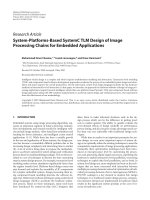
Fig. 8. Negative mass utilisation at different discharge rates.
()
M.L. Soria et al.rJournal of Power Sources 78 1999 220–230 225
Fig. 9. Specific energy increase: PNS vs. conventional EV.
mechanically and electrically tested. Mechanical testing
showed good active material retention after a strong vibra-
tion test.
Electrical testing was aimed to study the effect of the
mesh size and the copper distribution on the active mate-
rial utilisation at different discharge rates and tempera-
tures. Tests have been performed with single electrodes
and as plate groups and real cells, comparing the perfor-
mance of PNS grids with standard plates for EV applica-
tions.
Table 1 shows the characteristics of the different PNS
materials tested along the project. In all cases the total
copper content per grid was 10" 0.5 g and the lead
content was calculated according to a layer thickness of 50
mm.
4.1. Electrode testing
The performance of negative electrodes has been tested
in single cells with two positive plates and one negative
Ž.
plate PNS and conventional grids for EV application . In
all cases, the cell was flooded, and the positive plates were
conventional EV plates. In these conditions, the cell per-
formance would be limited by the negative plates under
study.
Fig. 10. Negative active material utilisation of PNS and standard plates at 190 Arkg.
()
M.L. Soria et al.rJournal of Power Sources 78 1999 220–230226
Fig. 11. Negative active material utilisation of PNS and standard plates at 380 Arkg.
Six cells were assembled with conventional negative
plates, and six with PNS type A negative plates. All of
them had the same grid weight and dry paste weight, so
that they were directly comparable. The cells were tested
Ž.
at different discharge rates from Cr8 to 8C and different
temperatures, obtaining the following results.
B Evolution of voltage vs. duration of the discharge:
The shape of the voltage evolution curve is very similar
for both types of plates, but the duration time for PNS type
A plates is larger than for conventional grids in the same
conditions.
B Negative active material utilisation vs. discharge rate
Ž.
Fig. 8 : The PNS type A plates show a better active
material utilisation in the whole range from Cr8to8C
discharge rates in discharges down to 1 Vrcell.
Ž.
B Specific energy increase Fig. 9 : The highest in-
crease in energy for the PNS type A grids vs. the conven-
Ž
tional grids is in the high discharge rate area 2C, 4C and
.
8C with a 50% increase.
B Influence of temperature: Another important parame-
ter tested was the influence of temperature in the specific
energy. The increase in negative active material utilisation
energy for PNS type A plates with respect to the conven-
tional plates is higher at temperatures under 08C, obtaining
the better results at the higher discharge rates. The evolu-
tion of negative active material utilisation vs. temperature
Fig. 12. Negative active material utilisation of PNS and standard plates at 760 Arkg.
()
M.L. Soria et al.rJournal of Power Sources 78 1999 220–230 227
Fig. 13. Negative active material utilisation of PNS and EV plates at different temperatures.
is represented in Figs. 10–12, for discharges at 190, 380
and 760 Arkg, respectively.
The great difference observed between PNS type A and
conventional grids is attributed to the mesh size: 1 mm= 1
mm for the former and 11 mm= 8 mm for the latter. The
influence of the grid geometry on the active mass utilisa-
wx
tion follows a well-known pattern 1 : the smaller the mesh
size, the higher the active mass utilisation. But, on the
other hand, with conventional lead grids, a small mesh size
involves an important increase in the grid weight. In the
present case, with polymeric electrodes, it is possible to
reduce the size of the mesh while maintaining a low grid
weight.
4.2. Test of electrodes as 3r2 groups
Cells with negative PNS type B plates and with nega-
tive conventional plates were assembled with similar total
weights. In Fig. 13, the negative active material utilisation
Ž
vs. the rate of discharge for two temperatures 258C and
.
y108C is represented. In all conditions tested, the PNS
type B plates showed better results than conventional
plates.
Fig. 14. Capacity of PNS and EV negative plates at different discharge regimes.
()
M.L. Soria et al.rJournal of Power Sources 78 1999 220–230228
Fig. 15. Specific energy increase of PNS vs. conventional EV at different discharge rates and temperatures.
The capacity of the cells vs. the duration of discharge is
represented in Fig. 14. The cells with PNS electrodes show
a higher capacity than the conventional cells. Finally, the
energy increase of PNS vs. conventional plates is repre-
sented in Fig. 15. Values of 20–27% increase of the
specific energy are obtained in the typical rates of electric
Ž.
vehicle working conditions discharge rates around 1–2 h .
In order to compare the electrical performance of grids
with different mesh sizes, cells with plates prepared with
PNS grids types B, C, D and E were assembled. Tests of
single cells were carried out on plate groups made with
three expanded positive plates, and two negative PNS
plates. The plates were carefully selected in order to have
the same weights in all the plate groups. A wide excess of
both the amount of electrolyte and the positive active
material was foreseen, in order to assure that the negative
plates limit the test results. The cells were tested at differ-
Ž.
ent rates and two different temperatures q208C and 08C.
Test results are represented in Figs. 16 and 17.
The results showed that PNS type D electrodes lead to
better results than type E or type C at all the discharge
rates and temperatures tested. Therefore, the following
conclusions could be obtained:
Ø PNS grids types C and E, with similar mesh dimen-
sions, copper content and copper distribution, lead to
very similar results in all cases.
Ž.
Fig. 16. Test of electrodes with different PNS grid types ts208C.
()
M.L. Soria et al.rJournal of Power Sources 78 1999 220–230 229
Ž.
Fig. 17. Test of electrodes with different PNS grid types ts08C.
Ø Grids types D and E, with similar copper content but
different copper distribution produce quite different re-
sults, showing type D between a 15% and a 65%
increase in active material utilisation depending on the
discharge rate.
Ø In relative terms, PNS type B, with a smaller mesh size
than types C, D or E, has a satisfactory performance at
low rates, but shows a high decrease in performance at
high discharge rates.
Ø The best ratio ‘performancergrid weight’ for all the
solutions developed during the Project is achieved with
type D electrodes, i.e., a 3 mm= 3 mm mesh, a co-
knitted copper filament and enhanced copper density in
the lug region.
Finally, Fig. 18 compares the grid weight of all the
types of electrodes tested during the project.
4.3. Cell testing
Type B and type D electrodes have been compared in
cells simulating real battery conditions: plate groups com-
prised six positive conventional electrodes and five nega-
Fig. 18. Comparison of grid weights.
()
M.L. Soria et al.rJournal of Power Sources 78 1999 220–230230
Fig. 19. Cell testing of optimised PNS electrodes.
tive electrodes, and an AGM design with glass microfibre
separators. The cells were formed with 1.240 grcm
3
den-
sity acid. After the formation, all the cells were submitted
to a series of discharges at different rates. The maximum
Ž
rate applied to the cells was 150 Arkg maximum current
.
output of the testing equipments 100 A .
The results are represented in Fig. 19, as average per-
formance at each discharge rate for both types of cells with
PNS type B and D electrodes. If these results are compared
with those from Fig. 16, it is observed that the values
obtained with real cells are somewhat lower than in previ-
ous group tests, due to the acid limitation of the present
conditions, in contrast to the wide excess of acid used in
the tests with 3r2 cell design. Therefore, as typically
found in recombination batteries, the acid is limiting the
test results. Nevertheless, the acid concentration cannot be
increased much above the actual levels without a deleteri-
ous effect on the cycle life.
Ž
It can be concluded that at very low discharge rates 10
.
Arkg there is no significant improvement for type D PNS
grids, but, at higher discharge rates, type D electrodes
perform between a 15 and a 20% better than type B
electrodes.
5. Conclusions
New materials and process techniques have been de-
fined in order to substitute the heavy lead grids used
nowadays in commercial lead–acid batteries by the poly-
meric structure with a high conductivity due to the copper
content and the higher active material utilisation due to the
optimised three-dimensional electrode structure.
The results obtained in the mechanical and electrical
characterisation of grids and electrodes have allowed an
optimisation of the mesh size and composition of the PNS
grid to provide the best compromise performancerweightr
cost.
The forecast applications are:
As starter batteries for conventional vehicles, to reduce
the fuel consumption.
As traction batteries for electric vehicles, with an
increased range for the same total weight, or a higher
payload for the same range.
Exploitation of results depends strongly on the final
production costs, once the achievement of lifetime and
quality and reliability levels similar to standard batteries
could be demonstrated.
Acknowledgements
This work has been partially funded by the European
Commission in the framework of the Industrial and Materi-
Ž
als Technologies Programme Brite-EuRam Contract
.
BRE2-CT94-0995 . The authors wish also to thank the
Ž. Ž.
project partners Hoechst Trevira DE , Devex CH , Tech-
Ž. Ž.
nische Universitat Graz AT and Renault FR for their
¨
close collaboration during the project and their support
providing the materials for electrode preparation.
References
wx Ž.
1 B.D. McNicol, D.A.J. Rand Eds. , Power Sources for Electric
Vehicles, Elsevier, 1984.