Exchange SQL And IIS- P116 pot
Bạn đang xem bản rút gọn của tài liệu. Xem và tải ngay bản đầy đủ của tài liệu tại đây (299.71 KB, 5 trang )
552 Chapter 8 • High Availability for Exchange 2007 Mailbox Servers
It’s also worth mentioning that any backups performed via the passive node will be backups of the
database copies, not the databases on the active node. So, you might wonder, what will happen to the
transaction log fi les on the active node? When the backups have been performed on the passive node, all
log fi les associated with the respective storage group on the active node will be truncated. In addition,
the database header on the active node will be modifi ed, and this will generate a log fi le that will be
replicated to the passive node and then modify the database header on the passive node afterward.
To read more about how you back up the databases in Exchange 2007, see Chapter 10.
Managing a Single Copy Cluster-Based Setup
In addition to the CCR type of setup, Exchange 2007 supports the Single Copy Clusters (SCC) type,
which, as mentioned in the beginning of the chapter, is more or less identical to the traditional
active/passive clusters we know from previous versions of Exchange. This means that a SCC-based
cluster only provides service failover and still has a single point of failure when it comes to the
databases, unless a shared storage solution that provides redundancy in other means is used in the
environment. An SCC-based cluster using a fault-tolerant SAN is just as good as a CCR-based
cluster in terms of data availability, but such a solution is much more expensive than a CCR solution.
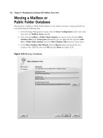
An SCC is basically a clustered mailbox server that consists of two or more servers (known as
nodes) that share the same storage (for databases and log fi les). The shared storage subsystem is typically
a SAN. In Figure 8.77 you can see what the architecture behind a typical SCC scenario looks like.
Queues DatabaseLogs
Shared Storage Subsystem
(Storage Area Network)
Private Network
(Heartbeat Network)
Mailbox Server
(Active Node)
Mailbox Server
(Passive Node)
Figure 8.77 A Basic Single Copy Cluster Scenario
NOTE
We know we mentioned it in the beginning of this chapter, but because it’s important
that you understand this concept, we repeat: Exchange Server 2007 no longer supports
active/active clusters. Only active/passive clusters are supported in Exchange 2007.
High Availability for Exchange 2007 Mailbox Servers • Chapter 8 553
The primary benefi t of an SCC is that it provides high availability of server resources because
one node takes over should the active node be taken offl ine or fail for some reason. In addition, you
can apply hotfi xes, service packs, and the like to the nodes without having any downtime of your
mission-critical mailbox servers. However, bear in mind that an SCC is susceptible to failure of the
shared storage subsystem. This means that no matter how many nodes are part of your cluster, you’ll
always have a single point of failure when you’re using SCC opposite a CCR-based cluster, which,
as we demonstrated, provides storage group failover via the new log fi le shipping and replay
functionality.
Since most of you don’t have the necessary hardware for a cluster, before you actually decide to
deploy one in your environment, we thought it would be a clever idea to show you how to install an
SCC in a Virtual Server 2005 R2 environment. Pretty much all the steps in this section can be used
to install the SCC on real hardware, too.
SOME INDEPENDENT ADVICE
Some of you might wonder whether standby blusters are supported in Exchange 2007,
just as they were in Exchange 2003. A standby cluster is a Windows cluster that
matches a production Exchange cluster in terms of hardware and software
confi guration, including Windows and Exchange versions and any updates or
hotfi xes that have been applied. In addition, a standby cluster has the Exchange
program fi les installed but has not yet been confi gured with any Exchange Virtual
Servers (EVS). Lastly, a standby cluster can only be used when all Exchange Virtual
Servers on the production cluster are offl ine.
So, is a standby cluster supported in Exchange 2007? The answer is no, but then it’s
really not that useful anymore, since Exchange 2007 gives us the ability to recover an
Exchange 2007 cluster using the new Exsetup /RecoverCMS switch (which is similar to
the /DisasterRecovery switch we know from previous versions of Exchange). Even better,
the /RecoverCMS switch can be used to recover both Exchange 2007 CCR and SCC-based
cluster setups. We’ll take a closer look at the /RecoverCMS switch in Chapter 10.
Prerequisites
To follow the steps throughout this section, you need the following:
■
One physical machine running Virtual Server 2005 R2. Since this product is free to
download from the Microsoft Web site, getting it shouldn’t be a problem. You can download
Virtual Server 2005 R2 from the following link: www.microsoft.com/windowsserversystem/
virtualserver/software/default.msp.
■
A Windows 2003 Active Directory forest with at least one domain controller (raised to 2000
or 2003 forest functional level).
■
At least one existing Exchange 2007 Hub Transport/Client Access server already installed in
the aforementioned forest.
554 Chapter 8 • High Availability for Exchange 2007 Mailbox Servers
■
Two virtual guests running Windows 2003 R2 or Windows 2003 SP1 Enterprise Edition
with at least 512MB RAM and two virtual NICs each—one for the Public network and
one for the Private network (the heartbeat network). This means that you need to create an
additional virtual network on the virtual host server; None (Guest Only) is suffi cient for
this network.
NOTE
To install a Exchange 2007 Single Copy Cluster, you also need to install the cluster
hotfi x mentioned in MS KB article 898790, which at the time of this writing can be
requested by contacting Microsoft Product Support Services. Microsoft is working on
making it public.
Confi guring the Network Settings for
each Network Interface
In this example, we’ll create an SCC consisting of two active/passive clusters that will be part of the
same Exchange organization as the CCR-based cluster we discussed previously in this chapter. This
means that you will need to install two NICs in each node (which we recommend you call public and
private so that you can see what belongs to which network) and then confi gure the private and public
interfaces for evach of the two nodes identically to the network interfaces we confi gured on the two
nodes in the CCR-based cluster setup. The only difference would be the IP addresses, since using the
same ones would result in IP confl icts, but everything from the binding order, WINS, DNS, and so on
should be the same for each interface. So instead of going through all the steps again, refer back to
the “Confi guring the Network Interfaces for Each Node” subsection of the “Managing a Cluster
Continuous Replication-Based Cluster Setup” section of this chapter.
Creating the Shared Cluster Disks
As those of you with cluster experience are aware, a Windows cluster requires a quorum cluster disk.
This quorum disk is used to store cluster confi guration database checkpoints and log fi les that help
manage the cluster as well as maintain consistency. Since we’re dealing with a virtual environment,
we need to create this disk in the Virtual Server 2005 R2 Web console. This is done by following
these steps:
1. Open the Virtual Server Manager, then click Create | Fixed Size Virtual Hard Disk
under Virtual Disks, as shown in Figure 8.78.
High Availability for Exchange 2007 Mailbox Servers • Chapter 8 555
Figure 8.78 Creating a Fixed-Size Virtual Hard Disk
2. Place the virtual hard disk fi le (.VHD) in the folder containing your two virtual Windows
2003 Servers, then set the size to 500MB (or less if you’re low on disk space). Then click
Create (see Figure 8.79).
Figure 8.79 Specifying the Virtual Hard Disk Filename and Size
556 Chapter 8 • High Availability for Exchange 2007 Mailbox Servers
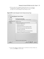
3. We now need to add the virtual quorum disk to each of the two virtual Windows 2003
Servers. Let’s add it to EDFS09 fi rst. We do this by clicking Master Status | EDFS09 |
Edit Confi guration. Since this disk needs to be shared between the nodes, we need to
click SCSI Adapters, then Add SCSI Adapter (see Figure 8.80). Under the new SCSI
adapter, check Share SCSI Bus for Clustering, then set the SCSI adapter ID to 6
(or whatever SCSI adapter ID is unused in your environment). Click OK.
Figure 8.80 Adding an Additional Shared SCSI Adapter
4. We now need to make the new disk visible on each node, so click Hard disks | Add disk,
then select SCSI 1 ID 0 in the Attachment drop-down menu. Finally, specify the path
to the virtual Quorum disk, which in this example is E:\E2K7SCC\Shared Disks\
Quorum.vhd, as shown in Figure 8.81. Click OK.