Electric Circuits, 9th Edition P2 ppt
Bạn đang xem bản rút gọn của tài liệu. Xem và tải ngay bản đầy đủ của tài liệu tại đây (349.32 KB, 10 trang )
Contents
List of Examples xiii
Preface xvii
Chapter 1 Circuit Variables 2
Practical Perspective: Balancing
Power
1.1 Electrical Engineering: An Overview 4
1.2 The International System of Units 8
1.3 Circuit Analysis: An Overview 10
1.4 Voltage and Current 11
1.5 The Ideal Basic Circuit Element 12
1.6 Power and Energy 14
Practical Perspective: Balancing
Power
Summary 18
Problems 19
17
Chapter 2 Circuit Elements 24
Practical Perspective: Electrical Safety 25
2.1 Voltage and Current Sources 26
2.2 Electrical Resistance (Ohm's Law) 30
2.3 Construction of a Circuit Model 34
2.4 Kirchhoff's Laws 37
2.5 Analysis of a Circuit Containing Dependent
Sources 42
Practical Perspective: Electrical Safety 46
Summary 47
Problems 48
Chapter 3 Simple Resistive Circuits 56
Practical Perspective: A Rear Window
Defroster 57
3.1 Resistors in Series 58
3.2 Resistors in Parallel 59
3.3 The Voltage-Divider and Current-Divider
Circuits 61
3.4 Voltage Division and Current Division 64
3.5 Measuring Voltage and Current 66
3.6 Measuring Resistance—The Wheatstone
Bridge 69
3.7 Delta-to-Wye (Pi-to-Tee) Equivalent
Circuits 71
Practical Perspective: A Rear Window
Defroster 73
Summary 76
Problems 77
Chapter 4 Techniques of Circuit
Analysis 88
Practical Perspective: Circuits with Realistic
Resistors 89
4.1 Terminology 90
4.2 Introduction to the Node-Voltage Method
4.3 The Node-Voltage Method and Dependent
Sources 95
4.4 The Node-Voltage Method: Some Special
Cases 96
4.5 Introduction to the Mesh-Current Method
4.6 The Mesh-Current Method and Dependent
Sources 102
4.7 The Mesh-Current Method: Some Special
Cases 103
4.8 The Node-Voltage Method Versus the
Mesh-Current Method 106
4.9 Source Transformations 109
4.10 Thevenin and Norton Equivalents 113
4.11 More on Deriving a Thevenin Equivalent
4.12 Maximum Power Transfer 120
4.13 Superposition 122
Practical Perspective: Circuits with Realistic
Resistors 125
Summary 129
Problems 130
Chapter 5 The Operational
Amplifier 144
Practical Perspective: Strain
Gages
145
5.1 Operational Amplifier Terminals 146
5.2 Terminal Voltages and Currents 146
5.3 The Inverting-Amplifier Circuit 150
5.4 The Summing-Amplifier Circuit 152
5.5 The Noninverting-Amplifier Circuit 153
5.6 The Difference-Amplifier Circuit 155
5.7 A More Realistic Model for the Operational
Amplifier 159
Practical Perspective: Strain
Gages
162
Summary 164
Problems 165
93
99
117
ix
x Contents
Chapter 6 Inductance, Capacitance, and
Mutual Inductance 174
Practical Perspective: Proximity Switches 175
6.1 The Inductor 176
6.2 The Capacitor 182
6.3 Series-Parallel Combinations of Inductance
and Capacitance 187
6.4 Mutual Inductance 189
6.5 A Closer Look at Mutual Inductance 193
Practical Perspective: Proximity Switches 200
Summary 203
Problems 204
Chapter 7 Response of First-Order
RL
and
RC
Circuits 212
Practical Perspective: A Flashing Light
Circuit 213
7.1 The Natural Response of an
RL
Circuit 214
7.2 The Natural Response of an
RC
Circuit 220
7.3 The Step Response of
RL
and
RC
Circuits 224
7.4 A General Solution for Step and Natural
Responses 231
7.5 Sequential Switching 236
7.6 Unbounded Response 240
7.7 The Integrating Amplifier 241
Practical Perspective: A Flashing Light
Circuit 245
Summary 246
Problems 247
Chapter 8 Natural and Step Responses
of
RLC
Circuits 264
Practical Perspective: An Ignition Circuit 265
8.1 Introduction to the Natural Response of a
Parallel
RLC
Circuit 266
8.2 The Forms of the Natural Response of a
Parallel
RLC
Circuit 270
8.3 The Step Response of a Parallel
RLC
Circuit 280
8.4 The Natural and Step Response of a Series
RLC
Circuit 285
8.5 A Circuit with Two Integrating Amplifiers 289
Practical Perspective: An Ignition Circuit 294
Summary 297
Problems 298
Chapter 9 Sinusoidal Steady-State
Analysis 306
Practical Perspective: A Household Distribution
Circuit 307
9.1 The Sinusoidal Source 308
9.2 The Sinusoidal Response 311
9.3 The Phasor 312
9.4 The Passive Circuit Elements in the Frequency
Domain 317
9.5 Kirchhoff s Laws in the Frequency
Domain 321
9.6 Series, Parallel, and Delta-to-Wye
Simplifications 322
9.7 Source Transformations and Thevenin-Norton
Equivalent Circuits 329
9.8 The Node-Voltage Method 332
9.9 The Mesh-Current Method 333
9.10 The Transformer 334
9.11 The Ideal Transformer 338
9.12 Phasor Diagrams 344
Practical Perspective: A Household Distribution
Circuit 346
Summary 347
Problems 348
Chapter 10 Sinusoidal Steady-State
Power Calculations 360
Practical Perspective: Heating Appliances 361
10.1 Instantaneous Power 362
10.2 Average and Reactive Power 363
10.3 The rms Value and Power Calculations 368
10.4 Complex Power 370
10.5 Power Calculations 371
10.6 Maximum Power Transfer 378
Practical Perspective: Heating Appliances 384
Summary 386
Problems 387
Chapter 11 Balanced Three-Phase
Circuits 398
Practical Perspective: Transmission and
Distribution of Electric Power 399
11.1 Balanced Three-Phase Voltages 400
11.2 Three-Phase Voltage Sources 401
11.3 Analysis of the Wye-Wye Circuit 402
11.4 Analysis of the Wye-Delta Circuit 407
11.5 Power Calculations in Balanced Three-Phase
Circuits 410
11.6 Measuring Average Power in Three-Phase
Circuits 415
Practical Perspective: Transmission and
Distribution of Electric Power 418
Summary 419
Problems 420
Contents xi
Chapter 12 Introduction to the Laplace
Transform 428
Practical
Perspective:
Transient Effects
429
12.1 Definition of the Laplace Transform 430
12.2 The Step Function 431
12.3 The Impulse Function 433
12.4 Functional Transforms 436
12.5 Operational Transforms 437
12.6 Applying the Laplace Transform 442
12.7 Inverse Transforms 444
12.8 Poles and Zeros of
F(s)
454
12.9 Initial- and Final-Value Theorems 455
Practical
Perspective:
Transient Effects
458
Summary 459
Problems 460
Chapter 13 The Laplace Transform in
Circuit Analysis 466
Practical
Perspective:
Surge Suppressors
467
13.1 Circuit Elements in the s Domain 468
13.2 Circuit Analysis in the s Domain 470
13.3 Applications 472
13.4 The Transfer Function 484
13.5 The Transfer Function in Partial Fraction
Expansions 486
13.6 The Transfer Function and the Convolution
Integral 489
13.7 The Transfer Function and the Steady-State
Sinusoidal Response 495
13.8 The Impulse Function in Circuit Analysis 498
Practical
Perspective:
Surge Suppressors
505
Summary 506
Problems 507
Chapter 14 Introduction to Frequency
Selective Circuits 522
Practical
Perspective:
Pushbutton Telephone
Circuits 523
14.1 Some Preliminaries 524
14.2 Low-Pass Filters 526
14.3 High-Pass Filters 532
14.4 Bandpass Filters 536
14.5 Bandreject Filters 545
Practical
Perspective:
Pushbutton Telephone
Circuits 550
Summary 550
Problems 551
Chapter 15 Active Filter Circuits 558
Practical
Perspective:
Bass Volume
Control 559
15.1 First-Order Low-Pass and High-Pass
Filters 560
15.2 Scaling 564
15.3 Op Amp Bandpass and Bandreject Filters 566
15.4 Higher Order Op Amp Filters 573
15.5 Narrowband Bandpass and Bandreject
Filters 586
Practical
Perspective:
Bass Volume
Control 591
Summary 594
Problems 595
Chapter 16 Fourier Series 604
Practical
Perspective:
Active High-Q Filters
605
16.1 Fourier Series Analysis: An Overview 607
16.2 The Fourier Coefficients 608
16.3 The Effect of Symmetry on the Fourier
Coefficients 611
16.4 An Alternative Trigonometric Form of the
Fourier Series 617
16.5 An Application 619
16.6 Average-Power Calculations with Periodic
Functions 623
16.7 The rms Value of a Periodic Function 626
16.8 The Exponential Form of the Fourier
Series 627
16.9 Amplitude and Phase Spectra 630
Practical
Perspective:
Active High-Q Filters
632
Summary 634
Problems 635
Chapter 17 The Fourier Transform 644
Practical
Perspective:
Filtering Digital
Signals 645
17.1 The Derivation of the Fourier Transform 646
17.2 The Convergence of the Fourier Integral 648
17.3 Using Laplace Transforms to Find Fourier
Transforms 650
17 A Fourier Transforms in the Limit 653
17.5 Some Mathematical Properties 655
17.6 Operational Transforms 657
17.7 Circuit Applications 661
17.8 Parseval's Theorem 664
Practical
Perspective:
Filtering Digital
Signals 671
Summary 672
Problems 672
xii Contents
Chapter 18 Two-Port Circuits 678
Practical Perspective: Characterizing an
Unknown Circuit 679
18.1 The Terminal Equations 680
18.2 The Two-Port Parameters 681
18.3 Analysis of the Terminated Two-Port
Circuit 689
18.4 Interconnected Two-Port Circuits 694
Practical Perspective: Characterizing an
Unknown Circuit 697
Summary 698
Problems 698
Appendix A The Solution of Linear
Simultaneous Equations 705
A.l Preliminary Steps 705
A.2 Cramer's Method 706
A.3 The Characteristic Determinant 706
A.4 The Numerator Determinant 706
A.5 The Evaluation of a Determinant 707
A.6 Matrices 709
A. 7 Matrix Algebra 710
A.8 Identity, Adjoint, and Inverse Matrices 714
A.9 Partitioned Matrices 717
A.10 Applications 720
Appendix B Complex Numbers 725
B.l Notation 725
B.2 The Graphical Representation of a Complex
Number 726
B.3 Arithmetic Operations 727
B.4 Useful Identities 728
B.5 The Integer Power of a Complex Number 729
B.6 The Roots of a Complex Number 729
Appendix
C
More on Magnetically
Coupled Coils and Ideal
Transformers 731
C.l Equivalent Circuits for Magnetically Coupled
Coils 731
C.2 The Need for Ideal Transformers in the
Equivalent Circuits 735
Appendix D The Decibel 739
Appendix
E
Bode Diagrams 741
E.l Real, First-Order Poles and Zeros 741
E.2 Straight-Line Amplitude Plots 742
E.3 More Accurate Amplitude Plots 746
E.4 Straight-Line Phase Angle Plots 747
E.5 Bode Diagrams: Complex Poles and Zeros 749
E.6 Amplitude Plots 751
E.7 Correcting Straight-Line Amplitude Plots 752
E.8 Phase Angle Plots 755
Appendix F An Abbreviated Table of
Trigonometric Identities 759
Appendix
G
An Abbreviated Table of
Integrals
761
Appendix H Common Standard
Component Values 763
Answers to Selected Problems 765
Index 781
in iw
am
A
List of Examples
Chapter 1
1.1 Using SI Units and Prefixes for Powers of 10 10
1.2 Relating Current and Charge 14
1.3 Relating Voltage, Current, Power, and Energy 16
Chapter 2
2.1 Testing Interconnections of Ideal Sources 28
2.2 Testing Interconnections of Ideal Independent
and Dependent Sources 29
2.3 Calculating Voltage, Current, and Power for a
Simple Resistive Circuit 33
2.4 Constructing a Circuit Model of a Flashlight 34
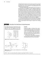
2.5 Constructing a Circuit Model Based on Terminal
Measurements 36
2.6 Using Kirchhoff's Current Law 39
2.7 Using Kirchhoff's Voltage Law 40
2.8 Applying Ohm's Law and Kirchhoff's Laws to
Find an Unknown Current 40
2.9 Constructing a Circuit Model Based on Terminal
Measurements 41
2.10 Applying Ohm's Law and Kirchhoff's Laws to
Find an Unknown Voltage 44
2.11 Applying Ohm's Law and Kirchhoff's Law in an
Amplifier Circuit 45
Chapter 3
3.1 Applying Series-Parallel Simplification 60
3.2 Analyzing the Voltage-Divider Circuit 62
3.3 Analyzing a Current-Divider Circuit 63
3.4 Using Voltage Division and Current Division to
Solve a Circuit 66
3.5 Using a d'Arsonval Ammeter 68
3.6 Using a d'Arsonval Voltmeter 68
3.7 Applying a Delta-to-Wye Transform 72
Chapter 4
4.1 Identifying Node, Branch, Mesh and Loop in a
Circuit 90
4.2 Using the Node-Voltage Method 94
4.3 Using the Node-Voltage Method with
Dependent Sources 95
4.4 Using the Mesh-Current Method 101
4.5 Using the Mesh-Current Method with
Dependent Sources 102
4.6 Understanding the Node-Voltage Method
Versus Mesh-Current Method 107
4.7 Comparing the Node-Voltage and Mesh-Current
Methods 108
4.8 Using Source Transformations to Solve
a Circuit 110
4.9 Using Special Source Transformation
Techniques 112
4.10 Finding the Thevenin Equivalent of a Circuit
with a Dependent Source 116
4.11 Finding the Thevenin Equivalent Using a Test
Source 118
4.12 Calculating the Condition for Maximum Power
Transfer 121
4.13 Using Superposition to Solve a Circuit 124
Chapter 5
5.1 Analyzing an Op Amp Circuit 149
5.2 Designing an Inverting Amplifier 151
5.3 Designing a Noninverting Amplifier 154
5.4 Designing a Difference Amplifier 155
Chapter 6
6.1 Determining the Voltage, Given the Current,
at the Terminals of an Inductor 177
6.2 Determining the Current, Given the Voltage,
at the Terminals of an Inductor 178
6.3 Determining the Current, Voltage, Power,
and Energy for an Inductor 180
6.4 Determining Current, Voltage, Power, and
Energy for a Capacitor 184
6.5 Finding v, p, and w Induced by a Triangular
Current Pulse for a Capacitor 185
6.6 Finding Mesh-Current Equations for a Circuit
with Magnetically Coupled Coils 192
Chapter 7
7.1 Determining the Natural Response of an
RL Circuit 218
7.2 Determining the Natural Response of an
RL
Circuit with Parallel Inductors 219
7.3 Determining the Natural Response of an
RC
Circuit 222
7.4 Determining the Natural Response of an
RC
Circuit with Series Capacitors 223
xiii
xiv
List
of
Examples
7.5 Determining the Step Response of an
RL
Circuit 227
7.6 Determining the Step Response of an
RC
Circuit 230
7.7 Using the General Solution Method to Find an
RC
Circuit's Step Response 233
7.8 Using the General Solution Method with Zero
Initial Conditions 234
7.9 Using the General Solution Method to Find an
RL Circuit's Step Response 234
7.10 Determining the Step Response of a Circuit
with Magnetically Coupled Coils 235
7.11 Analyzing an RL Circuit that has Sequential
Switching 237
7.12 Analyzing an
RC
Circuit that has Sequential
Switching 239
7.13 Finding the Unbounded Response in an
RC
Circuit 241
7.14 Analyzing an Integrating Amplifier 243
7.15 Analyzing an Integrating Amplifier that has
Sequential Switching 243
Chapter 8
8.1 Finding the Roots of the Characteristic
Equation of a Parallel
RLC
Circuit 269
8.2 Finding the Overdamped Natural Response of a
Parallel
RLC
Circuit 272
8.3 Calculating Branch Currents in the Natural
Response of a Parallel
RLC
Circuit 273
8.4 Finding the Underdamped Natural Response of
a Parallel
RLC
Circuit 275
8.5 Finding the Critically Damped Natural
Response of a Parallel
RLC
Circuit 278
8.6 Finding the Overdamped Step Response of a
Parallel
RLC
Circuit 282
8.7 Finding the Underdamped Step Response of a
Parallel
RLC
Circuit 283
8.8 Finding the Critically Damped Step Response
of a Parallel
RLC
Circuit 283
8.9 Comparing the Three-Step Response Forms 284
8.10 Finding Step Response of a Parallel
RLC
Circuit
with Initial Stored Energy 284
8.11 Finding the Underdamped Natural Response of
a Series
RLC
Circuit 287
8.12 Finding the Underdamped Step Response of a
Series
RLC
Circuit 288
8.13 Analyzing Two Cascaded Integrating
Amplifiers 290
8.14 Analyzing Two Cascaded Integrating Amplifiers
with Feedback Resistors 293
Chapter 9
9.1 Finding the Characteristics of a Sinusoidal
Current 309
9.2 Finding the Characteristics of a Sinusoidal
Voltage 310
9.3 Translating a Sine Expression to a Cosine
Expression 310
9.4 Calculating the rms Value of a Triangular
Waveform 310
9.5 Adding Cosines Using Phasors 316
9.6 Combining Impedances in Series 323
9.7 Combining Impedances in Series and in
Parallel 325
9.8 Using a Delta-to-Wye Transform in the
Frequency Domain 327
9.9 Performing Source Transformations in the
Frequency Domain 329
9.10 Finding a Thevenin Equivalent in the
Frequency Domain 330
9.11 Using the Node-Voltage Method in the
Frequency Domain 332
9.12 Using the Mesh-Current Method in the
Frequency Domain 333
9.13 Analyzing a Linear Transformer in the
Frequency Domain 337
9.14 Analyzing an Ideal Transformer Circuit in the
Frequency Domain 342
9.15 Using Phasor Diagrams to Analyze a
Circuit 344
9.16 Using Phasor Diagrams to Analyze Capacitive
Loading Effects 345
Chapter 10
10.1 Calculating Average and Reactive Power 366
10.2 Making Power Calculations Involving
Household Appliances 367
10.3 Determining Average Power Delivered to a
Resistor by a Sinusoidal Voltage 369
10.4 Calculating Complex Power 371
10.5 Calculating Average and Reactive Power 374
10.6 Calculating Power in Parallel Loads 375
10.7 Balancing Power Delivered with Power
Absorbed in an ac Circuit 376
10.8 Determining Maximum Power Transfer without
Load Restrictions 380
10.9 Determining Maximum Power Transfer with
Load Impedance Restriction 381
10.10 Finding Maximum Power Transfer with
Impedance Angle Restrictions 382
10.11 Finding Maximum Power Transfer in a Circuit
with an Ideal Transformer 383
List
of
Examples
XV
Chapter 11
11.1 Analyzing a Wye-Wye Circuit 405
11.2 Analyzing a Wye-Delta Circuit 408
11.3 Calculating Power in a Three-Phase Wye-Wye
Circuit 413
11.4 Calculating Power in a Three-Phase Wye-Delta
Circuit 413
11.5 Calculating Three-Phase Power with
an Unspecified Load 414
11.6 Computing Wattmeter Readings in Three-Phase
Circuits 417
Chapter 12
12.1 Using Step Functions to Represent a Function
of Finite Duration 432
Chapter 13
13.1 Deriving the Transfer Function of a Circuit 485
13.2 Analyzing the Transfer Function
of a Circuit 487
13.3 Using the Convolution Integral to Find
an Output Signal 493
13.4 Using the Transfer Function to Find
the Steady-State Sinusoidal Response 497
Chapter 14
14.1 Designing a Low-Pass Filter 529
14.2 Designing a Series
RC
Low-Pass Filter 530
14.3 Designing a Series
RL
High-Pass Filter 534
14.4 Loading the Series
RL
High-Pass Filter 534
14.5 Designing a Bandpass Filter 540
14.6 Designing a Parallel
RLC
Bandpass Filter 541
14.7 Determining Effect of a Nonideal Voltage
Source on a
RLC
Bandpass Filter 542
14.8 Designing a Series
RLC
Bandreject Filter 548
15.9 Designing a Fourth-Order Low-Pass
Butterworth Filter 581
15.10 Determining the Order of a Butterworth
Filter 584
15.11 An Alternate Approach to Determining
the Order of a Butterworth Filter 584
15.12 Designing a High-Q Bandpass Filter 588
15.13 Designing a High-Q Bandreject Filter 590
Chapter 16
16.1 Finding the Fourier Series of a Triangular
Waveform with No Symmetry 609
16.2 Finding the Fourier Series of an Odd Function
with Symmetry 616
16.3 Calculating Forms of the Trigonometric Fourier
Series for Periodic Voltage 618
16.4 Calculating Average Power for a Circuit
with a Periodic Voltage Source 625
16.5 Estimating the rms Value of a Periodic
Function 627
16.6 Finding the Exponential Form of the Fourier
Series 629
Chapter 17
17.1 Using the Fourier Transform to Find
the Transient Response 662
17.2 Using the Fourier Transform to Find the
Sinusoidal Steady-State Response 663
17.3 Applying Parseval's Theorem 666
17.4 Applying Parseval's Theorem to an Ideal
Bandpass Filter 667
17.5 Applying Parseval's Theorem to a Low-Pass
Filter 668
Chapter 18
18.1 Finding the z Parameters of a Two-Port
Circuit 681
18.2 Finding the a Parameters from
Measurements 683
18.3 Finding h Parameters from Measurements
and Table 18.1 686
18.4 Analyzing a Terminated Two-Port Circuit 692
18.5 Analyzing Cascaded Two-Port Circuits 696
Chapter 15
15.1 Designing a Low-Pass Op Amp Filter 561
15.2 Designing a High-Pass Op Amp Filter 563
15.3 Scaling a Series
RLC
Circuit 565
15.4 Scaling a Prototype Low-Pass Op Amp
Filter 565
15.5 Designing a Broadband Bandpass Op Amp
Filter 569
15.6 Designing a Broadband Bandreject Op Amp
Filter 572
15.7 Designing a Fourth-Order Low-Pass Op Amp
Filter 576
15.8
Calculating Butterworth Transfer
Functions 579
The ninth edition of Electric Circuits represents a planned revision designed
to incrementally improve this introductory circuits text used by more than
700,000 students worldwide during the past 28 years. While the book has
evolved over the years to meet the changing learning styles of students, the
fundamental goals of the text remain unchanged. These goals are:
• To build an understanding of concepts and ideas explicitly in terms of
previous learning. Students are constantly challenged by the need to
layer new concepts on top of previous concepts they may still be
struggling to master. This text provides an important focus on helping
students understand how new concepts are related to and rely upon
concepts previously presented.
• To emphasize the relationship between conceptual understanding
and problem-solving approaches. Developing problem-solving skills
continues to be the central challenge in a first-year circuits course. In
this text we include numerous Examples that present problem-
solving techniques followed by Assessment Problems that enable
students to test their mastery of the material and techniques intro-
duced. The problem-solving process we illustrate is based on con-
cepts rather than the use of rote procedures. This encourages
students to think about a problem before attempting to solve it.
• To provide students with a strong foundation of engineering prac-
tices.
There are limited opportunities in a first-year circuit analysis
course to introduce students to realistic engineering experiences. We
continue to take advantage of the opportunities that do exist by
including problems and examples that use realistic component values
and represent realizable circuits. We include many problems related
to the Practical Perspective problems that begin each chapter. We
also include problems intended to stimulate the students' interest in
engineering, where the problems require the type of insight typical of
a practicing engineer.
WHY THIS EDITION?
The ninth edition revision of Electric Circuits began with a thorough
review of the text by instructors who currently use Electric Circuits and
those who use other
texts.
This review provided a clear picture of what mat-
ters most to instructors and their students and led to the following changes:
• Problem solving is fundamental to the study of circuit analysis.
Having a wealth of new problems to assign and work is a key to suc-
cess in any circuits course. Therefore, existing end-of-chapter prob-
lems were revised, and new end-of-chapter problems were added.
The result is a text with approximately 75% new or revised problems
compared to the previous edition.
• Both students and instructors want to know how the generalized
techniques presented in a first-year circuit analysis course relate to
problems faced by practicing engineers. The Practical Perspective
problems provide this connection between circuit analysis and the
real world. We have expanded the use of the Practical Perspectives so
xvn