Electric Circuits, 9th Edition P3 pptx
Bạn đang xem bản rút gọn của tài liệu. Xem và tải ngay bản đầy đủ của tài liệu tại đây (1.29 MB, 10 trang )
that they now appear at the start of every chapter. Each Practical
Perspective problem is solved, at least in part, at the end of the chap-
ter, and additional end-of-chapter problems can be assigned to allow
students to explore the Practical Perspective topic further.
• Examples embedded in the text that illustrate the application of con-
cepts just presented are an important tool to improve student under-
standing. The ninth edition adds new examples and now all chapters
except Chapter 12 have a minimum of four examples. Chapter 12,
which presents an introduction to Laplace transform techniques, is
comprised of a collection of examples, but does not follow the format
of concept-example employed by the other chapters.
• Previous editions of Electric Circuits contained many end-of-chapter
problems with circuits comprised of components with standard val-
ues.
These circuits could actually be constructed and tested in a labo-
ratory. New to the ninth edition is Appendix H, which lists standard
values for resistors, inductors, and capacitors. Also new are
end-of-
chapter problems for most chapters that ask students to use compo-
nents from Appendix H to construct circuits that meet particular
requirements. The use of standard components is another effort to tie
circuit analysis concepts to real-world circuits.
• Previous editions of Electric Circuits have been published with an
optional separate paperback manual presenting an introduction to
PSpice and its use in simulating circuits a student encounters in their
study of linear circuits. With the ninth edition, students and instruc-
tors can choose from two circuit-simulation manuals—PSpice, or
Multisim. Each manual presents the simulation material in the same
order as the material is presented in the text. These manuals continue
to include examples of circuits to be simulated that are drawn
directly from the text. The text continues to indicate end-of-chapter
problems that are good candidates for simulation using either PSpice
or Multisim.
• Students who could benefit from additional examples and practice
problems can use the Student Workbook. This workbook has exam-
ples and problems covering the following material: balancing power,
simple resistive circuits, node voltage method, mesh current method,
Thevenin and Norton equivalents, op amp circuits, first-order cir-
cuits,
second-order circuits, AC steady-state analysis, and Laplace
transform circuit analysis.
• Instructors and students benefit greatly from thoughtful methods of
assessing student learning. The ninth edition makes PowerPoint pre-
sentations available to instructors that include embedded assessment
questions. During a lecture, the instructor can present material using
PowerPoint, pose a question to the students concerning that material,
and allow students to respond to the question. Using a Classroom
Response System, results from student responses are immediately
available to the instructor, providing real-time information about the
students' comprehension of the material. This immediate feedback
allows the instructor go back and revisit material the students did not
comprehend, or to continue presenting new material if comprehen-
sion is satisfactory.
• Every new copy of the book now comes with access to Video
Solutions and a Pearson etext. Video solutions are complete, step-by-
step solution walkthroughs of representative homework problems.
The Pearson etext is a complete on-line version of the book that
includes highlighting, note-taking and search capabilities.
HALLMARK FEATURES
Chapter Problems
Users of
Electric Circuits
have consistently rated the Chapter Problems
as one of the book's most attractive features. In the ninth edition, there
are over 1300 problems with approximately
75%
that are new or revised
from the previous edition. Problems are organized at the end of each
chapter by section.
Practical Perspectives
The ninth edition continues the use of Practical Perspectives introduced
with the chapter openers. They offer examples of real-world circuits, taken
from real-world
devices.
Every chapter begins with a brief description of a
practical application of the material that follows. Once the chapter mate-
rial is presented, the chapter concludes with a quantitative analysis of the
Practical Perspective application. A group of end-of-chapter problems
directly relates to the Practical Perspective application. Solving some of
these problems enables you to understand how to apply the chapter con-
tents to the solution of a real-world problem.
Assessment Problems
Each chapter begins with a set of chapter objectives. At key points in the
chapter, you are asked to stop and assess your mastery of a particular
objective by solving one or more assessment
problems.
The answers to all
of the assessment problems are given at the conclusion of each problem, so
you can check your work. If you are able to solve the assessment problems
for a given objective, you have mastered that objective. If you need more
practice, several end-of-chapter problems that relate to the objective are
suggested at the conclusion of the assessment problems.
Examples
Every chapter includes many examples that illustrate the concepts
presented in the text in the form of a numeric example. There are
nearly 150 examples in this text. The examples are intended to illus-
trate the application of a particular concept, and also to encourage
good problem-solving skills.
Fundamental Equations and Concepts
Throughout the text, you will see fundamental equations and concepts
set apart from the main text. This is done to help you focus on some of the
key principles in electric circuits and to help you navigate through the
important topics.
Integration of Computer Tools
Computer tools can assist students in the learning process by providing a
visual representation of a circuit's behavior, validating a calculated solu-
tion, reducing the computational burden of more complex circuits, and
iterating toward a desired solution using parameter variation. This compu-
tational support is often invaluable in the design process. The ninth edition
includes the support of PSpice® and Multisim®, both popular computer
tools for circuit simulation and analysis. Chapter problems suited for
exploration with PSpice and Multisim are marked accordingly.
Design Emphasis
The ninth edition continues to support the emphasis on the design of cir-
cuits in many ways. First, many of the Practical Perspective discussions
focus on the design aspects of the circuits. The accompanying Chapter
Problems continue the discussion of the design issues in these practical
examples. Second, design-oriented Chapter Problems have been labeled
explicitly, enabling students and instructors to identify those problems
with a design focus. Third, the identification of problems suited to explo-
ration with PSpice or Multisim suggests design opportunities using these
software tools. Fourth, new problems have been added to most chapters
that focus on the use of realistic component values in achieving a desired
circuit design. Once such a problem has been analyzed, the student can
proceed to a laboratory to build and test the circuit, comparing the analy-
sis with the measured performance of the actual circuit.
Accuracy
All text and problems in the ninth edition have undergone our strict hall-
mark accuracy checking process, to ensure the most error-free book possible.
RESOURCES FOR STUDENTS
Companion Website. The Companion Website, located at www.
pearsonhighered.com/nilsson, includes opportunities for practice and
review including:
• Video Solutions - Complete, step-by-step solution walkthroughs of
representative homework problems for each chapter.
• Pearson etext - A complete on-line version of the book that includes
highlighting, note-taking and search capabilities.
• On-Line Study Guide - Chapter-by-Chapter notes that highlight key
concepts of electric circuits
An access code to the Companion Website is included with the purchase
of every new copy of Nilsson/Riedel, Electric Circuits 9e and can be
redeemed at www.pearsonhighered.com/nilsson. Access can also be pur-
chased directly from the site.
Student Study Pack. This resource teaches students techniques for solv-
ing problems presented in the text. Organized by concepts, this is a valu-
able problem-solving resource for all levels of students.
Introduction to Multisim and Introduction to PSpice Manuals—Updated
for the ninth edition, these manuals are excellent resources for those wish-
ing to integrate PSpice or Multisim into their classes.
RESOURCES FOR INSTRUCTORS
All instructor resources are available for download at www.pearsonhigh-
ered.com. If you are in need of a login and password for this site, please
contact your local Pearson representative.
Instructor Solutions Manual—Fully worked-out solutions to
end-of-
chapter problems
PowerPoint lecture images—All figures from the text are available in
PowerPoint for vour lecture needs.
Custom Solutions—New options for textbook customization are now
available for Electric Circuits, Ninth Edition. Please contact your local
Pearson representative for details.
PREREQUISITES
In writing the first 12 chapters of the text, we have assumed that the
reader has taken a course in elementary differential and integral calculus.
We have also assumed that the reader has had an introductory physics
course, at either the high school or university level, that introduces the
concepts of energy, power, electric charge, electric current, electric poten-
tial,
and electromagnetic fields. In writing the final six chapters, we have
assumed the student has had, or is enrolled in, an introductory course in
differential equations.
COURSE OPTIONS
The text has been designed for use in a one-semester, two-semester, or a
three-quarter sequence.
• Single-semester
course:
After covering Chapters 1-4 and Chapters 6-10
(omitting Sections 7.7 and 8.5) the instructor can choose from
Chapter 5 (operational amplifiers), Chapter 11 (three-phase circuits).
Chapters 13 and 14 (Laplace methods), and Chapter 18 (Two-Port
Circuits) to develop the desired emphasis.
• Two-semester sequence: Assuming three lectures per week, the first
nine chapters can be covered during the first semester, leaving
Chapters 10-18 for the second semester.
• Academic quarter schedule: The book can be subdivided into three
parts:
Chapters 1-6, Chapters 7-12, and Chapters 13-18.
The introduction to operational amplifier circuits in Chapter 5 can be
omitted without interfering with the reading of subsequent chapters. For
example, if Chapter 5 is omitted, the instructor can simply skip Section 7.7,
Section 8.5, Chapter 15, and those assessment problems and
end-of-
chapter problems in the chapters following Chapter 5 that pertain to oper-
ational amplifiers.
There are several appendixes at the end of the book to help readers
make effective use of their mathematical background. Appendix A reviews
Cramer's method of solving simultaneous linear equations and
simple matrix algebra; complex numbers are reviewed in Appendix B;
Appendix C contains additional material on magnetically coupled coils
and ideal transformers; Appendix D contains a brief discussion of the deci-
bel;
Appendix E is dedicated to Bode diagrams; Appendix F is devoted to
an abbreviated table of trigonometric identities that are useful in circuit
analysis; and an abbreviated table of useful integrals is given in Appendix G.
A new Appendix H provides tables of common standard component values
for resistors, inductors, and capacitors, to be used in solving many new
end-of-chapter problems. Selected Answers provides answers to selected
end-of-chapter problems.
ACKNOWLEDGMENTS
There were many hard-working people behind the scenes at our publisher
who deserve our thanks and gratitude for their efforts on behalf of the
ninth edition. At Pearson, we would like to thank Andrew Gilfillan,
Rose Kernan, Lisa McDowell, Kristine Carney, Tim Galligan, and
Scott Disanno for their continued support and a ton of really hard work.
Trie authors would also like to acknowledge the staff at GEX Publishing
Services for their dedication and hard work in typesetting this text. The
authors would also like to thank Kurt Norlin of Laurel Technical Services
for his help in accuracy checking the text and problems.
The many revisions of the text were guided by careful and thorough
reviews from professors. Our heartfelt thanks to:
Keith Holbert, Arizona State University
Sameer Sharma, Trine University
Selahattin Sayil, Lamar University
James Carstensen, Valencia Community College
Michael Polis, Oakland University
Alexander Balandin, University of California, Riverside
Guillermo Conde, University of Idaho
Paul Gordy, Tidewater Community College
Charles Giardina, California Polytechnic State University
Harold Underwood, Messiah College
Len Trombetta, University of Houston
Zahra Moussavi, University of Manitoba
Stephen Kahne, Embry-Riddle University
Jose Rios, Metropolitan State College of Denver
Bruce Dunne, Grand Valley State University
Ali Golbazi, University of New Haven
Pedda Sannuti, Rutgers University
John Post, Embry-Riddle Aeronautical University
Mohammad Hassan Modir Shanechi, Illinois Institute of Technology
A. John Boye, University of Nebraska
Ari Arapostathis, University of Texas
Brian Skromme, Arizona State University
Reza Hashemian, Northern Illinois University
Lan Xiang, Montgomery College
We are deeply indebted to the many instructors and students who
have offered positive feedback and suggestions for improvement. We are
delighted whenever we receive email from instructors and students who
use the book, even when they are pointing out an error we failed to catch
in the review process. We have been contacted by people who use our text
from all over the world, and even from someone who went to kinder-
garten with one of us! We use as many of your suggestions as possible to
continue to improve the content, the pedagogy, and the presentation in
this text. We are privileged to have the opportunity to impact the educa-
tional experience of the many thousands of future engineers who will turn
the pages of this text.
James
W.
Nilsson
Susan A. Riedel
ELECTRIC CIRCUITS
NINTH EDITION
ra
•U \
CHAPTER CONTENTS
1.1 Electrical Engineering: An Overview p. 4
1.2 The International System of Units p. 8
1.3 Circuit Analysis: An Overview p. 10
1.4 Voltage and Current p. 11
1.5 The Ideal Basic Circuit Element p. 12
1.6 Power and Energy p. 14
/"CHAPTER OBJECTIVES
1 Understand and
be
able
to
use
SI
units and
the
standard prefixes
for
powers
of 10.
2 Know and
be
able
to
use
the
definitions
of
voltage and current.
3 Know and
be
able
to
use
the
definitions
of
power and energy.
4
Be
able
to
use
the
passive sign convention
to
calculate
the
power
for
an ideal basic circuit
element given
its
voltage and current.
Circuit Variables
Electrical engineering
is an
exciting and challenging profession
for anyone
who has a
genuine interest
in, and
aptitude
for,
applied science
and
mathematics. Over
the
past century
and a
half,
electrical engineers have played
a
dominant role
in the
development
of
systems that have changed
the
way people live
and work. Satellite communication links, telephones, digital com-
puters, televisions, diagnostic
and
surgical medical equipment,
assembly-line robots,
and
electrical power tools
are
representa-
tive components
of
systems that define
a
modern technological
society.
As
an electrical engineer, you can participate in this ongo-
ing technological revolution
by
improving
and
refining these
existing systems
and
by discovering and developing new systems
to meet the needs
of
our ever-changing society.
As
you
embark
on the
study
of
circuit analysis, you need
to
gain
a
feel
for
where this study fits into
the
hierarchy
of
topics
that comprise an introduction to electrical engineering. Hence we
begin
by
presenting
an
overview
of
electrical engineering, some
ideas about
an
engineering point
of
view
as it
relates
to
circuit
analysis, and
a
review
of
the international system
of
units.
We then describe generally what circuit analysis
entails.
Next,
we introduce the concepts of voltage and current. We follow these
concepts with discussion
of an
ideal basic element
and the
need
for
a
polarity reference system.
We
conclude
the
chapter
by
describing how current and voltage relate to power and energy.
2
MM
M
Practical Perspective
Balancing Power
One of the most important skills you will develop is the
ability to check your answers for the circuits you design
and analyze using the tools developed in this text. A com-
mon method used to check for valid answers is to balance
the power in the circuit. The linear circuits we study have
no net power, so the sum of the power associated with each
circuit component must be zero. If the total power for
the circuit is zero, we say that the power balances, but if
the total power is not zero, we need to find the errors in
our calculation.
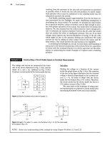
As an example, we will consider a very simple model for
the distribution of electricity to a typical home, as shown
below. (Note that a more realistic model will be investigated
in the Practical Perspective for Chapter 9.) The components
labeled a and b represent the electrical source to the home.
The components labeled c, d, and e represent the wires that
carry the electrical current from the source to the devices in
the home requiring electrical power. The components labeled
f, g, and h represent lamps, televisions, hair dryers, refriger-
ators,
and other devices that require power.
Once we have introduced the concepts of voltage, current,
power, and energy, we will examine this circuit model in detail,
and use a power balance to determine whether the results of
analyzing this circuit are correct.
;
t
\
c
)
d
f
g
h
Circuit Variables
Transmission
antenna
Microph
Telephone Telephone
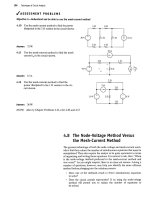
Figure
1.1 •
A telephone
system.
1.1 Electrical Engineering: An Overview
Electrical engineering is the profession concerned with systems that
produce, transmit, and measure electric signals. Electrical engineering
combines the physicist's models of natural phenomena with the mathe-
matician's tools for manipulating those models to produce systems that
meet practical needs. Electrical systems pervade our lives; they are found
in homes, schools, workplaces, and transportation vehicles everywhere.
We begin by presenting a few examples from each of the five major class-
ifications of electrical systems:
• communication systems
• computer systems
• control systems
• power systems
• signal-processing systems
Then we describe how electrical engineers analyze and design such systems.
Communication systems are electrical systems that generate, trans-
mit, and distribute information. Well-known examples include television
equipment, such as cameras, transmitters, receivers, and VCRs; radio tele-
scopes, used to explore the universe; satellite systems, which return images
of other planets and our own; radar systems, used to coordinate plane
flights; and telephone systems.
Figure 1.1 depicts the major components of a modern telephone sys-
tem. Starting at the left of the figure, inside a telephone, a microphone turns
sound waves into electric signals. These signals are carried to a switching
center where they are combined with the signals from tens, hundreds, or
thousands of other telephones. The combined signals leave the switching
center; their form depends on the distance they must travel. In our example,
they are sent through wires in underground coaxial cables to a microwave
transmission station. Here, the signals are transformed into microwave fre-
quencies and broadcast from a transmission antenna through air and space,
via a communications satellite, to a receiving antenna. The microwave
receiving station translates the microwave signals into a form suitable for
further transmission, perhaps as pulses of light to be sent through fiber-optic
cable. On arrival at the second switching center, the combined signals are
separated, and each is routed to the appropriate telephone, where an ear-
phone acts as a speaker to convert the received electric signals back into
sound waves. At each stage of the process, electric circuits operate on the
signals. Imagine the challenge involved in designing, building, and operating
each circuit in a way that guarantees that all of the hundreds of thousands of
simultaneous calls have high-quality connections.
Computer systems use electric signals to process information rang-
ing from word processing to mathematical computations. Systems range
in size and power from pocket calculators to personal computers to
supercomputers that perform such complex tasks as processing weather
data and modeling chemical interactions of complex organic molecules.
These systems include networks of microcircuits, or integrated circuits—
postage-stampsized assemblies of hundreds, thousands, or millions of
electrical components that often operate at speeds and power levels close
to fundamental physical limits, including the speed of light and the thermo-
dynamic laws.
Control systems use electric signals to regulate processes. Examples
include the control of temperatures, pressures, and flow rates in an oil
refinery; the fuel-air mixture in a fuel-injected automobile engine; mecha-
nisms such as the motors, doors, and lights in elevators; and the locks in the
1.1 Electrical Engineering:
An
Overview 5
Panama Canal. The autopilot and autolanding systems that help to fly and
land airplanes are also familiar control systems.
Power systems generate and distribute electric power. Electric power,
which is the foundation of our technology-based society, usually is gener-
ated in large quantities by nuclear, hydroelectric, and thermal (coal-, oil-,
or gas-fired) generators. Power is distributed by a grid of conductors that
crisscross the country. A major challenge in designing and operating such
a system is to provide sufficient redundancy and control so that failure of
any piece of equipment does not leave a city, state, or region completely
without power.
Signal-processing systems act on electric signals that represent infor-
mation. They transform the signals and the information contained in them
into a more suitable form. There are many different ways to process the
signals and their information. For example, image-processing systems
gather massive quantities of data from orbiting weather satellites, reduce
the amount of data to a manageable level, and transform the remaining
data into a video image for the evening news broadcast. A computerized
tomography (CT) scan is another example of an image-processing system.
It takes signals generated by a special X-ray machine and transforms them
into an image such as the one in Fig. 1.2. Although the original X-ray sig-
nals are of little use to a physician, once they are processed into a recog-
nizable image the information they contain can be used in the diagnosis of
disease and injury.
Considerable interaction takes place among the engineering disci-
plines involved in designing and operating these five classes of systems.
Thus communications engineers use digital computers to control the flow
of information. Computers contain control systems, and control systems
contain computers. Power systems require extensive communications sys-
tems to coordinate safely and reliably the operation of components, which
may be spread across a continent. A signal-processing system may involve
a communications link, a computer, and a control system.
A good example of the interaction among systems is a commercial
airplane, such as the one shown in Fig. 1.3. A sophisticated communica-
tions system enables the pilot and the air traffic controller to monitor the
plane's location, permitting the air traffic controller to design a safe flight
path for all of the nearby aircraft and enabling the pilot to keep the plane
on its designated path. On the newest commercial airplanes, an onboard
computer system is used for managing engine functions, implementing
the navigation and flight control systems, and generating video informa-
tion screens in the cockpit. A complex control system uses cockpit com-
mands to adjust the position and speed of the airplane, producing the
appropriate signals to the engines and the control surfaces (such as the
wing flaps, ailerons, and rudder) to ensure the plane remains safely air-
borne and on the desired flight path. The plane must have its own power
system to stay aloft and to provide and distribute the electric power
needed to keep the cabin lights on, make the coffee, and show the movie.
Signal-processing systems reduce the noise in air traffic communications
and transform information about the plane's location into the more
meaningful form of a video display in the cockpit. Engineering challenges
abound in the design of each of these systems and their integration into a
coherent whole. For example, these systems must operate in widely vary-
ing and unpredictable environmental conditions. Perhaps the most
important engineering challenge is to guarantee that sufficient redun-
dancy is incorporated in the designs to ensure that passengers arrive
safely and on time at their desired destinations.
Although electrical engineers may be interested primarily in one
area, they must also be knowledgeable in other areas that interact with
this area of interest. This interaction is part of what makes electrical
Figure 1.2 A
A CT
scan of
an
adult head.
Figure 1.3 A
An
airplane.