Electric Circuits, 9th Edition P6 doc
Bạn đang xem bản rút gọn của tài liệu. Xem và tải ngay bản đầy đủ của tài liệu tại đây (793.28 KB, 10 trang )
26
Circuit Elements
<P <D
(a)
(b)
Figure 2.1 • The circuit symbols for (a) an ideal inde-
pendent voltage source and (b) an ideal independent
current source.
2,1 Voltage and Current Sources
Before discussing ideal voltage and current sources, we need to consider
the general nature of electrical sources. An electrical source is a device
that is capable of converting nonelectric energy to electric energy and
vice versa. A discharging battery converts chemical energy to electric
energy, whereas a battery being charged converts electric energy to
chemical energy. A dynamo is a machine that converts mechanical energy
to electric energy and vice versa. If operating in the mechanical-to-elec-
tric mode, it is called a generator. If transforming from electric to
mechanical energy, it is referred to as a motor. The important thing to
remember about these sources is that they can either deliver or absorb
electric power, generally maintaining either voltage or current. This
behavior is of particular interest for circuit analysis and led to the cre-
ation of the ideal voltage source and the ideal current source as basic cir-
cuit elements. The challenge is to model practical sources in terms of the
ideal basic circuit elements.
An ideal voltage source is a circuit element that maintains a pre-
scribed voltage across its terminals regardless of the current flowing in
those terminals. Similarly, an ideal current source is a circuit element that
maintains a prescribed current through its terminals regardless of the
voltage across those terminals. These circuit elements do not exist as
practical devices—they are idealized models of actual voltage and cur-
rent sources.
Using an ideal model for current and voltage sources places an
important restriction on how we may describe them mathematically.
Because an ideal voltage source provides a steady voltage, even if the
current in the element changes, it is impossible to specify the current in
an ideal voltage source as a function of its voltage. Likewise, if the only
information you have about an ideal current source is the value of cur-
rent supplied, it is impossible to determine the voltage across that cur-
rent source. We have sacrificed our ability to relate voltage and current
in a practical source for the simplicity of using ideal sources in circuit
analysis.
Ideal voltage and current sources can be further described as either
independent sources or dependent sources. An independent source estab-
lishes a voltage or current in a circuit without relying on voltages or cur-
rents elsewhere in the circuit. The value of the voltage or current supplied
is specified by the value of the independent source alone. In contrast, a
dependent source establishes a voltage or current whose value depends on
the value of a voltage or current elsewhere in the circuit. You cannot spec-
ify the value of a dependent source unless you know the value of the volt-
age or current on which it depends.
The circuit symbols for the ideal independent sources are shown in
Fig.
2.1.
Note that a circle is used to represent an independent source. To
completely specify an ideal independent voltage source in a circuit, you
must include the value of the supplied voltage and the reference polarity,
as shown in Fig. 2.1(a). Similarly, to completely specify an ideal independ-
ent current source, you must include the value of the supplied current and
its reference direction, as shown in Fig. 2.1(b).
The circuit symbols for the ideal dependent sources are shown in
Fig. 2.2. A diamond is used to represent a dependent source. Both the
2.1 Voltage and Current
Sources
27
dependent current source and the dependent voltage source may be con-
trolled by either a voltage or a current elsewhere in the circuit, so there
are a total of four variations, as indicated by the symbols in Fig. 2.2.
Dependent sources are sometimes called controlled sources.
To completely specify an ideal dependent voltage-controlled voltage
source, you must identify the controlling voltage, the equation that per-
mits you to compute the supplied voltage from the controlling voltage,
and the reference polarity for the supplied voltage. In Fig. 2.2(a), the con-
trolling voltage is named v
x
, the equation that determines the supplied (a) (c)
voltage v
s
is
v
s
= fiv
x
,
and the reference polarity for v
s
is as indicated. Note that /x is a multiply-
ing constant that is dimensionless.
Similar requirements exist for completely specifying the other ideal
dependent sources. In Fig. 2.2(b), the controlling current is /
v
, the equation
for the supplied voltage v
s
is
v
s
= pi
x
,
the reference polarity is as shown, and the multiplying constant p has the
dimension volts per ampere. In Fig. 2.2(c), the controlling voltage is v
x
,
the equation for the supplied current i
s
is
i
s
= av
x
,
the reference direction is as shown, and the multiplying constant a has the
dimension amperes per volt. In Fig. 2.2(d), the controlling current is /
v
, the
equation for the supplied current i
s
is
the reference direction is as shown, and the multiplying constant /3 is
dimensionless.
Finally, in our discussion of ideal sources, we note that they are
examples of active circuit elements. An active element is one that models
a device capable of generating electric energy. Passive elements model
physical devices that cannot generate electric energy. Resistors, induc-
tors,
and capacitors are examples of passive circuit elements.
Examples 2.1 and 2.2 illustrate how the characteristics of ideal inde-
pendent and dependent sources limit the types of permissible intercon-
nections of the sources.
0
>>-4
P
i
x
4 = i8/.v(f
(b)
(d)
Figure 2.2 • The circuit symbols for (a) an ideal
dependent voltage-controlled voltage source, (b) an
ideal dependent current-controlled voltage source, (c) an
ideal dependent voltage-controlled current source, and
(d) an ideal dependent current-controlled current source.
28 Circuit Elements
Testing Interconnections
of
Ideal Sources
Using the definitions of the ideal independent volt-
age and current sources, state which interconnec-
tions in Fig. 2.3 are permissible and which violate
the constraints imposed by the ideal sources.
Solution
Connection (a) is valid. Each source supplies volt-
age across the same pair of terminals, marked a,b.
This requires that each source supply the same volt-
age with the same polarity, which they do.
Connection (b) is valid. Each source supplies
current through the same pair of terminals, marked
a,b. This requires that each source supply the same
current in the same direction, which they do.
Connection (c) is not permissible. Each source
supplies voltage across the same pair of terminals,
marked a,b. This requires that each source supply
the same voltage with the same polarity, which they
do not.
Connection (d) is not permissible. Each source
supplies current through the same pair of terminals,
marked a,b. This requires that each source supply
the same current in the same direction, which they
do not.
Connection (e) is valid. The voltage source sup-
plies voltage across the pair of terminals marked
a,b.
The current source supplies current through the
same pair of terminals. Because an ideal voltage
source supplies the same voltage regardless of the
current, and an ideal current source supplies the
same current regardless of the voltage, this is a per-
missible connection.
5A
e
iiov
(_)iov
CtJ
5A
b
(a)
(b)
2A
a S~\ b
e
10
V
f
H
' )5V ( f )5
A
b
(c)
(d)
5A
e
10 V
Figure 2.3 • The circuits for Example 2.1.
2.1 Voltage and Current Sources 29
Example 2.2 Testing Interconnections of Ideal Independent and Dependent Sources
Using the definitions of the ideal independent and
dependent sources, state which interconnections in
Fig. 2.4 are valid and which violate the constraints
imposed by the ideal sources.
Solution
Connection (a) is invalid. Both the independent
source and the dependent source supply voltage
across the same pair of terminals, labeled a,b. This
requires that each source supply the same voltage
with the same polarity. The independent source sup-
plies 5 V, but the dependent source supplies
15
V.
Connection (b) is valid. The independent volt-
age source supplies voltage across the pair of termi-
nals marked a,b. The dependent current source
supplies current through the same pair of terminals.
Because an ideal voltage source supplies the same
voltage regardless of current, and an ideal current
source supplies the same current regardless of volt-
age,
this is an allowable connection.
Connection (c) is valid. The independent cur-
rent source supplies current through the pair of ter-
minals marked a,b. The dependent voltage source
supplies voltage across the same pair of terminals.
Because an ideal current source supplies the same
current regardless of voltage, and an ideal voltage
source supplies the same voltage regardless of cur-
rent, this is an allowable connection.
Connection (d) is invalid. Both the independ-
ent source and the dependent source supply current
through the same pair of terminals, labeled a,b.This
requires that each source supply the same current
in the same reference direction. The independent
source supplies 2 A, but the dependent source sup-
plies 6 A in the opposite direction.
v
x
= SV
—•
b
(b)
v, =
4
i
x
/A
L = 2 A
b
(c)
/
v
= 3 i
x
i
x
= 2 A
b
(d)
Figure 2,4 • The circuits for Example 2.2.
30 Circuit Elements
^/ASSESSMENT PROBLEMS
Objective 1—Understand ideal basic circuit elements
2,1 For the circuit shown,
a) What value of v
g
is required in order for the
interconnection to be valid?
b) For this value of
v
gH
find the power associ-
ated with the 8 A source.
2.2 For the circuit shown,
a) What value of a is required in order for the
interconnection to be valid?
b) For the value of a calculated in part (a), find
the power associated with the 25 V source.
Answer: (a) -2 V;
(b) -16 W(16 W delivered).
Answer: (a) 0.6 A/V;
(b) 375 W (375 W absorbed).
15
A
25 V
NOTE: Also try Chapter Problems 2.2 and 2.4.
R
-^vw
Figure 2.5 A The circuit symbol for a resistor having a
resistance /?.
S
V$R
v
=
iR
vkR
v = -iR
Figure 2.6 A Two possible reference choices for the
current and voltage at the terminals of
a
resistor, and
the resulting equations.
2.2 Electrical Resistance (Ohm's Law)
Resistance is the capacity of materials to impede the flow of current or,
more specifically, the flow of electric charge. The circuit element used to
model this behavior is the resistor. Figure 2.5 shows the circuit symbol for
the resistor, with R denoting the resistance value of the resistor.
Conceptually, we can understand resistance if we think about the
moving electrons that make up electric current interacting with and being
resisted by the atomic structure of the material through which they are
moving. In the course of these interactions, some amount of electric
energy is converted to thermal energy and dissipated in the form of heat.
This effect may be undesirable. However, many useful electrical devices
take advantage of resistance heating, including stoves, toasters, irons, and
space heaters.
Most materials exhibit measurable resistance to current. The amount
of resistance depends on the material. Metals such as copper and alu-
minum have small values of resistance, making them good choices for
wiring used to conduct electric current. In fact, when represented in a cir-
cuit diagram, copper or aluminum wiring isn't usually modeled as a resis-
tor; the resistance of the wire is so small compared to the resistance of
other elements in the circuit that we can neglect the wiring resistance to
simplify the diagram.
For purposes of circuit analysis, we must reference the current in
the resistor to the terminal voltage. We can do so in two ways: either in
the direction of the voltage drop across the resistor or in the direction
of the voltage rise across the resistor, as shown in Fig. 2.6. If we choose
the former, the relationship between the voltage and current is
Ohm's law •
v = iR,
(2.1)
2.2 Electrical Resistance (Ohm's Law) 31
where
v = the voltage in volts,
i = the current in amperes,
R - the resistance in ohms.
If we choose the second method, we must write
v = -iR, (2.2)
where v, /, and R are, as before, measured in volts, amperes, and ohms,
respectively. The algebraic signs used in Eqs.
2.1
and 2.2 are a direct conse-
quence of the passive sign convention, which we introduced in Chapter 1.
Equations 2.1 and 2.2 are known as Ohm's law after Georg Simon
Ohm, a German physicist who established its validity early in the nine-
teenth century. Ohm's law is the algebraic relationship between voltage
and current for a resistor. In SI units, resistance is measured in ohms. The ^}}
Greek letter omega (H) is the standard symbol for an ohm. The circuit
diagram symbol for an 8 a resistor is shown in Fig. 2.7. figure 2.7 •
The
circuit
symbol
for an S ft resistor.
Ohm's law expresses the voltage as a function of the current. However,
expressing the current as a function of the voltage also is convenient. Thus,
from Eq.
2.1,
' = J-
or, from Eq. 2.2,
v
The reciprocal of the resistance is referred to as conductance, is sym-
bolized by the letter G, and is measured in Siemens (S).Thus,
G = ^ S. (2.5)
An 8 O resistor has a conductance value of 0.125 S. In much of the profes-
sional literature, the unit used for conductance is the mho (ohm spelled back-
ward),
which is symbolized by an inverted omega (U). Therefore we may
also describe an 8 H resistor as having a conductance of 0.125 mho, (U).
We use ideal resistors in circuit analysis to model the behavior of
physical devices. Using the qualifier ideal reminds us that the resistor
model makes several simplifying assumptions about the behavior of
actual resistive devices. The most important of these simplifying assump-
tions is that the resistance of the ideal resistor is constant and its value
does not vary over time. Most actual resistive devices do not have constant
resistance, and their resistance does vary over time. The ideal resistor
model can be used to represent a physical device whose resistance doesn't
vary much from some constant value over the time period of interest in
the circuit analysis. In this book we assume that the simplifying assump-
tions about resistance devices are valid, and we thus use ideal resistors in
circuit analysis.
We may calculate the power at the terminals of a resistor in several
ways.
The first approach is to use the defining equation and simply calculate
32 Circuit Elements
the product of the terminal voltage and current. For the reference systems
shown in Fig. 2.6, we write
p = vi (2.6)
when v = i R and
p = —vi (2.7)
when v = -i R.
A second method of expressing the power at the terminals of a resis-
tor expresses power in terms of the current and the resistance.
Substituting Eq. 2.1 into Eq. 2.6, we obtain
p = vi = (i R)i
so
Power in a resistor in terms of current • p = i
2
R. (2.8)
Likewise, substituting Eq. 2.2 into Eq. 2.7, we have
p = -vi = -(-iR)i = i
2
R. (2.9)
Equations 2.8 and 2.9 are identical and demonstrate clearly that, regard-
less of voltage polarity and current direction, the power at the terminals of
a resistor is positive. Therefore, a resistor absorbs power from the circuit.
A third method of expressing the power at the terminals of a resistor
is in terms of the voltage and resistance. The expression is independent of
the polarity references, so
Power in a resistor in terms of voltage • p = —. (2.io)
Sometimes a resistor's value will be expressed as a conductance rather
than as a resistance. Using the relationship between resistance and con-
ductance given in Eq. 2.5, we may also write Eqs. 2.9 and 2.10 in terms of
the conductance, or
i
2
p = V
2
G. (2.12)
Equations 2.6-2.12 provide a variety of methods for calculating the power
absorbed by a resistor. Each yields the same answer. In analyzing a circuit,
look at the information provided and choose the power equation that uses
that information directly.
Example 2.3 illustrates the application of Ohm's law in conjunction
with an ideal source and a resistor. Power calculations at the terminals of a
resistor also are illustrated.
2.2 Electrical Resistance (Ohm's Law) 33
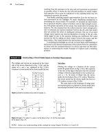
Calculating Voltage, Current, and Power for a Simple Resistive Circuit
In each circuit in Fig. 2.8, either the value of v or i is
not known.
Ml A*
8
0
50 V
T
0.2 S
(a)
(b)
Mi A ik 20a
50
V 25 0
. A
'ill
The current i
h
in the resistor with a conductance
of 0.2 S in Fig. 2.8(b) is in the direction of the
voltage drop across the resistor. Thus
i
h
= (50)(0.2) = 10 A.
The voltage v
c
in Fig. 2.8(c) is a rise in the direc-
tion of the current in the resistor. Hence
v
c
= -(1)(20) = -20 V.
The current i
d
in the 25 ft resistor in Fig. 2.8(d)
is in the direction of the voltage rise across the
resistor. Therefore
(c) (d)
Figure 2.8 • The circuits for Example 2.3.
a) Calculate the values of v and i.
b) Determine the power dissipated in each resistor.
Solution
a) The voltage v
a
in
Fig.
2.8(a) is a drop in the direc-
tion of the current in the resistor. Therefore,
q (1)(8)-8 V.
id
-50
25
= -2 A.
b) The power dissipated in each of the four resistors is
(8)
2
Pm =
P0.2S
=
P20O,
=
Pisa
=
(1)^(8) = 8 W,
(50)2(0.2) = 500 W,
(-20)"
20
(50)
2
25
= (1)2(20) = 20 W,
(-2)2(25) = 100 W.
^ASSESSMENT
PROBLEMS
Objective
2—Be
able to state and use Ohm's Law
2.3 For the circuit shown,
a) If v
g
= 1 kV and i
g
= 5 mA, find the value
of R and the power absorbed by the resistor.
b) If i
g
- 75 mA and the power delivered by
the voltage source is 3 W, find v
g
, R, and the
power absorbed by the resistor.
c) K
JR.
—
300 ft and the power absorbed by R
is 480 mW, find L and v
g
.
2.4 For the circuit shown,
a) If i
g
= 0.5 A and G = 50 mS, find v
g
and
the power delivered by the current source.
b) If v
g
- 15 V and the power delivered to the
conductor is 9 W, find the conductance G
and the source current L.
c) If G = 200 /xS and the power delivered to
the conductance is 8 W, find i
g
and v
g
.
*Q
:R
Answer: (a)200kQ,5W;
(b) 40
V,
533.33 ft, 3 W;
(c) 40 mA, 12 V
NOTE: Also try Chapter Problems 2.5 and 2.7.
Answer: (a)10V,5 W;
(b)40mS,0.6 A;
(c) 40 mA, 200 V.
34 Circuit Elements
Having introduced the general characteristics of ideal sources and resis-
tors,
we next show how to use these elements to build the circuit model of
a practical system.
2.3 Construction of a Circuit Model
We have already stated that one reason for an interest in the basic circuit
elements is that they can be used to construct circuit models of practical
systems.
The skill required to develop a circuit model of a device or system
is as complex as the skill required to solve the derived circuit. Although
this text emphasizes the skills required to solve circuits, you also will need
other skills in the practice of electrical engineering, and one of the most
important is modeling.
We develop circuit models in the next two examples. In Example 2.4
we construct a circuit model based on a knowledge of the behavior of the
system's components and how the components are interconnected. In
Example 2.5 we create a circuit model by measuring the terminal behavior
of a device.
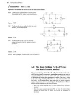
Example 2.4 Constructing a Circuit Model of a Flashlight
Construct a circuit model of a flashlight.
Solution
We chose the flashlight to illustrate a practical system
because its components are so familiar. Figure 2.9
shows a photograph of a widely available flashlight.
When a flashlight is regarded as an electrical
system, the components of primary interest are the
batteries, the lamp, the connector, the case, and the
switch. We now consider the circuit model for each
component.
A dry-cell battery maintains a reasonably con-
stant terminal voltage if the current demand is not
excessive. Thus if the dry-cell battery is operating
within its intended limits, we can model it with an
ideal voltage source. The prescribed voltage then is
constant and equal to the sum of two dry-cell values.
The ultimate output of the lamp is light energy,
which is achieved by heating the filament in the
lamp to a temperature high enough to cause radia-
tion in the visible range. We can model the lamp
with an ideal resistor. Note in this case that although
the resistor accounts for the amount of electric
energy converted to thermal energy, it does not pre-
dict how much of the thermal energy is converted to
light energy. The resistor used to represent the lamp
does predict the steady current drain on the batter-
ies,
a characteristic of the system that also is of inter-
est. In this model, R/ symbolizes the lamp resistance.
The connector used in the flashlight serves a
dual role. First, it provides an electrical conductive
path between the dry cells and the case. Second, it is
Figure 2.9 • A flashlight can be viewed as an electrical system.
formed into a springy coil so that it also can apply
mechanical pressure to the contact between the
batteries and the
lamp.
The purpose of this mechan-
ical pressure is to maintain contact between the two
dry cells and between the dry cells and the lamp.
Hence, in choosing the wire for the connector, we
may find that its mechanical properties are more
2.3 Construction of
a
Circuit Model 35
important than its electrical properties for the
flashlight design. Electrically, we can model the
connector with an ideal resistor, labeled R
{
.
The case also serves both a mechanical and an
electrical purpose. Mechanically, it contains all the
other components and provides a grip for the person
using it. Electrically, it provides a connection between
other elements in the flashlight. If the case is metal, it
conducts current between the batteries and the lamp.
If it is plastic, a metal strip inside the case connects
the coiled connector to the switch. Either way, an
ideal resistor, which we denote R
c
, models the electri-
cal connection provided by the case.
The final component is the switch. Electrically,
the switch is a two-state device. It is either
ON
or
OFF.
An ideal switch offers no resistance to the cur-
rent when it is in the
ON
state, but it offers infinite
resistance to current when it is in the
OFF
state.
These two states represent the limiting values of a
resistor; that is, the
ON
state corresponds to a resis-
tor with a numerical value of zero, and the
OFF
state
corresponds to a resistor with a numerical value of
infinity. The two extreme values have the descrip-
tive names short circuit (R = 0) and open circuit
(R = oo). Figure 2.10(a) and (b) show the graphical
representation of a short circuit and an open circuit,
respectively. The symbol shown in Fig. 2.10(c) rep-
resents the fact that a switch can be either a short
circuit or an open circuit, depending on the position
of its contacts.
We now construct the circuit model of the
flashlight. Starting with the dry-cell batteries, the
positive terminal of the first cell is connected to
the negative terminal of the second cell, as shown in
Fig.
2.11.
The positive terminal of the second cell is
connected to one terminal of the lamp. The other
terminal of the lamp makes contact with one side of
the switch, and the other side of the switch is con-
nected to the metal case.The metal case is then con-
nected to the negative terminal of the first dry cell
by means of the metal spring. Note that the ele-
ments form a closed path or circuit. You can see the
closed path formed by the connected elements in
Fig. 2.11. Figure 2.12 shows a circuit model for the
flashlight.
(a)
(b)
OFF
ON
(c)
Figure 2.10 • Circuit symbols, (a) Short circuit, (b) Open circuit,
(c) Switch.
Lamp
Filament
terminal
Dry cell # 2
Dry cell # 1
Sliding switch
Case
Figure 2.11 • The arrangement of flashlight components.
Figure 2.12 • A circuit model for a flashlight.
We can make some general observations about modeling from our
flashlight example: First, in developing a circuit model, the electrical behav-
ior of each physical component is of primary interest. In the flashlight
model, three very different physical components—a lamp, a coiled wire,
and a metal case—are all represented by the same circuit element (a resis-
tor),
because the electrical phenomenon taking place in each is the same.
Each is presenting resistance to the current flowing through the circuit.
Second, circuit models may need to account for undesired as well as
desired electrical effects. For example, the heat resulting from the resist-
ance in the lamp produces the light, a desired effect. However, the heat