Electric Circuits, 9th Edition P44 doc
Bạn đang xem bản rút gọn của tài liệu. Xem và tải ngay bản đầy đủ của tài liệu tại đây (583.23 KB, 10 trang )
406 Balanced Three-Phase Circuits
e) Calculate the phase voltages at the terminals of
the generator, V
an
, V
bn
, and V
cn
.
f) Calculate the line voltages V
ab
, V
bc
, and V
ca
at
the terminals of the generator.
g) Repeat (a)-(f) for a negative phase sequence.
Solution
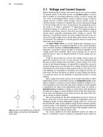
a) Figure 11.10 shows the single-phase equivalent
circuit.
b) The a-phase line current is
120
/0°
L
A
= <=
dA
(0.2 + 0.8 + 39) + /(0.5 + 1.5 + 28)
120
/0°
40
+ /30
= 2.4/-36.87°
A.
a'
0.2(2
/0-5
O
a
o.8(2 /1-50 A
f
'VW
^VYY>_
'.i A
©
120/0°
V V
an
39
n
1/28(1
Figure 11.10
A
The single-phase equivalent circuit
for
Example 11.1.
For
a
positive phase sequence,
I
bB
= 2.4
/-156.87°
A,
I
cC
= 2.4
/83.13°
A.
c)
The
phase voltage
at
the
A
terminal
of
the load
is
VAN
= (39 +
/28)(2.4/-36.87°)
= 115.22/-1.19°
V.
For
a
positive phase sequence,
V
BN
=
115.22/-121.19°
V,
V
CN
=
115.22/118.81°
V.
d)
For a
positive phase sequence,
the
line voltages
lead
the
phase voltages
by
30°; thus
VAB
=
(V3/30°)V
A
N
= 199.58 /28.81°
V,
V
BC
=
199.58/-91.19°
V,
V
C
A
=
199.58 /148.81°
V.
e) The phase voltage
at
the
a
terminal
of
the source
is
V
an
= 120 - (0.2 +
/0.5)(2.4/-36.87°)
=
120 -
1.29/31.33°
= 118.90 -/0.67
= 118.90/-0.32°
V.
For
a
positive phase sequence,
V
bn
=
118.90/-120.32°
V,
V
cn
=
118.90/119.68°
V.
f)
The
line voltages
at the
source terminals
are
Vab
=
(V5/30")V
a
n
- 205.94 /29.68°
V,
Vbc
=
205.94 /-90.32°
V,
V
ca
=
205.94/149.68°
V.
g) Changing
the
phase sequence
has no
effect
on
the single-phase equivalent circuit. The three line
currents
are
IaA
= 2.4
/-36.87°
A,
I,,
B
= 2.4
/83.13°
A,
I
cC
=
2.4/-156.87°
A.
The phase voltages
at the
load
are
V
AN
=
115.22/-1.19°
V,
V
BN
=
115.22/118.81°
V,
V
CN
=
115.22/-121.19°
V.
For
a
negative phase sequence,
the
line voltages
lag
the
phase voltages
by
30°:
V
AB
=
(V3/-30°)V
AN
- 199.58 /-31.19°
V,
V
BC
=
199.58 /88.81°
V,
VCA
=
199.58/-151.19°
V.
The phase voltages
at
the terminals
of
the gener-
ator
are
V
an
-
118.90/-0.32°
V,
V
bll
=
118.90/119.68°
V,
V
cn
=
118.90/-120.32°
V.
The line voltages
at the
terminals
of the
genera-
tor
are
V
ab
=
(V3/-30°)V
an
= 205.94/-30.32°
V,
V
bc
=
205.94 /89.68°
V,
V,,,
=
205.94/-150.32°
V.
11.4 Analysis of
the
Wye-Delta Circuit 407
^ASSESSMENT PROBLEMS
Objective 1—Know how to analyze a balanced, three-phase wye-wye circuit
11.1 The voltage from A to N in a balanced three-
phase circuit is 240 /—30° V. If the phase
sequence is positive, what is the value of V
BC
?
Answer: 415.69/-120
11.2
V.
The c-phase voltage of a balanced three-phase
Y-connected system is 450 /-25° V. If the
phase sequence is negative, what is the value
ofV
AB
?
Answer: 779.42 /65° V.
11.3 The phase voltage at the terminals of a bal-
anced three-phase Y-connected load is 2400 V.
The load has an impedance of 16 + /12 il/cp
and is fed from a line having an impedance of
0.10 + /0.80
Cl/cj).
The Y-connected source at
the sending end of the line has a phase
NOTE: Also try Chapter Problems 11.7,
11.9,
and
11.11.
sequence of acb and an internal impedance of
0.02 -I- /0.16 n/<£. Use the a-phase voltage at
the load as the reference and calculate (a) the
line currents I
aA
, I
bB
, and I
cC
; (b) the line volt-
ages at the source, V
ab
, V
bc
, and V
ca
; and (c) the
internal phase-to-neutral voltages at the source,
V
a
<n, V
b
-
n
, and V
c
-
n
.
Answer: (a) I
aA
= 120 /-36.87° A,
I
bB
= 120 /83.13° A, and
I
cC
= 120/-156.87° A;
(b) V
ab
= 4275.02 /-28.38° V,
V
bc
= 4275.02 /91.62° V, and
V
ca
= 4275.02 /-148.38° V;
(c) V
a
.
n
= 2482.05 /1.93° V,
V
b
-
n
= 2482.05 /121.93° V, and
V
c
'
n
= 2482.05/-118.07° V.
11.4 Analysis of the Wye-Delta Circuit
If the load in a three-phase circuit is connected in a delta, it can be trans-
formed into a wye by using the delta-to-wye transformation discussed in
Section 9.6. When the load is balanced, the impedance of each leg of the
wye is one third the impedance of each leg of the delta, or
Relationship between three-phase
delta-connected and wye-connected
-4 impedance
z - ~±
3
(11.21)
which follows directly from Eqs. 9.51-9.53. After the A load has been
replaced by its Y equivalent, the a-phase can be modeled by the single-
phase equivalent circuit shown in Fig.
11.11.
We use this circuit to calculate the line currents, and we then use the
line currents to find the currents in each leg of the original A load. The
relationship between the line currents and the currents in each leg of the
delta can be derived using the circuit shown in Fig. 11.12.
When a load (or source) is connected in a delta, the current in each leg
of the delta is the phase current, and the voltage across each leg is the
phase voltage. Figure 11.12 shows that, in the A configuration, the phase
voltage is identical to the line voltage.
To demonstrate the relationship between the phase currents and line
currents, we assume a positive phase sequence and let A/> represent the
magnitude of the phase current. Then
AB
cr
Ipc =/
A
/-HO".
l
rA
= At/120".
V
a
-
n
Zga
a
Zu
c
A
z
A
N
Figure 11.11 A
A
single-phase equivalent circuit.
(11.22)
(11.23) Figure 11.12 •
A
circuit used to establish the
relationship between line currents and phase currents in
(11-24) a balanced A load.
408 Balanced Three-Phase Circuits
Figure 11.13 • Phasor diagrams showing the
relationship between line currents and phase currents in
a A-connected
load,
(a) The positive sequence, (b) The
negative sequence.
In writing these equations, we arbitrarily selected I
AB
as the reference
phasor.
We can write the line currents in terms of the phase currents by direct
application of Kirchhoff s current law:
IaA
=
IAB ~ ICA
= I
A
/Q° -U/120*
=
V3I
4
/-30°,
IbB
=
IBC
-
IAB
= U /-120° - U.
= ^/^,/-150%
(11.25)
(11.26)
IcC
_
IcA ~~ IBC
= /,,/120° -/^/-120°
= y/3I
A
/90°.
(11.27)
Comparing Eqs. 11.25-11.27 with Eqs. 11.22-11.24 reveals that the magni-
tude of the line currents is V3 times the magnitude of the phase currents
and that the set of line currents lags the set of phase currents by 30°.
We leave to you to verify that, for a negative phase sequence, the line
currents are V3 times larger than the phase currents and lead the phase
currents by 30°. Thus, we have a shortcut for calculating line currents from
phase currents (or vice versa) for a balanced three-phase A-connected
load. Figure 11.13 summarizes this shortcut graphically. Example 11.2
illustrates the calculations involved in analyzing a balanced three-phase
circuit having a Y-connected source and a A-connected load.
Example 11.2
Analyzing a Wye-Delta Circuit
The Y-connected source in Example 11.1 feeds a
A-connected load through a distribution line hav-
ing an impedance of 0.3 + /0.9
Q,/4>.
The load
impedance is 118.5 + /85.8
Cl/4>.
Use the a-phase
internal voltage of the generator as the reference.
a) Construct a single-phase equivalent circuit of the
three-phase system.
b) Calculate the line currents I
aA
, I
bB
, and I
cC
.
c) Calculate the phase voltages at the load terminals.
d) Calculate the phase currents of the load.
e) Calculate the line voltages at the source terminals.
Solution
a) Figure 11.14 shows the single-phase equivalent
circuit. The load impedance of the Y equivalent is
118.5 + /85.8
= 39.5 + /28.6 ft/0.
a' 0.212 /0.511
a
0.3 ft
/0.9
0 A
C_J 120/0°
39.5 ft
/28.6 ft
N
Figure 11.14 • The single-phase equivalent circuit for
Example 11.2.
b) The a-phase line current is
120 /C
IaA =
(0.2 + 0.3 + 39.5) + /(0.5 + 0.9 + 28.6)
120/0°
rr ~- = 2.4 /-36.87° A.
40 + /30
z
11.4 Analysis of
the
Wye-Delta Circuit 409
Hence
I
bB
= 2.4/-156.87° A,
I
cC
= 2.4 /83.13° A.
c) Because the load is A connected, the phase volt-
ages are the same as the line voltages. To calcu-
late the line voltages, we first calculate V
AN
:
VAN
= (39.5 + /28.6)(2.4/-36.87°)
= 117.04/-0.96° V.
Because the phase sequence is positive, the line
voltage
VAB
*
S
VAB = (V5/30')V
A
N
= 202.72 /29.04° V.
Therefore
V
BC
= 202.72 /-90.96° V,
V
CA
= 202.72 /149.04° V.
d) The phase currents of the load may be calculated
directly from the line currents:
l
AB
1
V3
/30'
aA
=
1.39/-6.87°
A.
Once we know I
AB
, we also know the other load
phase currents:
I
BC
=
1.39/-126.87°
A,
I
CA
=
1.39/113.13°
A.
Note that we can check the calculation of I
AB
by
using the previously calculated V
A
B
ar
>d the
impedance of the A-connected load; that is,
V
AB
_ 202.72/29.04°
IAB
~" ~Z^ ' 118.5 +/85.8
=
1.39/-6.87°
A.
e) To calculate the line voltage at the terminals of
the source, we first calculate V
an
. Figure 11.14
shows that V
an
is the voltage drop across the line
impedance plus the load impedance, so
V
an
= (39.8 + /29.5)(2.4/-36.87°)
= 118.90/-0.32° V.
The line voltage V
ab
is
V
ab
= (V3~/30°)V
an
,
or
V
ab
= 205.94 /29.68° V.
Therefore
V
bc
= 205.94/-90.32° V,
V
ca
= 205.94/149.68° V.
^ASSESSMENT PROBLEMS
Objective 2—Know how to analyze a balanced, three-phase wye-delta connected circuit
11.4 The current I
CA
in a balanced three-phase
A-connected load is 8 /—15° A. If the phase
sequence is positive, what is the value of
I
cC
?
Answer: 13.86/-45° A.
11.5 A balanced three-phase A-connected load is
fed from a balanced three-phase circuit. The
reference for the b-phase line current is toward
the load. The value of the current in the
b-phase is 12 /65° A. If the phase sequence is
negative, what is the value of I
A
B?
Answer: 6.93 /-85° A.
11.6 The line voltage
V
A
B
at the terminals of a bal-
anced three-phase A-connected load is
4160 /0° V. The line current I
aA
is
69.28/-10° A.
a) Calculate the per-phase impedance of the
load if the phase sequence is positive.
b) Repeat (a) for a negative phase sequence.
Answer: (a) 104 /-20° H;
(b) 104/+40° a.
11.7 The line voltage at the terminals of a balanced
A-connected load is 110
V.
Each phase of the
load consists of a 3.667 II resistor in parallel with
a 2.75
Cl
inductive impedance. What is the mag-
nitude of the current in the line feeding the load?
Answer: 86.60 A.
NOTE: Also try Chapter Problems 11.12,11.13, and 11.16.
410
Balanced Three-Phase Circuits
IaA
%B
*•
Ice'
B
+
v
BN
^B
z
A
—
C
i
Ts
»
i\
Z
c
Figure
11.15 •
A
balanced
Y
load used to introduce
average
power
calculations
in three-phase circuits.
11.5
Power Calculations in Balanced
Three-Phase
Circuits
So far, we have limited our analysis of balanced three-phase circuits to
determining currents and voltages. We now discuss three-phase power
calculations. We begin by considering the average power delivered to a
balanced Y-connected load.
Average Power in a Balanced Wye Load
Figure 11.15 shows a Y-connected load, along with its pertinent currents and
voltages. We calculate the average power associated with any one phase by
using the techniques introduced in Chapter
10.
With Eq. 10.21 as a starting
point, we express the average power associated with the a-phase as
^A = |V
AN
||I
aA
|cos(t9
vA
-M,
(11.28)
where 8„
A
and 0,
A
denote the phase angles of V
AN
and I
uA
, respectively.
Using the notation introduced in Eq. 11.28, we can find the power associ-
ated with the b- and c-phases:
Pa = |V
B
Nl|IbBl«>s(0vB-0/B);
Pc = !V
CN
||I
cC
|cos(f\
c
-0;
C
).
(11.29)
(11.30)
In Eqs. 11.28-11.30, all phasor currents and voltages are written in terms
of the rms value of the sinusoidal function they represent.
In a balanced three-phase system, the magnitude of each line-to-neutral
voltage is the same, as is the magnitude of each phase current. The argu-
ment of the cosine functions is also the same for all three phases. We
emphasize these observations by introducing the following notation:
and
V
d
, = |V
AN
| =
|VBNI
=
IVCNI,
(11.31)
(11.32)
(11.33)
Moreover, for a balanced system, the power delivered to each phase of the
load is the same, so
PA = PB = PC = P* = V^ cos ^,
(11.34)
where P^ represents the average power per phase.
The total average power delivered to the balanced Y-connected load
is simply three times the power per phase, or
P
T
= 3P
4)
= 3V
<h
I
(!)
cosO
(11.35)
Expressing the total power in terms of the rms magnitudes of the line volt-
age and current is also desirable. If we let V
L
and I
L
represent the rms
magnitudes of the line voltage and current, respectively, we can modify
Eq. 11.35 as follows:
Total
real power in a balanced
three-phase
load •
3
(^)
/LC
°
!
4>
V3V
L
/
L
cos^.
(11.36)
11.5 Power Calculations in Balanced Three-Phase Circuits 411
In deriving Eq. 11.36, we recognized that, for a balanced Y-connected
load, the magnitude of the phase voltage is the magnitude of the line volt-
age divided by V5, and that the magnitude of the line current is equal to
the magnitude of the phase current. When using Eq. 11.36 to calculate the
total power delivered to the load, remember that 0$ is the phase angle
between the phase voltage and current.
Complex Power in a Balanced Wye Load
We can also calculate the reactive power and complex power associated
with any one phase of a Y-connected load by using the techniques intro-
duced in Chapter 10. For a balanced load, the expressions for the reactive
power are
2r = 3Q^ = V3V
L
/
L
sin^.
(11.37)
(11.38)
Equation 10.29 is the basis for expressing the complex power associated
with any phase. For a balanced load,
S<t>
- ^AN^aA
_
^BNlbB ~ V
CN
IcC
v;
(11.39)
where V^ and 1^, represent a phase voltage and current taken from the
same phase. Thus, in general,
(11.40)
(11.41)
< Total reactive power in a balanced
three-phase load
-4 Total complex power in a balanced three-
phase load
Power Calculations in a Balanced Delta Load
If the load is A-connected, the calculation of power—reactive or complex-
is basically the same as that for a Y-connected load. Figure 11.16 shows a
A-connected load, along with its pertinent currents and voltages. The
power associated with each phase is
^A
=
|V
A
BI|IAB|COS(0
VAB
-
0
/AB
),
PB = |VBCI|IBC|C°S(0
V
BC "
0
'-BC)»
^c = |V
C
AI|ICA|COS(0
VCA
-0
(CA
).
For a balanced load,
|V
AB
| =
IVBCI
=
IVCAI
= V*
HABI
=
IIBCI
=
IICAI
= /*
0<AB
=
#t>BC ~ ^/BC
=
^«CA
e
vAB rCA
=
0.,
and
P
A
= PB = Pc =
Pd>
= K^cos^.
Note that Eq. 11.48 is the same as Eq. 11.34. Thus, in a balanced load,
regardless of whether it
is Y-
or A-connected, the average power per phase
is equal to the product of the rms magnitude of the phase voltage, the rms
magnitude of the phase current, and the cosine of the angle between the
phase voltage and current.
B L
Z
A
V,-
CA
(11.42)
(11.43)
(11.44)
VM
(11.45)
Figure 11.16 •
A
A-connected load used to discuss
(11.46) power calculations.
(11.47)
(11.48)
The total power delivered to a balanced A-connected load is
P
r
= 3^ =
31^
cos 0*
= V3V
L
/
L
cos0*. (11-49)
Note that Eq. 11.49 is the same as Eq. 11.36. The expressions for reactive
power and complex power also have the same form as those developed for
the Y load:
Q^
=
V
4>
I
lf>
sme
4>
; (11.50)
Qr = 3Q* = 3VV
0
sin
$+; (11.51)
S<i>
=
P<i>
+
jQ^>
= V^lJ;
(11.52)
S
T
=
3S
lb
= V3V
L
I
L
/$£.
(11.53)
Instantaneous Power in Three-Phase Circuits
Although we are primarily interested in average, reactive, and complex
power calculations, the computation of the total instantaneous power is
also important. In a balanced three-phase circuit, this power has an inter-
esting property: It is invariant with time! Thus the torque developed at the
shaft of a three-phase motor is constant, which in turn means less vibra-
tion in machinery powered by three-phase motors.
Let the instantaneous line-to-neutral voltage v
AN
be the reference,
and, as before, 0^ is the phase angle 0„
A
—
0
/A
. Then, for a positive phase
sequence, the instantaneous power in each phase is
PA
=
v
AN
i
aA
=
V
m
I
m
cos
art
cos
(a>t
- 0
4
),
PB
=
V
BNA>B
=
V,„I
m
cos
(art
- 120°) cos
(a>t
-0,/,-
120°),
Pc =
UCN'CC
=
V
in
I
m
cos(a)t
+ 120°) cos
(art
-0^,+ 120°),
where V
m
and I
m
represent the maximum amplitude of the phase voltage
and line current, respectively. The total instantaneous power is the sum of
the instantaneous phase powers, which reduces to 1.5V
m
I
m
cos 9^, that is,
PT
= PA + PB + Pc = 1.5V
lfI
/
m
cos00.
Note this result is consistent with Eq. 11.35 since V
m
= V2~V'$ and
I
m
= V2/^ (see Problem 11.26).
Examples 11.3-11.5 illustrate power calculations in balanced three-
phase circuits.
V3
cos0
rf
11.5 Power Calculations in Balanced Three-Phase Circuits 413
Example 11.3 Calculating Power in a Three-Phase Wye-Wye Circuit
a) Calculate the average power per phase delivered
to the Y-connected load of Example 11.1.
b) Calculate the total average power delivered to
the load.
c) Calculate the total average power lost in the line.
d) Calculate the total average power lost in the
generator.
e) Calculate the total number of magnetizing vars
absorbed by the load.
f) Calculate the total complex power delivered by
the source.
Solution
a) From Example
11.1,
V^ = 115.22 V, I
4
= 2.4 A,
and 0^ = -1.19 - (-36.87) =
35.68°.
Therefore
?$ = (115.22)(2.4) cos 35.68'
= 224.64 W.
The power per phase may also be calculated
from l\R^ or
P+ = (2.4)
2
(39) = 224.64 W.
b) The total average power delivered to the load is
p
T
= 3/^ = 673.92 W. We calculated the line
voltage in Example 11.1, so we may also use
Eq. 11.36:
P
T
= V3(199.58)(2.4) cos 35.68°
= 673.92 W.
c) The total power lost in the line is
P
Vme
= 3(2.4)
2
(0.8) = 13.824 W.
d) The total internal power lost in the generator is
gen
3(2.4)2(0.2) = 3.456 W.
c) The total number of magnetizing vars absorbed
by the load is
Q
T
= V5( 199.58)(2.4) sin 35.68°
= 483.84 VAR.
f) The total complex power associated with the
source is
S
T
= 3St = -3(120)(2.4) /36.87°
= -691.20 -/518.40 VA.
The minus sign indicates that the internal power
and magnetizing reactive power are being deliv-
ered to the circuit. We check this result by calcu-
lating the total and reactive power absorbed by
the circuit:
P = 673.92 + 13.824 + 3.456
= 691.20 W (check),
Q = 483.84 + 3(2.4)
2
(1.5) + 3(2.4)
2
(0.5)
= 483.84 + 25.92 + 8.64
= 518.40 VAR(check).
Example 11.4
Calculating Power in a Three-Phase Wye-Delta Circuit
a) Calculate the total complex power delivered to
the A-connected load of Example 11.2.
b) What percentage of the average power at the
sending end of the line is delivered to the load?
Solution
a) Using the a-phase values from the solution of
Example 11.2, we obtain
V^ = V
AB
= 202.72 /29.04° V,
Ia = I
AB
= 139/-6.87
a
A.
Using Eqs. 11.52 and
11.53,
we have
S
T
= 3(202.72 /29.04° )(1.39 /6.87°)
= 682.56 + /494.21 VA.
b) The total power at the sending end of the distri-
bution line equals the total power delivered to
the load plus the total power lost in the line;
therefore
/»
input
= 682.56 + 3(2.4)2(0.3)
= 687.74 W.
The percentage of the average power reaching
the load is 682.56/687.74, or 99.25%. Nearly
100%
of the average power at the input is
delivered to the load because the impedance of
the line is quite small compared to the load
impedance.
414 Balanced Three-Phase Circuits
Example 11.5
Calculating Three-Phase Power with an Unspecified Load
A balanced three-phase load requires 480 kW at a
lagging power factor of 0.8. The load is fed from a
line having an impedance of 0.005 + /0.025 0/<£.
The line voltage at the terminals of the load is 600 V.
a) Construct a single-phase equivalent circuit of
the system.
b) Calculate the magnitude of the line current.
c) Calculate the magnitude of the line voltage at
the sending end of the line.
d) Calculate the power factor at the sending end of
the line.
Solution
a) Figure 11.17 shows the single-phase equivalent
circuit. We arbitrarily selected the line-to-neutral
voltage at the load as the reference.
0.005 n /0.025 n
a • 'VW— —<'Y^'Y-^
9 A
+
fa*
•—
"C
600
+
—«
»N
160
kW
at 0.8 lag
Figure 11.17 •
The
single-phase equivalent circuit for
Example 11.5.
b) The line current I*
A
is given by
600
V3
IaA = (160 + /120)10
3
,
or
IaA = 577.35 /36.87° A.
Therefore, I
aA
= 577.35 /-36.87° A. The mag-
nitude of the line current is the magnitude of I
aA
:
I
L
= 577.35 A.
We obtain an alternative solution for I
L
from
the expression
p
r
h.
= V3V
L
I
L
cosB
p
= V3(600)/
L
(0.8)
= 480,000 W;
480,000
V3(600)(0.8)
1000
V3
= 577.35 A.
c) To calculate the magnitude of the line voltage at
the sending end, we first calculate V
an
. From
Fig. 11.17,
V
n
AN
600
+ Z,l
(HA
-z= + (0.005 + /0.025)(577.35/-36.87°)
= 357.51 /1.57° V.
Thus
V
L
= V3|V
:
J
= 619.23 V.
d) The power factor at the sending end of the line
is the cosine of the phase angle between V
an
and I
aA
:
pf = cos [1.57° - (-36.87°)]
= cos 38.44°
= 0.783 lagging.
An alternative method for calculating the power
factor is to first calculate the complex power at
the sending end of the line:
S
(b
= (160 + /12())10
3
+ (577.35)
2
(0.005 + /0.025)
= 161.67 +/128.33 kVA
= 206.41 /38.44° kVA.
The power factor is
pf = cos 38.44°
= 0.783 lagging.
Finally, if we calculate the total complex power
at the sending end, after first calculating the
magnitude of the line current, we may use this
value to calculate V
L
. That is,
V3VJ
L
= 3(206.41) x 10
3
,
3(206.41) X 10
3
Vi =
V3(577.35) '
= 619.23 V.
11.6 Measuring Average Power in Three-Phase Circuits 415
^ASSESSMENT PROBLEMS
Objective 3—Be able to calculate power (average, reactive, and complex) in any three-phase circuit
11.8 The three-phase average power rating of the
central processing unit (CPU) on a mainframe
digital computer is 22,659
W.
The three-phase
line supplying the computer has a line voltage
rating of 208 V
(rms).
The line current is 73.8 A
(rms).The computer absorbs magnetizing VARs.
a) Calculate the total magnetizing reactive
power absorbed by the CPU.
b) Calculate the power factor.
Answer: (a) 13,909.50 VAR;
(b) 0.852 lagging.
NOTE: Also try Chapter Problems 11.22 and 11.24.
11.9 The complex power associated with each phase
of a balanced load is 144 + /192 kVA. The line
voltage at the terminals of the load is 2450 V.
a) What is the magnitude of the line current
feeding the load?
b) The load is delta connected, and the imped-
ance of each phase consists of a resistance in
parallel with a reactance. Calculate R and X.
c) The load is wye connected, and the imped-
ance of each phase consists of a resistance in
series with a reactance. Calculate R and X.
Answer: (a) 169.67 A;
(b)R = 41.68 ft, X = 31.26 ft;
(c) R = 5 ft, X = 6.67 ft.
11.6 Measuring Average Power
in Three-Phase Circuits
The basic instrument used to measure power in three-phase circuits is the
electrodynamometer wattmeter. It contains two coils. One coil, called the
current coil, is stationary and is designed to carry a current proportional to
the load current. The second coil, called the potential coil, is movable and
carries a current proportional to the load voltage. The important features
of the wattmeter are shown in Fig. 11.18.
The average deflection of the pointer attached to the movable coil is
proportional to the product of the effective value of the current in the cur-
rent coil, the effective value of the voltage impressed on the potential coil,
and the cosine of the phase angle between the voltage and current. The
direction in which the pointer deflects depends on the instantaneous polar-
ity of the current-coil current and the potential-coil voltage.Therefore each
coil has one terminal with a polarity mark —usually a plus sign—but some-
times the double polarity mark ± is used. The wattmeter deflects upscale
when (1) the polarity-marked terminal of the current coil is toward the
source, and (2) the polarity-marked terminal of the potential coil is con-
nected to the same line in which the current coil has been inserted.
The Two-Wattmeter Method
Consider a general network inside a box to which power is supplied by
n conducting lines. Such a system is shown in Fig. 11.19.
If we wish to measure the total power at the terminals of the box, we
need to know n — 1 currents and voltages. This follows because if we
choose one terminal as a reference, there are only n - 1 independent
voltages. Likewise, only n —
1
independent currents can exist in the n con-
ductors entering the
box.
Thus the total power is the sum of n —
1
product
terms;
that is, p = v
x
i\ + v
2
t2 +
• • •
+
t>
fl
_
r
L_j.
Watt
scale
Current-coil
terminals
Potential-coil
terminals
Pointer
Figure 11.18 • The key features of the
electrodynamometer wattmeter.


