- Trang chủ >>
- Khoa Học Tự Nhiên >>
- Vật lý
Basic Theoretical Physics: A Concise Overview P19 ppt
Bạn đang xem bản rút gọn của tài liệu. Xem và tải ngay bản đầy đủ của tài liệu tại đây (255.04 KB, 10 trang )
21.1 Introduction: Wave Equations; Group and Phase Velocity 181
where n (=
√
ε ·μ)istherefractive index
2
. In optically dense light-trans-
mitting media (e.g., glass or water) n is significantly > 1, which gives rise to
the well-known phenomenon of refraction described by Snell’s law:
sin α
1
sin α
2
=
n
2
n
1
.
This expression describes the refraction of light rays at a plane boundary
between a vacuum with refractive index n = 1 (or in practice: air) and an
(optically) denser medium with n
2
> 1. The angle of incidence from the
vacuum is α
1
.
The refractive index, n, is thus related both to the (relative) dielectric
constant of the material, ε
r
, and also to the (relative) permeability μ
r
3
.This
also means that generally n depends on the wavenumber k and frequency ω.
The above relation for dielectric and/or permeable matter follows from
Maxwell’s equations in the absence of charges and currents (i.e., for
≡ j ≡ 0):
divε
r
ε
0
E = ≡ 0;divB =0;
curlE = −
∂B
∂t
;curl
B
μ
r
μ
0
= j + ε
r
ε
0
∂E
∂t
. (21.2)
Applying the operator curl to the third and fourth equations, together
with the identity
curl curlv =graddivv −∇
2
v
we obtain the following wave equations:
∇
2
−
1
c
2
m
(∂
t
)
2
E =0 and
∇
2
−
1
c
2
m
(∂
t
)
2
B =0,
where c
m
(see below) is the velocity of a stationary electromagnetic wave in
the considered medium.
Similar wave equations occur in other cases, e.g., for transverse sound
waves (shear waves, → transverse phonons in solid state physics) it is only
necessary to replace E and cB by the transverse displacements of the atoms
from their rest positions and the velocity of light, c
m
, by the transverse sound
velocity c
(s)
⊥
(which in metals is of the order of 10
3
m/s). With these re-
placements one obtains the same wave equation in totally different contexts.
(There are also longitudinal sound waves (compression waves
4
, → longitudi-
nal phonons) with a significantly higher sound velocity c
(s)
long.
.)
2
In some (mainly artificial) materials both ε and μ are negative, i.e., also n.These
so-called left-handed materials have unusual optical properties.
3
To avoid any misunderstanding, here we explicitly use the lower index
r
, although
hitherto we did not use this convention.
4
In liquids and gases only compression waves exist, and not shear waves.
182 21 Applications of Electrodynamics in the Field of Optics
The relationship
ω = ω(k)
between frequency ω and wavenumber k
5
is referred to as the dispersion
relation.
For light waves in vacuo the dispersion relation is simply ω = c
0
·|k|.
In polarizable matter, light waves have only apparently almost the same
dispersion behavior. It is true that often ω = c
m
·|k|, but even then the light
velocity in matter,
c
m
= c
0
/
ε
r
(ω) · μ
r
(ω) ,
generally depends on the same frequency ω that one wishes to calculate
6
,so
that it makes sense to distinguish between the so-called phase velocity
v
phase
=
ω
k
e
k
and the group velocity
v
group
=grad
k
ω(k) .
As a consequence, the components of the group velocity v
group
are calcu-
lated as follows:
(v
group
)
i
=
∂ω(k)
∂k
i
. (21.3)
The group velocity can thus have a different direction from the wavenumber
k (see below, e.g., the term ray velocity in the subsection on birefringence in
crystals).
As an example for the difference between phase velocity and group veloc-
ity consider transverse sound waves propagating in an ideal crystal of cubic
symmetry with lattice constant a.Letk be parallel to an edge direction.
One then obtains transverse elastic plane waves with the following dispersion
relation:
ω(k)=c
(s)
⊥
sin
k·a
2
a
2
. (21.4)
Thus, if the wavelength λ is much larger than the lattice constant a, i.e.,
for k ·a 1, we have, as expected:
ω = c
(s)
⊥
k,
and the group velocity,
|v
group
| ,
5
k =
2π
λ
e
k
,whereλ is the wavelength and e
k
the propagation direction of the
plane wave, i.e., according to the usual ansatz Ψ ∝Re exp(i(k · r − ωt)).
6
The frequency dependence of the light velocity may involve not only the ampli-
tude, but also the direction (see below).
21.1 Introduction: Wave Equations; Group and Phase Velocity 183
and phase velocity, c
(s)
⊥
, are identical; but for k ·a → π, i.e., with decreasing
λ → 2a,thegroup velocity converges to zero,
∂ω
∂k
→ 0 .
The meaning of “group velocity” can be illustrated by considering a wave
packet generated by the superposition of monochromatic plane waves with
slightly different k-vectors in the interval Δk:
Ψ(x, t)=
Δk
dka(k)e
i(k·x−ω(k)·t)
. (21.5)
One obtains beats, which can be treated by a Taylor expansion, as follows:
If K
0
is the center of the interval Δk, i.e.,
k = K
0
+ k
(with k
∈
−
K
0
2
, +
K
0
2
)thenwehavea(k) ≈ a(K
0
)and
ω(k) · t ≈ ω(K
0
) · t + k
dω
dk
· t + .
Thus
Ψ(x, t) ≈ a(K
0
)e
i(K
0
x−ω(K
0
)·t)
K
0
2
−
K
0
2
dk
e
ik
·(x−v
group
·t)
. (21.6)
The factor immediately in front of the integral, which can also be written
as e
iK
0
·(x−v
phase
t)
(i.e., with the phase velocity v
phase
) describes the rapid os-
cillation of the amplitude of the wave. In contrast, the integral itself describes
the (much slower) wave motion of an envelope function, which is propagated
at the group velocity v
group
;inparticularwehave
|Ψ(x, t)|
2
∝|a(K
0
)|
2
·
K
0
2
−
K
0
2
dk
e
ik
·(x−v
group
·t)
2
. (21.7)
The transport of energy in a wave packet propagates with the group veloc-
ity, not the phase velocity, and according to Einstein’s theory of relativity we
have the constraint that |v
group
| (and not |v
phase
|) must always be ≤ c (see
below).
The difference between phase velocity and group velocity becomes clear
if we consider an electromagnetic wave reflected “back and forth” between
two metal plates perfectly parallel to the plane z ≡ 0. (These parallel plates
184 21 Applications of Electrodynamics in the Field of Optics
form the simplest version of a waveguide.) We assume that this guided elec-
tromagnetic wave propagates in the x-direction. The phase velocity is given
by
(v
phase
)
x
=
c
cos θ
, which is >c.
In contrast, the group velocity is
(v
group
)
x
= c ·cos θ, i.e. , ≤ c,
as expected. Here θ is the grazing angle at which the electromagnetic wave
meets the metal plates.
In the context of our treatment of phase and group velocity we should
mention not only Planck’s radiation formula (1900, see above) but also Ein-
stein’s “photon” hypothesis (1905, see below), which essentially resolved the
problem of whether light should be considered as a particle phenomenon
(Newton) or a wave phenomenon (Huygens). The answer is “both” (→ wave-
particle duality, see Part III). According to Einstein (1905, → Nobel prize
1921) electromagnetic waves result from the emission of individual relativistic
quanta with velocity c (→ “photons”, see below), possessing energy E = hν,
momentum
p =
E
c
=
hν
c
(= k) ,
and vanishing rest mass. The internal energy U (T ) of the electromagnetic
field in a large cavity of volume V at Kelvin temperature T is then (see
above, and Parts III and IV) given according to Planck’s formula:
U(T )=V ·
∞
ν=0
8πν
2
dν
c
3
·
hν
exp
hν
k
B
T
− 1
, (21.8)
where the factor
V ·
8πν
2
dν
c
3
is the number of wave modes with frequencies ν ∈ dν; hν is the energy of
a single photon of wavelength
c
ν
, and the thermal expectation value n
ν
of
the number of these photons is
n
ν
=
∞
n=0
n · e
−n
hν
k
B
T
∞
n=0
e
−n
hν
k
B
T
=
1
exp
hν
k
B
T
− 1
.
(k
B
is Boltzmann’s constant.)
21.2 From Wave Optics to Geometrical Optics; Fermat’s Principle 185
If in this formula the integration variable
8πν
2
dν
c
3
is replaced by the more general expression
e
f
·
d
3
k
(2π)
3
,
where for photons the degeneracy factor e
f
has the value 2 and the function
ω(k)=c · k
has to be used, then Planck’s formula can be generalized.
For example, for the excitations of so-called quasi-particles resembling
photons, e.g. for “phonons” or “magnons” (the quanta of sound waves and
of spin waves, respectively) or for “plasmons” (quanta corresponding to os-
cillations of the charge density in solids), one has similar properties as for
photons, but different dispersion relations (e.g. ω(k)=D ·k
2
for magnons in
ferromagnets and
ω(k)=ω
p
+ b · k
2
for plasmons,whereω
p
is the plasma frequency and b a positive factor.)
Thus in analogous manner to that for photons one obtains different results
for the internal energy U(T ) of the quasi-particle gas considered. One sees
here that the dispersion relation ω(k) of a wave plays an important role not
only in optics but also in many other branches of physics.
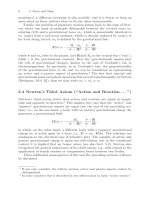
21.2 From Wave Optics to Geometrical Optics;
Fermat’s Principle
By avoiding abrupt changes (e.g., by neglecting such quantities as
|λ · gradA(r)| ,
see below) one can start with wave optics and arrive at the field of geometrical
or ray optics as follows.
Commencing with the wave equation
∇
2
−
1
c
m
2
∂
tt
Ψ(r,t)=0, (21.9)
where Ψ is one of the Cartesian components of the electromagnetic fields
or one of the equivalent wave quantities considered
7
,wetrytosolvethis
7
Neglecting the vectorial character of the electromagnetic field is already an ap-
proximation, the so-called scalar approximation. This can already be essential,
which should not be forgotten.
186 21 Applications of Electrodynamics in the Field of Optics
equation with the usual stationary ansatz. Thus we are led to the following
wave equation:
∇
2
+ k
2
(r)
ψ(r)
!
=0, (21.10)
with
k(r)=
ω
c
m
= k
0
· n(r) ,
where k
0
=
ω
c
0
and n(r) is the refractive index, which is a real quantity (see
above). For cases involving dielectric losses or for Ohmic behavior, one should
replace n(r)bythecomplexquantity
˜n := n +iκ, where κ
−1
is the absorption length.
The solution is now
ψ(r):=A(r) · exp ik
0
· S(r) ,
with the so-called eikonal S(r). In spite of its strange name, which has mainly
historical reasons, this function S is most important for geometrical optics;
it has the dimensionality of an effective length, viz the minimum distance
between two equivalent wave fronts.
8
One now assumes that with the formation of the second derivatives the
terms ∝ k
2
0
dominate, e.g.,
∂
2
ψ
∂x
2
≈−k
2
0
(
∂S
∂x
)
2
ψ + ,
where the dots represent neglected terms, which are not proportional to k
2
0
,
but only to the first or zeroth power of k
0
.
9
In this way the wave equation
(21.10) is systematically replaced by the so-called eikonal equation
10
(gradS(r))
2
≈ n(r)
2
. (21.11)
Here the surfaces S(r)=constant describe the wave fronts,andtheir
gradients describes the ray directions.
The eikonal approximation of a scalar wave equation, derived from
Maxwell’s theory, is the basis of geometrical (or ray) optics. In particular
one can derive from it Fermat’s principle of the “shortest optical path”:
r
2
r
1
dln(r)
!
= min (21.12)
8
The eikonal function S(r) should of course not be confused with the Poynting
vector S or the entropy S(T ) of statistical physics (Part IV). In each of these
cases the same letter S is used.
9
Note that k
0
is not small, but large (k
0
=
2π
λ
0
,whereλ
0
is the wavelength).
10
A similar approximation leads from Schr¨odinger’s wave equation of quantum
mechanics to the Hamilton-Jacobi equations of classical mechanics (see below).
21.2 From Wave Optics to Geometrical Optics; Fermat’s Principle 187
for the real path of a ray of light. Due to lack of space, further details on
Fermat’s principle will not be described here. We only mention that not only
Snell’s law of refraction (see above), but essentially the whole of lense optics,
including optical microscopy, can be derived from it.
11
The eikonal approximation is significant because it contains the transition
from (i) the wave picture of light, explored by Huygens and Young (with the
basic issue of the ability to interfere; → holography, see below) to the (ii)
particle representation.
In the particle representation, light rays without the ability to interfere
are interpreted as particle trajectories, while the wave fronts S(r) are inter-
preted as purely fictitious mathematical quantities. This is analogous to the
transition from quantum mechanics to classical mechanics in semiclassical
theories: one tries to solve the Schr¨odinger equation
−
2
2m
∇
2
ψ + V (r)ψ = Eψ ,
which plays the role of a matter-wave equation,byakindofeikonal ansatz,
ψ(r):=A(r) · exp
i
S(r) .
(Here S(r) has the dimensionality of action, i.e., the same dimensionality
as Planck’s constant h ( is Planck’s constant divided by (2π).) An expansion
in powers of
1
(taking into account only the dominant terms analogously
to the eikonal ansatz ) leads to the so-called Hamilton-Jakobi equations of
classical mechanics, viz
(gradS)
2
2m
+ V (r) ≡ E.
The Hamilton-Jakobi equation contains the totality of classical mechan-
ics, e.g., the Hamilton function, the canonical equations and also Hamilton’s
principle of least action, which ultimately corresponds to Fermat’s princi-
ple.
12
11
See, e.g., Fliessbach’s book on electrodynamics, problem 36.2
12
The equivalence can be rather easily shown: Hamilton’s principle says that
R
t
2
t
1
dtL
!
≡ extremal for variation of all virtual orbits in the space of gen-
eralized coordinates q
i
, for fixed initial and final coordinates. (The momenta
p
i
≡ ∂L/∂ ˙q
i
result implicitly). Using a Legendre transformation, one replaces
L(q
i
, ˙q
i
) →
P
i
p
i
˙q
i
−H, with the Hamilton function H(p
i
,q
k
), where the gener-
alized coordinates and momenta are varied independently. Meanwhile one sub-
stitutes H by the constant E, i.e., one does not vary all orbits in phase space,
but only those with constant H≡E. In this way one obtains the so-called Mau-
pertuis principle (→ Landau-Lifshitz I, [13], Chap. 44) of classical mechanics. In
the field of optics, it corresponds exactly to Fermat’s principle.
188 21 Applications of Electrodynamics in the Field of Optics
21.3 Crystal Optics and Birefringence
For (i) fluids (gases and liquids), (ii) polycrystalline solids, (iii) amorphous
substances and (iv) cubic crystals, the dielectric displacement D is propor-
tional to E, i.e., as assumed hitherto:
D = ε
r
ε
0
E .
In contrast, for non-cubic crystals plus all solid systems under strong uniaxial
tension or compression, the behavior is more complicated. For such systems
we have (for i =1, 2, 3)
D
i
=
3
k=1
ε
i,k
ε
0
E
k
, (21.13)
where the dielectric constants ε
i,k
now form a tensor.
In the following we shall assume (i) that we are dealing with nonmagnetic
material, such that the relative permeability is 1, and (ii) that there are no
magnetic fields, such that
ε
i,k
≡ ε
k,i
The tensor ε
i,k
can be diagonalized by a suitable rotation, i.e., in the new
orthogonal basis it has the diagonal representation
ε
α,β
=
⎛
⎝
ε
1
, 0 , 0
0 ,ε
2
, 0
0 , 0 ,ε
3
⎞
⎠
. (21.14)
The quadratic form
w
e
=
1
2
E ·D ≡
ε
0
2
3
i
,k=1
ε
i,k
E
i
E
k
is thus diagonal in the eigenvector basis, i.e., there are analogous relations as
for the mechanical rotational energy of a rigid body (see Part I).
The relation
w
e
=
1
2
E ·D
for the energy density of the electric field corresponds in fact to the mechan-
ical relation
T
Rot
=
1
2
ω ·L ,
and the mechanical relation
L
i
=
3
k=1
Θ
i,k
ω
k
,
21.3 Crystal Optics and Birefringence 189
with the components Θ
i,k
of the inertia tensor, corresponds to the electric
relation
D
i
/ε
0
=
k
ε
i,k
E
k
;
i.e., ω, L,andtheinertia ellipsoid of classical mechanics correspond to the
quantities E, D and the ε
i,k
-ellipsoid of crystal optics.
However, as in mechanics, where in addition to the inertia ellipsoid (ω-
ellipsoid) there is also an equivalent second form, the so-called Binet ellipsoid
(L-ellipsoid), which can be used to express the rotational energy in the two
equivalent ellipsoid forms
2 · T
Rot
(i)
= Θ
1
ω
2
1
+ Θ
2
ω
2
2
+ Θ
2
3
ω
2
3
(ii)
=
L
2
1
Θ
1
+
L
2
2
Θ
2
+
L
2
3
Θ
3
,
in the field of crystal optics it is also helpful to use two methods. One may
prefer either (i) the E-ellipsoid or (ii) the equivalent D-ellipsoid, as follows:
(i) if E and/or the Poynting vector S(= E × H) are preferred, then one
should use the Fresnel ellipsoid (E-ellipsoid). On the other hand, (ii), if D
and/or the propagation vector k are involved, then one should use the index
ellipsoid (D-ellipsoid). These two ellipsoids are:
w
e
(i)
=
ε
0
2
·
ε
1
E
2
1
+ ε
2
E
2
2
+ ε
2
3
E
2
3
(ii)
=
1
2ε
0
·
D
2
1
ε
1
+
D
2
2
ε
2
+
D
2
3
ε
3
. (21.15)
For a given E, the direction of the vector D is obtained in a similar way to
that in the mechanics of rigid bodies. In that case the direction of the vector L
for a given ω must be determined by means of a Poinsot construction: L has
the direction of the normal to the tangential plane belonging to ω, tangential
to the inertia ellipsoid. Analogously, in the present case, the direction of D has
to be determined by a Poinsot construction w.r.t. E, i.e., by constructing the
normal to the tangential plane of the E-ellipsoid, and vice versa. In general,
the vector E is thus rotated with respect to the direction of D. (The vector
S is rotated with respect to the vector k by exactly the same amount about
the same rotation axis, H,seebelow.)
In fact, the three vectors S, E and H form a right-handed trihedron
(S ≡ E × H), similar to the three vectors k, D and H. These statements
follow from Maxwell’s equations: the monochromatic ansatz
D ∝ D
k
e
i(k·r− ωt)
,
plus analogous assumptions for the other vectors, implies with
divD =0 that k ·D
k
≡ 0 .
Similarly
divB = 0 implies that k · H
k
≡ 0 .
190 21 Applications of Electrodynamics in the Field of Optics
Furthermore the relation
curlH =
∂D
∂t
implies that k ×H
k
= −ωD
k
;
and with
curlE = −
∂B
∂t
it follows that k × E
k
= μ
0
ωH
k
.
The four vectors D, E, k and S thus all lie in the same plane perpen-
dicular to H. The vectors D and k (as well as E and S) are perpendicular
to each other. E originates from D (and S from k) by a rotation with the
same angle about the common rotation axis H
13
.
One therefore distinguishes between (i) the phase velocity v
phase
,whichis
immediately related to the wave-propagation vector k, and (ii) the so-called
ray velocity v
ray
, which is instead related to the energy-current density vector
S. (These different velocities correspond to the phase and group velocities
discussed above.)
In most cases one of the three principal axes of the dielectric tensor,the
c-axis, is crystallographically distinguished, and the other two orthogonal
axes are equivalent, i.e., one is dealing with the symmetry of an ellipsoid of
revolution.
This is true for tetragonal, hexagonal and trigonal
14
crystal symmetry.
Only for orthorhombic
15
, monoclinic and triclinic crystal symmetry can all
three eigenvalues of the dielectricity tensor be different. (This exhausts all
crystal classes). In the first case one is dealing with so-called optically uniaxial
crystals, in the latter case with optically biaxial crystals.
We have now arrived at the phenomenon of birefringence, and as a simple
example we shall consider a linearly polarized monochromatic electromag-
netic wave with wavenumber k, incident at right angles from a vacuum onto
the surface of a non-cubic crystal. In the interior of the crystal, k must also
be perpendicular to the surface. For fixed k we should use the D-ellipsoid
(index ellipsoid) which is assumed (by the symmetry of the crystal) in gen-
eral to be inclined to the direction of incidence, i.e., the propagation vector
k is not necessarily parallel to a principal axis of the dielectric tensor.
The values of D
k
corresponding to the vector k are all located on an
elliptical section of the index ellipsoid with the plane perpendicular to k
through the origin.
13
With this (somewhat rough) formulation we want to state that the unit vector
ˆ
E originates from
ˆ
D by the above-mentioned rotation.
14
This corresponds to the symmetry of a distorted cube stressed along one space
diagonal; the c-axis is this diagonal, and in the plane perpendicular to it one has
trigonal symmetry.
15
This corresponds to the symmetry of a cube, which is differently strained in the
threeedgedirections.