Network+ 2005 In Depth (P8) pps
Bạn đang xem bản rút gọn của tài liệu. Xem và tải ngay bản đầy đủ của tài liệu tại đây (770.48 KB, 30 trang )
◆ If a computer runs the Windows 98, Me, 2000, 2003, or XP operating system, is
configured to use DHCP and cannot locate a DHCP server, it can be assigned an
IP address and subnet mask through APIPA (Automatic Private IP Addressing).
This configuration allows the computer to communicate with other computers on
the same subnet only.
◆ A socket is a logical address assigned to a specific process running on a host. It
forms a virtual circuit between the processes on two networked hosts. The socket’s
address represents a combination of the host’s IP address and the port number asso-
ciated with a process.
◆ IPv6 (IP version 6) is the latest version of IP. Its addresses are composed of eight
16-bit fields and total 128 bits. The larger address size results in up to 2
96
available
IP addresses. IPv6 provides several other benefits over IPv4, including a more effi-
cient header, better overall security, better prioritization allowances, and automatic
IP address configuration. IPv6 is not yet widely implemented.
◆ Every host is identified by a host name and belongs to a domain. A domain is a group of
hosts that share a domain name and have part of their IP addresses in common.
◆ Every domain is identified by its domain name. Usually, a domain name is associated
with a company or other type of organization, such as a university or military unit.
Domain names must be reserved with an ICANN-approved domain registrar.
◆ DNS (Domain Name System) is a hierarchical way of tracking domain names and
their addresses. The DNS database does not rely on one file or even one server, but
rather is distributed over several key computers across the Internet to prevent cata-
strophic failure if one or a few computers go down.
◆ Name servers (or DNS servers) contain databases of names and their associated IP
addresses. If one name server cannot resolve the IP address, the query passes to a
higher-level name server. Each name server manages a group of machines called a
zone. DNS relies on the hierarchical zones to distribute naming information.
◆ When one host needs to communicate with another host, it must first find its name
server. Large organizations often maintain a primary and a secondary name server to
help ensure Internet connectivity. You need to specify a name server’s IP address in
the TCP/IP properties of a workstation so that the workstation will know which
machine to query when looking up a name.
Some key TCP/IP Application layer protocols include Telnet (for logging into
hosts), FTP and TFTP (for transferring files between hosts), NTP (for synchroniz-
ing time between hosts), NNTP (for storage and distribution of newsgroup mes-
sages), and PING (for sending echo requests and echo replies that can indicate
whether a host is responding).
◆ IPX/SPX (Internetwork Packet Exchange/Sequenced Packet Exchange) was used by
Novell for its early versions of the NetWare NOS. IPX/SPX is required for interop-
erability with LANs running NetWare versions 3.2 and lower. IPX/SPX is a suite of
protocols that reside at different layers of the OSI Model. The IPX protocol handles
network addressing information, making IPX/SPX routable.
182 Chapter 4
NETWORK PROTOCOLS
◆ IPX addresses contain two parts: the network address and the node address. The
network address must be an 8-bit hexadecimal address. The node address is equal to
a device’s MAC address.
◆ NetBEUI is a protocol that consumes few network resources, provides error correc-
tion, and requires little configuration. But it can support only 254 connections and
does not allow for good security. Furthermore, because NetBEUI lacks a Network
layer, it is not routable and therefore unsuitable for large networks.
◆ WINS (Windows Internet Naming Service) is a service used on Windows systems
to map IP addresses to NetBIOS names.
◆ AppleTalk is the protocol suite originally used to interconnect Macintosh comput-
ers. Today’s Macintosh computers can still communicate via AppleTalk, but use
TCP/IP as their default protocol suite.
Key Terms
Address Resolution Protocol—See ARP.
address resource record—A type of DNS data record that maps the IP address of an Inter-
net-connected device to its domain name.
alias—A nickname for a node’s host name. Aliases can be specified in a local host file.
anycast address—A type of address specified in IPv6 that represents a group of interfaces, any
one of which (and usually the first available of which) can accept a transmission. At this time,
anycast addresses are not designed to be assigned to hosts, such as servers or workstations, but
rather to routers.
AppleTalk—The protocol suite used to interconnect Macintosh computers. Although
AppleTalk was originally designed to support peer-to-peer networking among Macintoshes, it
can now be routed between network segments and integrated with NetWare- or Microsoft-
based networks.
AppleTalk network number—A unique 16-bit number that identifies the network to which
an AppleTalk node is connected.
AppleTalk node ID—A unique 8-bit or 16-bit number that identifies a computer on an
AppleTalk network.
AppleTalk zone—A logically defined group of computers on an AppleTalk network.
ARP (Address Resolution Protocol)—A core protocol in the TCP/IP suite that belongs in
the Network layer of the OSI Model. ARP obtains the MAC (physical) address of a host, or
node, and then creates a local database that maps the MAC address to the host’s IP (logical)
address.
ARP cache—See ARP table.
Chapter 4 183
KEY TERMS
ARP table—A database of records that map MAC addresses to IP addresses. The ARP table
is stored on a computer’s hard disk where it is used by the ARP utility to supply the MAC
addresses of network nodes, given their IP addresses.
binding—The process of assigning one network component to work with another.
BOOTP (Bootstrap Protocol)—An Application layer protocol in the TCP/IP suite that uses
a central list of IP addresses and their associated devices’ MAC addresses to assign IP addresses
to clients dynamically. BOOTP was the precursor to DHCP.
Bootstrap Protocol—See BOOTP.
DHCP (Dynamic Host Configuration Protocol)—An Application layer protocol in the
TCP/IP suite that manages the dynamic distribution of IP addresses on a network. Using
DHCP to assign IP addresses can nearly eliminate duplicate-addressing problems.
diskless workstation—A workstation that doesn’t contain a hard disk, but instead relies on a
small amount of read-only memory to connect to a network and to pick up its system files.
DNS (Domain Name System or Domain Name Service)—A hierarchical way of tracking
domain names and their addresses, devised in the mid-1980s. The DNS database does not rely
on one file or even one server, but rather is distributed over several key computers across the
Internet to prevent catastrophic failure if one or a few computers go down. DNS is a TCP/IP
service that belongs to the Application layer of the OSI Model.
domain name—The symbolic name that identifies a domain. Usually, a domain name is asso-
ciated with a company or other type of organization, such as a university or military unit.
Domain Name Service—See DNS.
Domain Name System—See DNS.
dotted decimal notation—The shorthand convention used to represent IP addresses and make
them more easily readable by humans. In dotted decimal notation, a decimal number between
0 and 255 represents each binary octet. A period, or dot, separates each decimal.
dynamic address—An IP address that is assigned to a device through DHCP and may change
when the DHCP lease expires or is terminated.
dynamic ARP table entry—A record in an ARP table that is created when a client makes an
ARP request that cannot be satisfied by data already in the ARP table.
Dynamic Host Configuration Protocol—See DHCP
dynamic IP address—An IP address that is assigned to a device upon request and may change
over time. BOOTP and DHCP are two ways of assigning dynamic IP addresses.
Dynamic Ports—TCP/IP ports in the range of 49152 through 65535, which are open for use with-
out requiring administrative privileges on a host or approval from IANA.
echo reply—The response signal sent by a device after another device pings it.
184 Chapter 4
NETWORK PROTOCOLS
echo request—The request for a response generated when one device pings another device.
external network number—Another term for the network address portion of an IPX/SPX
address.
File Transfer Protocol—See FTP.
Format Prefix—A variable-length field at the beginning of an IPv6 address that indicates what
type of address it is (for example, unicast, anycast, or multicast).
FTP (File Transfer Protocol)—An Application layer protocol used to send and receive files
via TCP/IP.
hop—A term used to describe each trip a unit of data takes from one connectivity device to
another. Typically, “hop” is used in the context of router-to-router communications.
host file—A text file that associates TCP/IP host names with IP addresses.
host name—A symbolic name that describes a TCP/IP device.
hosts—Name of the host file used on UNIX, Linux, and Windows systems. On a UNIX- or
Linux-based computer, hosts is found in the /etc directory. On a Windows-based computer, it
is found in the %systemroot%\system32\drivers\etc folder.
ICMP (Internet Control Message Protocol)—A core protocol in the TCP/IP suite that noti-
fies the sender that something has gone wrong in the transmission process and that packets
were not delivered.
IGMP (Internet Group Management Protocol or Internet Group Multicast Protocol)—A
TCP/IP protocol used to manage multicast transmissions. Routers use IGMP to determine
which nodes use IGMP to join or leave a multicast group.
Internet Control Message Protocol—See ICMP.
Internet Group Management Protocol—See IGMP.
Internet Group Multicast Protocol—See IGMP.
internetwork—To traverse more than one LAN segment and more than one type of network
through a router.
Internetwork Packet Exchange—See IPX.
Internetwork Packet Exchange/Sequenced Packet Exchange—See IPX/SPX.
IP datagram—The IP portion of a TCP/IP frame that acts as an envelope for data, holding
information necessary for routers to transfer data between subnets.
IP next generation—See IPv6.
IPv4LL (IP version 4 Link Local)—A protocol that manages automatic address assignment
among locally connected nodes. IPv4LL is part of the Zeroconf group of protocols.
Chapter 4 185
KEY TERMS
ifconfig—A TCP/IP configuration and management utility used with UNIX and Linux sys-
tems.
ipconfig—The utility used to display TCP/IP addressing and domain name information in the
Windows NT, Windows 2000, and Windows XP operating systems.
IPng—See IPv6.
IPv4 (IP version 4)—The current standard for IP addressing that specifies 32-bit addresses
composed of four octets.
IPv6 (IP version 6)—A newer standard for IP addressing that will replace the current IPv4
(IP version 4). Most notably, IPv6 uses a newer, more efficient header in its packets and allows
for 128-bit source and destination IP addresses.The use of longer addresses will allow for many
more IP addresses to be in circulation.
IPX (Internetwork Packet Exchange)—A core protocol of the IPX/SPX suite that operates
at the Network layer of the OSI Model and provides routing and internetwork services, simi-
lar to IP in the TCP/IP suite.
IPX address—An address assigned to a device on an IPX/SPX-based network.
IPX/SPX (Internetwork Packet Exchange/Sequenced Packet Exchange)—A protocol orig-
inally developed by Xerox, then modified and adopted by Novell in the 1980s for the NetWare
network operating system.
label—A character string that represents a domain (either top-level, second-level, or third-
level).
lease—The agreement between a DHCP server and client on how long the client can use a
DHCP-assigned IP address. DHCP services can be configured to provide lease terms equal to
any amount of time.
loopback address—An IP address reserved for communicating from a node to itself (used
mostly for troubleshooting purposes). The loopback address is always cited as 127.0.0.1,
although in fact, transmitting to any IP address whose first octet is “127” will contact the orig-
inating device.
loopback test—An attempt to contact one’s own machine for troubleshooting purposes. In
TCP/IP-based networking, a loopback test can be performed by communicating with an IP
address that begins with an octet of 127. Usually, this means pinging the address 127.0.0.1.
multicast address—A type of address in the IPv6 that represents multiple interfaces, often on
multiple nodes. An IPv6 multicast address begins with the following hexadecimal field: FF0x,
where x is a character that identifies the address’s group scope.
multicasting—A means of transmission in which one device sends data to a specific group of
devices (not necessarily the entire network segment) in a point-to-multipoint fashion. Multicasting
can be used for videoconferencing over the Internet, for example.
multiprotocol network—A network that uses more than one protocol.
186 Chapter 4
NETWORK PROTOCOLS
name server—A server that contains a database of TCP/IP host names and their associated
IP addresses. A name server supplies a resolver with the requested information. If it cannot
resolve the IP address, the query passes to a higher-level name server.
name space—The database of Internet IP addresses and their associated names distributed over
DNS name servers worldwide.
net mask—See subnet mask.
NetBEUI (NetBIOS Enhanced User Interface)—The Microsoft adaptation of the IBM Net-
BIOS protocol. NetBEUI expands on NetBIOS by adding a Transport layer component. Net-
BEUI is a fast and efficient protocol that consumes few network resources, provides excellent
error correction, and requires little configuration.
NetBIOS (Network Basic Input Output System)—A protocol designed by IBM to provide
Transport and Session layer services for applications running on small, homogeneous networks.
NetBIOS Enhanced User Interface—See NetBEUI.
Network Basic Input Output System—See NetBIOS.
network class—A classification for TCP/IP-based networks that pertains to the network’s
potential size and is indicated by an IP address’s network ID and subnet mask. Network
classes A, B, and C are commonly used by clients on LANs; network classes D and E are
reserved for special purposes.
network ID—The portion of an IP address common to all nodes on the same network or sub-
net.
Network News Transport Protocol—See NNTP.
Network Time Protocol—See NTP.
newsgroup—An Internet-based forum for exchanging messages on a particular topic. News-
groups rely on NNTP for the collection and dissemination of messages.
NNTP (Network News Transport Protocol)—An Application layer protocol in the TCP/IP
suite which facilitates the exchange of newsgroup messages, or articles, between multiple servers
and users.
NTP (Network Time Protocol)—A simple Application layer protocol in the TCP/IP suite
used to synchronize the clocks of computers on a network. NTP depends on UDP for Trans-
port layer services.
octet—One of the four 8-bit bytes that are separated by periods and together make up an IP
address.
Packet Internet Groper—See PING.
ping—To send an echo request signal from one node on a TCP/IP-based network to another,
using the PING utility. See also PING.
Chapter 4 187
KEY TERMS
PING (Packet Internet Groper)—A TCP/IP troubleshooting utility that can verify that
TCP/IP is installed, bound to the NIC, configured correctly, and communicating with the
network. PING uses ICMP to send echo request and echo reply messages that determine the
validity of an IP address.
port number—The address on a host where an application makes itself available to incoming
data.
RARP (Reverse Address Resolution Protocol)—A core protocol in the TCP/IP suite that
belongs in the Network layer of the OSI Model. RARP relies on a RARP table to associate
the IP (logical) address of a node with its MAC (physical) address. RARP can be used to sup-
ply IP addresses to diskless workstations.
Registered Ports—TCP/IP ports in the range of 1024 to 49151. These ports are accessible to
network users and processes that do not have special administrative privileges. Default assign-
ments of these ports must be registered with IANA.
release—The act of terminating a DHCP lease.
Rendezvous—Apple Computer’s implementation of the Zeroconf group of protocols.
resolver—Any host on the Internet that needs to look up domain name information.
resource record—The element of a DNS database stored on a name server that contains
information about TCP/IP host names and their addresses.
Reverse Address Resolution Protocol—See RARP.
root server—A DNS server maintained by ICANN and IANA that is an authority on how to
contact the top-level domains, such as those ending with .com, .edu, .net, .us, and so on.
ICANN oversees the operation of 13 root servers around the world.
routable—Protocols that can span more than one LAN because they carry Network layer and
addressing information that can be interpreted by a router.
Sequenced Packet Exchange—See SPX.
socket—A logical address assigned to a specific process running on a computer. Some sockets
are reserved for operating system functions.
SPX (Sequenced Packet Exchange)—One of the core protocols in the IPX/SPX suite. SPX
belongs to the Transport layer of the OSI Model and works in tandem with IPX to ensure that
data are received whole, in sequence, and error free.
static ARP table entry—A record in an ARP table that someone has manually entered using
the ARP utility. Static ARP table entries remain the same until someone manually modifies
them with the ARP utility.
static IP address—An IP address that is manually assigned to a device and remains constant
until it is manually changed.
188 Chapter 4
NETWORK PROTOCOLS
subnet—A part of a network in which all nodes shares a network addressing component and
a fixed amount of bandwidth.
subnet mask—A 32-bit number that, when combined with a device’s IP address, indicates what
kind of subnet the device belongs to.
subnetting—The process of subdividing a single class of network into multiple, smaller net-
works.
subprotocols—Small, specialized protocols that work together and belong to a protocol suite.
switch—The letters or words added to a command that allow you to customize a utility’s out-
put. Switches are usually preceded by a hyphen or forward slash character.
TCP (Transmission Control Protocol)—A core protocol of the TCP/IP suite. TCP belongs
to the Transport layer and provides reliable data delivery services.
TCP/IP (Transmission Control Protocol/Internet Protocol)—A suite of networking pro-
tocols that includes TCP, IP, UDP, and many others. TCP/IP provides the foundation for
data exchange across the Internet.
TCP/IP core protocols—The major subprotocols of the TCP/IP suite, including IP,TCP, and
UDP.
Telnet—A terminal emulation protocol used to log on to remote hosts using the TCP/IP pro-
tocol. Telnet resides in the Application layer of the OSI Model.
TFTP (Trivial File Transfer Protocol)—A TCP/IP Application layer protocol that enables
file transfers between computers. Unlike FTP,TFTP relies on UDP at the Transport layer and
does not require a user to log on to the remote host.
Time to Live—See TTL.
TLD (top-level domain)—The highest-level category used to distinguish domain names—
for example, .org, .com, .net. A TLD is also known as the domain suffix.
top-level domain—See TLD.
Transmission Control Protocol—See TCP.
Transmission Control Protocol/Internet Protocol—See TCP/IP.
Trivial File Transfer Protocol—See TFTP.
TTL (Time to Live)—A number that indicates the maximum time that a datagram or packet
can remain on the network before it is discarded. Although this field was originally meant to
represent units of time, on modern networks it represents the number of router hops a data-
gram has endured. The TTL for datagrams is variable and configurable, but is usually set at 32
or 64. Each time a datagram passes through a router, its TTL is reduced by 1. When a router
receives a datagram with a TTL equal to 1, the router discards that datagram.
Chapter 4 189
KEY TERMS
UDP (User Datagram Protocol)—A core protocol in the TCP/IP suite that sits in the Trans-
port layer of the OSI Model. UDP is a connectionless transport service.
unicast address—A type of IPv6 address that represents a single interface on a device. An IPv6
unicast address begins with either FFC0 or FF80.
User Datagram Protocol—See UDP.
Well Known Ports—TCP/IP port numbers 0 to 1023, so named because they were long ago
assigned by Internet authorities to popular services (for example, FTP and Telnet), and are
therefore well known and frequently used.
Windows Internet Naming Service—See WINS.
WINS (Windows Internet Naming Service)—A service that resolves NetBIOS names with
IP addresses. WINS is used exclusively with systems that use NetBIOS—therefore, it is found
on Windows-based systems.
Zeroconf (Zero Configuration)—A collection of protocols designed by the IETF to simplify
the setup of nodes on a TCP/IP network. Zeroconf assigns a node an IP address, resolves the
node’s host name and IP address without requiring a DNS server, and discovers services, such
as print services, available to the node, also without requiring a DNS server.
Review Questions
1. A _________________________ is a rule that governs how networks communicate.
a. protocol
b. subnet mask
c. port
d. namespace
2. _________________________ is a Network layer protocol that obtains the MAC
address of a host, or node, then creates a database that maps the MAC address to the
host’s IP address.
a. Network Time Protocol
b. File Transfer Protocol
c. Address Resolution Protocol
d. Internet Control Message Protocol
190 Chapter 4
NETWORK PROTOCOLS
3. _________________________ contain databases of associated names and IP
addresses and provide this information to resolvers on request.
a. Hosts
b. IP datagrams
c. Subnets
d. Name servers
4. The _________________________ provides a means of resolving NetBIOS names to
IP addresses.
a. Dynamic Host Configuration Protocol
b. Windows Internet Naming Service
c. Network News Transport Protocol
d. Internet Packet Exchange Protocol
5. _________________________ is the process of assigning one network component to
work with another.
a. Subnetting
b. Multicasting
c. Binding
d. IP addressing
6. True or false? All protocols are routable.
7. True or false? TCP ensures reliable delivery through sequencing and checksums.
8. True or false? TCP is a connectionless transport device.
9. True or false? Every process on a machine is assigned a port number.
10. True or false? IPv6 addresses are composed of eight 16-bit fields and total 32 bits.
11. _________________________ allows one device to send data to a specific group of
devices.
12. A(n) _________________________ is a special 32-bit number that, when combined
with a device’s IP address, informs the rest of the network about the segment or net-
work to which it is attached.
Chapter 4 191
REVIEW QUESTIONS
13. _________________________ are any hosts on the Internet that need to look up
domain name information.
14. _________________________ is a terminal emulation protocol used to log on to
remote hosts using the TCP/IP protocol suite.
15. The _________________________ is a simple Application layer protocol used to
synchronize the clocks of computers on a network.
192 Chapter 4
NETWORK PROTOCOLS
Networking
Hardware
Chapter 5
After reading this chapter and completing the exercises, you will be able to:
■ Identify the functions of LAN connectivity hardware
■ Install and configure a network interface card (NIC, or network
adapter)
■ Identify problems associated with connectivity hardware
■ Describe the factors involved in choosing a NIC, hub, switch, or router
■ Discuss the functions of repeaters, hubs, bridges, switches, routers, and
gateways, and the OSI Model layers at which they operate
■ Describe the uses and types of routing protocols
I
n Chapter 3, you learned how data is transmitted over cable or through the atmosphere.
Now you need to know how data arrives at its destination. To understand this process, it’s
helpful to compare data transmission to the means by which the U.S. Postal Service delivers
mail: Mail trucks, airplanes, and delivery staff serve as the transmission system that moves
information from place to place. Machines and personnel at the post office interpret addresses
on the envelopes and either deliver the mail to a transfer point or to your home. Inefficiencies
in mail delivery, such as letters being misdirected to the wrong transfer point, frustrate both
the sender and the receiver of the mail and increase the overall cost of delivery.
In data networks, the task of directing information efficiently to the correct destination is han-
dled by hubs, routers, bridges, and switches. In this chapter, you will learn about these devices
and their roles in managing data traffic. Material in this chapter relates mostly to functions
occurring in the Data Link and Network layers of the OSI Model. Some material also relates
to the Physical layer. You will learn the concepts involved in moving data from place to place,
including issues related to switching and routing protocols. You will also see pictures of the
hardware—hubs, switches, bridges, and routers—that make data transfer possible. (It’s impor-
tant for you to have an accurate mental image of this equipment because, in a cluttered data
closet, it may prove difficult to identify the hardware underneath the wiring.) In addition, you
will learn all about network interface cards, which serve as the workstation’s link to the net-
work and are often the source of connectivity problems.
NICs (Network Interface Cards)
Network interface cards (also called NICs, network adapters, or network cards) are connectiv-
ity devices that enable a workstation, server, printer, or other node to receive and transmit data
over the network media. Nearly all NICs contain a data transceiver, the device that transmits
and receives data signals. NICs belong to both the Physical layer and Data Link layer of the
OSI Model, because they apply data signals to the wire and assemble or disassemble data
frames. They also interpret physical addressing information to ensure data is delivered to its
proper destination. In addition, they perform the routines that determine which node has the
right to transmit data over a network at any given instant.
Advances in NIC technology are making this hardware smarter than ever. Many can also per-
form prioritization, network management, buffering, and traffic-filtering functions. On most
networks, NICs do not, however, analyze information added by the protocols in Layers 3
through 7 of the OSI Model. For example, they could not determine whether the frames they
transmit and receive use IP or IPX datagrams. Nor could they determine whether the Presen-
tation layer has encrypted the data in those frames.
NET+
1.6
2.3
NET+
1.6
As you learn about installing, configuring, and troubleshooting NICs, you should concentrate
first on generalities, then move on to special situations. Because NICs are common to every
networking device and every network, knowing as much as possible about them may prove to
be the most useful tool you have at your disposal.
Types of NICs
Before you order or install a NIC in a network device, you need to know what type of inter-
face the device uses. NICs come in a variety of types depending on:
◆ The access method (for example, Ethernet versus Token Ring)
◆ Network transmission speed (for example, 100 Mbps versus 1 Gbps)
◆ Connector interfaces (for example, RJ-45 versus SC)
◆ Type of compatible motherboard or device (for example, PCI)
◆ Manufacturer (popular NIC manufacturers include 3Com, Adaptec, D-Link, IBM,
Intel, Kingston, Linksys, Netgear, SMC, and Western Digital, to name just a few)
The following section describes one category of NICs, those that are installed on an expansion
board inside a computer.
Internal Bus Standards
If you have worked with PCs or studied for CompTIA’s A+ exam, you are probably familiar
with the concept of a bus. A computer’s bus is the circuit, or signaling pathway, used by the
motherboard to transmit data to the computer’s components, including its memory, processor,
hard disk, and NIC. (A computer’s bus may also be called its system bus or main bus.) Buses
differ according to their capacity. The capacity of a bus is defined principally by the width of
its data path (expressed in bits) and its clock speed (expressed in MHz). A data path size
equals the number of bits that it can transmit in parallel at any given time. In the earliest PCs,
buses had an 8-bit data path. Later, manufacturers expanded buses to handle 16 bits of data,
then 32 bits. Most new desktop computers use buses capable of exchanging 64 bits of data,
and some are even capable of 128 bits. As the number of bits of data that a bus can handle
increases, so too does the speed of the devices attached to the bus.
A computer’s bus can be expanded to include devices other than those found on the mother-
board. The motherboard contains expansion slots, or openings with multiple electrical con-
tacts, that allow devices such as NICs, modems, or sound cards to connect to the computer’s
expanded bus. The devices are found on a circuit board called an expansion card or expansion
board. Inserting an expansion board into an expansion slot establishes an electrical connection
between the expansion board and the motherboard. Thus, the device connected to the expan-
sion board becomes connected to the computer’s main circuit and part of its bus. With expan-
sion boards connected to its main circuit, a computer can centrally control the device.
Chapter 5 195
NICS (NETWORK INTERFACE CARDS)
NET+
1.6
Multiple bus types exist, and to become part of a computer’s bus, an expansion board must use
the same bus type. By far the most popular expansion board NIC is one that uses a PCI bus.
PCI (Peripheral Component Interconnect) is a 32- or 64-bit bus with a 33- or 66-MHz clock
speed whose maximum data transfer rate is 264 MBps. Intel introduced the first version of PCI
in 1992. The latest version, 3.0, was released in 2004 and has become the expansion card type
used for nearly all NICs in new PCs. It’s characterized by a shorter connector length and a
much faster data transmission capability than previous bus types such as ISA (Industry Stan-
dard Architecture), the original PC bus type, developed in the early 1980s to support an 8-bit
and later 16-bit data path and a 4.77-MHz clock speed. Another advantage to PCI adapters
is that they work within both PCs and Macintosh computers, allowing an organization to stan-
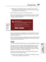
dardize on one type of NIC for use with all of its workstations. Figure 5-1 depicts a typical
PCI NIC.
A newer version of the PCI standard is PCI Express, which specifies a 64-bit bus with a 133-
MHz clock speed capable of transferring data at up to 500 MBps per data path, or lane, in
full-duplex transmission. PCI Express, which was introduced in 2002, follows a new type of
bus design and offers several advantages over the old PCI: more efficient data transfer, support
for quality of service distinctions, error reporting and handling, and compatibility with the
current PCI software. Also, PCI Express cards are designed to fit into PCs that currently have
older PCI slots. (This requires the addition of a small slot behind each of two existing PCI
slots. The PCI Express card is then inserted into both PCI slots.) PCI Express slots vary
depending on the number of lanes they support: An x1 slot supports a single lane, an x2 slot
supports two lanes, and so on. Each lane offers a full-duplex throughput of 500 Mbps. A PCI
Express slot can support up to 16 lanes, and an x16 slot can provide 8 Gbps throughput. Com-
puters such as servers that must perform fast data transfer are already using the PCI Express
standard, and manufacturers predict that PCI Express will replace PCI in most PCs in com-
ing years. PCI Express is sometimes referred to as PCIe or PCIx. Figure 5-2 depicts a PCI
Express x1 NIC.
You can easily determine the type of bus your PC uses by reading the documentation that
came with the computer. Someday, however, you may need to replace a NIC on a PC whose
documentation is missing. To verify the type of bus a PC uses, you can look inside the PC
case. (Later in this chapter, you will learn how to open a computer case, check the computer’s
bus, and install a NIC safely.) Most PCs have at least two different types of bus connections
on the same motherboard. Figure 5-3 illustrates a motherboard with ISA, PCI, and PCI
Express expansion slots.
If a motherboard supports more than one kind of expansion slot, refer to the NIC and PC man-
ufacturers’ guidelines (either in print or on the Web) for information on the preferred type of
NIC. If possible, you should choose a NIC that matches the most modern bus on the moth-
erboard. For example, if a PC supports both ISA and PCI, attempt to use a PCI NIC.
Although you may be able to use the older bus and NIC types without any adverse effects, some
NICs will not work in an older bus if a faster, newer bus is available on the motherboard.
196 Chapter 5
NETWORKING HARDWARE
NET+
1.6
Chapter 5 197
NICS (NETWORK INTERFACE CARDS)
FIGURE 5-1 PCI NIC FIGURE 5-2 PCI Express x1 NIC
FIGURE 5-3 A motherboard with multiple expansion slots
NET+
1.6
Peripheral Bus Standards
Some peripheral devices, such as modems or NICs, are attached to the computer’s bus exter-
nally rather than internally. PCMCIA (Personal Computer Memory Card International Asso-
ciation), USB (universal serial bus), CompactFlash, or FireWire (IEEE 1394) slots can all be
used to connect peripherals such as NICs. One advantage to externally attached NICs is their
simple installation. Typically, an externally attached adapter needs only to be plugged into the
port to be physically installed. An expansion board NIC, on the other hand, requires the user
to turn off the computer, remove its cover, insert the board into an expansion slot, fasten the
board in place, replace the cover, and turn on the computer. The oldest externally attached type
of NIC still in use today is the PCMCIA adapter.
In 1989, a group of PC system and computer manufacturers formed the Personal Computer
Memory Card International Association or PCMCIA. The group’s original goal was to
establish a standard method for connecting external memory to a portable computer. Later, see-
ing the potential for many other uses, PCMCIA revised the standard and offered cards that
could connect virtually any type of external device. Now PCMCIA slots may be used to con-
nect external modems, NICs (for either wire-bound or wireless networks), hard disks, or CD-
ROM drives to most laptop computers.
The first standard PCMCIA-standard adapter to be released, called PC Card, specified a 16-
bit interface running at 8 MHz. However, the PC Card standard was hampered by its slow
data transfer rates. In the 1990s, recognizing the need for a faster standard, the PCMCIA group
developed CardBus. CardBus specifies a 32-bit interface running at 33 MHz, which matches
the PCI expansion board standard. Most modern laptops are equipped with CardBus slots.
Figure 5-4 depicts a typical CardBus NIC.
As demand for more and faster data transfer grows, PCMCIA has continued to improve its
standards. Recently it released the ExpressCard standard. ExpressCard allows many different
external devices to connect to portable computers through a 26-pin interface, and offers data
transfer rates of 250 MBps in each direction (for a total of 500 MBps). It uses the same data
198 Chapter 5
NETWORKING HARDWARE
FIGURE 5-4 A CardBus NIC
NET+
1.6
transfer standards as those specified in the PCI Express specification. ExpressCard modules
come in two sizes: 34 mm (40% smaller than current CardBus modules) and 54 mm wide (the
same width as CardBus modules). The smaller sized module will grow more desirable as devices
grow thinner and lighter. This new size is also compatible with smaller devices such as PDAs,
Tablet PCs, and digital cameras. Over time, PCMCIA expects the ExpressCard standard to
replace the CardBus standard. Figure 5-5 shows examples of the two types of ExpressCard
modules.
Chapter 5 199
NICS (NETWORK INTERFACE CARDS)
FIGURE 5-5 Express Card modules
PCMCIA-standard adapters are often called “credit card adapters” because they are
approximately the same size as a credit card.
NOTE
Another type of externally attached NIC is one that relies on a USB (universal serial bus) port.
USB is a standard interface used to connect multiple types of peripherals, including modems,
mice, audio players, and NICs. The original USB standard was developed in 1995 by a group
of computer manufacturers working to make a low-cost, simple-to-install method of connect-
ing peripheral devices to any make or model of computer. Since 1998, USB ports have been
supplied on the motherboards of most modern laptop and desktop computers.
USB adapters may follow one of two USB standards: USB 1.1 or USB 2.0. The primary dif-
ference between the two standards is speed. The USB 1.1 standard has a maximum data trans-
fer rate of 12 Mbps. The 2.0 standard can reach 480 Mbps, if the correct transfer options are
NET+
1.6
NET+
1.4
1.6
selected and if the attached device is capable of supporting that speed. Most new PCs are
shipped with USB 2.0 ports. Figure 5-6 shows an example of a USB NIC, which has a USB
connector on one end and an RJ-45 receptacle on the other end.
200 Chapter 5
NETWORKING HARDWARE
FIGURE 5-6 A USB NIC
Yet another peripheral bus type is called FireWire. Apple Computer began developing the
FireWire standard in the 1980s, and it was codified by the IEEE as the IEEE 1394 standard
in 1995. It has been included on the motherboards of Macintosh computers for many years,
but has become common on PCs only in the last few years. As with PCMCIA and USB stan-
dards, FireWire has undergone several improvements since its inception. Traditional FireWire
connections support a maximum throughput of 400 Mbps. A newer version of the standard
supports potential throughput rates of over 3 Gbps.
FireWire can be used to connect most any type of peripheral, such as a digital camera, VCR,
external hard disk, or CD-ROM drive, to a desktop or laptop computer. It can also be used to
connect two or more computers on a small network using a bus topology—that is, by linking
one computer to another in a daisy-chain fashion. On such a network, FireWire supports a
maximum of 63 devices per segment, allows for up to 4.5 meters between nodes, and the chain
of FireWire-linked computers can extend no farther than 72 meters from end to end. If your
computer doesn’t come with a FireWire port, you can install a FireWire NIC, which is a card
(usually PCI or PCMCIA) that contains a FireWire port, to allow for this type of network.
FireWire-connected peripherals, such as USB- and PCMCIA-connected peripherals, are
simple to install and supported by most modern operating systems. Connectors come in two
varieties: 4-pin and 6-pin. The 6-pin connector contains two pins that can be used to supply
power to a peripheral. It is also the one most frequently used for interconnecting computers.
FireWire has distinctively small connectors and a thin cable, as shown in Figure 5-7.
A fourth external bus standard is the CompactFlash standard. The original group of 12 elec-
tronics companies that formed the CompactFlash Association (CFA) designed CompactFlash
as an ultra-small, removable data and input/output device that would connect to many kinds
of peripherals. If you have used a digital camera recently, chances are you’ve saved photos on a
NET+
1.4
1.6
NET+
1.6
CompactFlash storage card. However, CompactFlash slots can also be used to connect to a net-
work. The latest CompactFlash standard, 2.0, provides a data transfer rate of 16 MBps. Note
that this is significantly slower than any of the current external adapter standards discussed pre-
viously. Because of their relatively slower speed, CompactFlash NICs are most likely to be
found connecting devices too small to handle PCMCIA slots (for example, PDAs or comput-
ers embedded into other devices, such as defibrillators or heart monitors). They are often used
in wireless connections, although CompactFlash NICs with RJ-45 connectors do exist, as
shown in Figure 5-8.
Chapter 5 201
NICS (NETWORK INTERFACE CARDS)
FIGURE 5-7 FireWire connectors (4-pin and 6-pin)
FIGURE 5-8 A CompactFlash NIC
NET+
1.6
On-Board NICs
Not all peripheral devices are connected to a computer’s motherboard via an expansion slot or
peripheral bus. Some are connected directly to the motherboard using on-board ports.For
example, the electrical connection that controls a computer’s mouse operates through an on-
board port, as does the connection for its keyboard and monitor. Many new computers also use
on-board NICs, or NICs that are integrated into the motherboard. The advantage to using an
on-board NIC is that it saves space and frees expansion slots for additional peripherals. When
a computer contains an on-board network adapter, its RJ-45 port is usually located on the back
or, with some laptops, on the side of the computer.
Wireless NICs
NICs are designed for use with either wire-bound or wireless networks. As you have learned,
wireless NICs use an antenna (either internal or external) to exchange signals with a base sta-
tion transceiver or another wireless NIC. Wireless NICs can be found for all of the bus types
discussed in this chapter. One disadvantage to using wireless NICs is that currently they are
somewhat more expensive than wire-bound NICs. (Other reasons for choosing wire-bound
NICs over wireless, if the choices are equally convenient, are the bandwidth and security lim-
itations of wireless transmission. These limitations are discussed elsewhere in the book.) Figure 5-9
depicts wireless PCI, CardBus, and USB NICs.
202 Chapter 5
NETWORKING HARDWARE
FIGURE 5-9 Wireless NICs
NET+
1.6
Installing NICs
To install a NIC, you must first install the hardware, and then install the software that shipped
with it. In some cases, you may also have to perform a third step: configuring the firmware,a
set of data or instructions that has been saved to a read-only memory (ROM) chip (which is
on the NIC). The ROM’s data can be changed by a configuration utility program provided
with the NIC. Because its data can be erased or changed by applying electrical charges to the
chip (via the software program), this particular type of ROM is called EEPROM (electrically
erasable programmable read-only memory). You’ll learn more about a NIC’s firmware later
in the chapter. The following sections explain how to install and configure NICs.
Installing and Configuring NIC Hardware
It’s always advisable to start by reading the manufacturer’s documentation that accompanies the
NIC hardware. The following steps generally apply to any kind of expansion card NIC instal-
lation in a desktop computer, but your experience may vary.
To install an expansion card NIC:
1. Make sure that your toolkit includes a Phillips-head screwdriver, a ground strap, and a
ground mat to protect the internal components from electrostatic discharge. Also,
make sure that you have ample space in which to work, whether it be on the floor, a
desk, or table.
2. Turn off the computer’s power switch, and then unplug the computer. In addition to
endangering you, opening a PC while it’s turned on can damage the PC’s internal cir-
cuitry. Also unplug attached peripherals and the network cable, if necessary.
3. Attach the ground strap to your wrist and make sure that it’s connected to the ground
mat underneath the computer.
4. Open the computer’s case. Desktop computer cases are attached in several different
ways. They might use four or six Phillips-head screws to attach the housing to the
back panel, or they might not use any screws and slide off instead. Remove all neces-
sary screws and then remove the computer’s case.
5. Select a slot on the computer’s motherboard where you will insert the NIC. Make
sure that the slot matches the type of expansion card you have. Remove the metal slot
cover for that slot from the back of the PC. Some slot covers are attached with a sin-
gle Phillips-head screw; after removing the screw, you can lift out the slot cover.
Other slot covers are merely metal parts with perforated edges that you can punch or
twist out with your hands.
6. Insert the NIC by lining up its slot connector with the slot and pressing it firmly into
the slot. Don’t be afraid to press down hard, but make sure the expansion card is
properly aligned with the slot when you do so. If you have correctly inserted the NIC,
it should not wiggle near its base. (Depending on the card’s size and thickness, it may
have some inherent flexibility, however.) A loose NIC causes connectivity problems.
Figure 5-10 shows a closeup of a NIC firmly seated in its slot.
Chapter 5 203
NICS (NETWORK INTERFACE CARDS)
NET+
1.6
3.2
7. The metal bracket at the end of the NIC should now be positioned where the metal
slot cover was located before you removed the slot cover. Attach the bracket with a
Phillips-head screw to the back of the computer cover to secure the NIC in place.
8. Make sure that you have not loosened any cables or cards inside the PC or left any
screws or debris inside the computer.
9. Replace the cover on the computer and reinsert the screws that you removed in Step
4, if applicable. Also reinsert any cables you removed.
10. Plug in the computer and turn it on. Proceed to configure the NIC’s software, as dis-
cussed later in this chapter.
Physically installing a PCMCIA-standard NIC is much easier than installing an expansion
card NIC. In general, you can simply turn off the machine, insert the card into the PCMCIA
slot, as shown in Figure 5-11, then turn on the computer. Most modern operating systems (such
as Windows XP) allow you to insert and remove the PCMCIA-standard adapter without
restarting the machine. Make sure that the card is firmly inserted. If you can wiggle it, you need
to realign it or push it in farther. Installing other types of external NICs, such as USB, Express-
Card, and CompactFlash adapters, is similar. All you need to do is insert the device into the
computer’s port, making sure that it is securely attached.
204 Chapter 5
NETWORKING HARDWARE
FIGURE 5-10 A properly inserted NIC
NET+
1.6
3.2
On servers and other high-powered computers, you may need to install multiple NICs. For
the hardware installation, you can simply repeat the installation process for the first NIC,
choosing a different slot. The trick to using multiple NICs on one machine lies in correctly
configuring the software for each NIC. Simple NIC configuration is covered in the following
section. The precise steps involved in configuring NICs on servers will depend on the server’s
networking operating system.
On older expansion board NICs, rather than using firmware utilities to modify settings, you
may need to set a jumper or DIP switch. A jumper is a small, removable piece of plastic that
contains a metal receptacle. This metal receptacle fits over a pair of pins on a circuit board to
complete a circuit between those two pins. A DIP (dual inline package) switch is a small, plas-
tic toggle switch that can represent an “on” or “off ” status that indicates a parameter setting.
To set jumpers and DIP switches properly, refer to the documentation for the adapter (typi-
cally available at the manufacturer’s Web site), which shows how different jumper and DIP
switch settings indicate particular NIC configurations.
Installing and Configuring NIC Software
Even if your computer runs an operating system with plug-and-play technology such as Win-
dows XP or Red Hat Linux, you must ensure that the correct device driver is installed for the
NIC and that it is configured properly. A device driver (sometimes called, simply, a driver) is
software that enables an attached device to communicate with the computer’s operating sys-
tem. When you purchase a computer that already contains an attached peripheral (such as a
Chapter 5 205
NICS (NETWORK INTERFACE CARDS)
FIGURE 5-11 Installing a PCMCIA-standard NIC
NET+
1.6
3.2
sound card), the device drivers should already be installed. However, when you add hardware,
you must install the device drivers. Most operating systems come with a multitude of built-in
device drivers. In that case, after you physically install new hardware and reboot, the operating
system automatically recognizes the hardware and installs the device’s drivers. Each time a com-
puter boots up, the device drivers for all its connected peripherals are loaded into RAM so that
the computer can communicate with those devices at any time.
In other cases, the operating system might not contain appropriate device drivers for the hard-
ware you’ve added. This section describes how to install and configure NIC software on a Win-
dows XP operating system that does not already contain the correct device drivers. For other
operating systems with plug-and-play capability, the process will be similar. Regardless of which
operating system you use, you should first refer to the NIC’s documentation, because your sit-
uation may vary. Read the NIC documentation carefully before installing the relevant drivers,
and make sure you are installing the appropriate drivers. Installing a device driver designed for
Windows 95 on a Windows XP computer, for example, may cause problems.
To install NIC software from a Windows XP interface, you need access to the Windows XP
software (via either a Windows XP CD or hard disk) and the device drivers specific to the NIC.
These drivers are typically found on CD-ROMs, or in some cases, floppy disks.
If you do not have the CD-ROM or floppy disk that shipped with the NIC and the Windows
XP software does not supply device drivers for your NIC, you can probably download the NIC
software from the manufacturer’s Web site. If you choose this option, make sure that you get
the appropriate drivers for your operating system and NIC type. Also, make sure that the dri-
vers you download are the most current version (sometimes called “shipping drivers”) and not
beta-level (unsupported) drivers.
To install and configure NIC software:
1. Physically install the NIC, and then restart the computer. Log on to the computer as
a user with administrator privileges.
2. As long as you haven’t disabled the plug-and-play technology in the computer’s
CMOS settings, Windows XP should automatically detect the new hardware. Upon
detecting the NIC, it should also install the NIC’s driver. In many cases, you need not
install any other software or adjust the configuration for the NIC to operate properly.
3. There are certain situations in which you might want to change or update the device driver
that the operating system has chosen. To do this, click Start on the task bar, and then click
Control Panel. The Control Panel window opens.
4. If necessary, switch to Category View. Then click Performance and Maintenance.
The Performance and Maintenance window appears.
5. Click System. The System Properties dialog box opens.
6. Select the Hardware tab, and then click the Device Manager button. The Device
Manager window opens, displaying a list of installed devices.
7. Double-click the Network adapters icon. A list of installed NICs appears.
206 Chapter 5
NETWORKING HARDWARE
NET+
1.6
3.2