Part 4: Code of practice for design of composite slabs with profiled steel sheeting ppt
Bạn đang xem bản rút gọn của tài liệu. Xem và tải ngay bản đầy đủ của tài liệu tại đây (1.07 MB, 38 trang )
BRITISH STANDARD
BS 5950-4:
1994
Structural use of
steelwork in building —
Part 4: Code of practice for design of
composite slabs with profiled steel
sheeting
UDC 693.814:669.14.018.29-417.2:692.533.15
BS5950-4:1994
This British Standard, having
been prepared under the
directionof Technical
CommitteeB/525, was
publishedunder the authority
ofthe Standards Board and
comesinto effect on
15 January 1994
© BSI 12-1998
First published December 1982
Second edition January 1994
The following BSI references
relate to the work on this
standard:
Committee reference B/525/4
Draft for comment 86/16901 DC
ISBN 0 580 21808 2
Committees responsible for this
British Standard
The preparation of this British Standard was entrusted by Technical
Committee B/525, Building and civil engineering structures, to Subcommittee
B/525/4, upon which the following bodies were represented:
Association of Consulting Engineers
British Cement Association
British Constructional Steelwork Association Ltd.
British Masonry Society
Building Employers Confederation
Department of the Environment (Building Research Establishment)
Department of the Environment (Construction Directorate)
Department of Transport
Federation of Civil Engineering Contractors
Institution of Civil Engineers
Institution of Structural Engineers
National Council of Building Material Producers
Royal Institute of British Architects
Timber Research and Development Association
The following bodies were also represented in the drafting of the standard,
through subcommittees and panels:
British Industrial Fasteners Federation
British Steel Industry
Concrete Society
Department of the Environment (Specialist Services)
Society of Engineers Incorporated
Steel Construction Institute
Amendments issued since publication
Amd. No. Date Comments
BS5950-4:1994
© BSI 12-1998
i
Contents
Page
Committees responsible Inside front cover
Foreword iii
Section 1. General
1.0 Introduction 1
1.1 Scope 1
1.2 References 1
1.3 Definitions 1
1.4 Symbols 2
Section 2. Limit state design
2.1 General principles 3
2.2 Loading 3
2.3 Design methods 4
2.4 Ultimate limit states 5
2.5 Serviceability limit states 5
2.6 Durability 5
Section 3. Materials
3.1 Profiled steel sheets 6
3.2 Steel reinforcement 6
3.3 Concrete 6
3.4 Shear connectors 8
3.5 Sheet fixings 8
Section 4. Design: general recommendations
4.1 Form of construction 9
4.2 Design stages 10
4.3 Temporary supports 10
4.4 Provision of reinforcement 10
4.5 Cover to reinforcement 10
4.6 Methods of developing composite action 12
4.7 Minimum bearing requirements 13
4.8 Constructional details 13
Section 5. Design: profiled steel sheeting
5.1 General 15
5.2 Load carrying capacity 15
5.3 Deflection of profiled steel sheeting 15
Section 6. Design: composite slab
6.1 General 16
6.2 Strength 16
6.3 Moment capacity 16
6.4 Shear capacity 18
6.5 Vertical shear and punching shear 20
6.6 Deflection of the composite slab 20
6.7 Concentrated loads 22
6.8 Nominal reinforcement at intermediate supports 22
6.9 Transverse reinforcement 23
6.10 Shear connection 23
BS5950-4:1994
ii
© BSI 12-1998
Page
Section 7. Fire resistance
7.1 General 24
7.2 Minimum thickness of concrete 24
7.3 Determination of fire resistance 24
Section 8. Testing of composite slabs
8.1 General 25
8.2 Specific tests 26
8.3 Parametric tests 27
Figure 1 — Arrangement of construction loads 3
Figure 2 — Sheet and slab dimensions 7
Figure 3 — Typical composite slab 9
Figure 4 — Typical profiles 11
Figure 5 — Bearing requirements 12
Figure 6 — Modes of failure of a composite slab 17
Figure 7 — Stress blocks for moment capacity 18
Figure 8 — Shear spans 19
Figure 9 — Critical perimeter for shear 21
Figure 10 — Distribution of concentrated load 23
Figure 11 — Test details 25
Figure 12 — Shear-bond failure 28
Table 1 — Values of g
f
for ultimate limit states 4
Table 2 — Span-to-depth ratios 22
List of references Inside back cover
BS5950-4:1994
© BSI 12-1998
iii
Foreword
This Part of BS 5950 has been prepared under the direction of Technical
Committee B/525, Building and civil engineering structures. BS 5950 comprises
codes of practice which cover the design, construction and fire protection of steel
structures and specifications for materials, workmanship and erection.
It comprises the following Parts and Sections:
— Part 1: Code of practice for design in simple and continuous construction: hot
rolled sections;
— Part 2: Specification for materials, fabrication and erection: hot rolled
sections;
— Part 3: Design in composite construction;
— Section 3.1: Code of practice for design of simple and continuous composite
beams;
— Part 4: Code of practice for design of composite slabs with profiled steel
sheeting;
— Part 5: Code of practice for design of cold formed sections;
— Part 6
1)
: Code of practice for design of light gauge profiled sheeting;
— Part 7: Specification for materials and workmanship: cold formed sections;
— Part 8: Code of practice for fire resistant design;
— Part 9: Code of practice for stressed skin design.
This Part of BS 5950 gives recommendations for the design of composite slabs in
which profiled steel sheeting acts compositely with concrete or acts only as
permanent formwork.
This British Standard supersedes BS 5950-4:1982, which is withdrawn.
BS 5950-4:1982 was the first Part of BS 5950 to be issued. Most of the other Parts
have since been issued or are expected to be published shortly. In addition
BS8110 has superseded CP 110. It was therefore necessary to update the
cross-references in this document, add material related to composite beams and
align the values of the partial safety factors for loads with those now
recommended in BS5950-1. A number of minor amendments have also been
made as a result of experience in the use of the code.
The work on BS 5950-3 led to a survey of construction loads, which was also
relevant to the recommendations of this Part and enabled the partial safety
factors for these loads to be rationalized. In addition it had become apparent in
the drafting of BS 5950-3 that some adjustments to terminology (such as
“composite slab”) would be beneficial for clarity and some symbols needed
additional subscripts to maintain compatibility with both BS 5950-3 and
BS5950-1. This revised terminology led to the modified title of Part 4.
A few further improvements have been made. These include recommendations on
span-to-depth ratios and on end anchorage. The density of lightweight concrete
covered has also been aligned with that in BS 5950-3.1.
The clauses on the design of profiled sheets have been replaced by
cross-references to BS 5950-6
1)
, rather than updated to align with Part 6.
Theneed to adjust the clause numbers to allow for the various additions and
omissions, has provided the opportunity to restructure the document in a manner
compatible with that now used in the other Parts of BS 5950, with the type of
clause numbering system now used in the other Parts of BS 5950.
1)
In preparation.
BS5950-4:1994
iv
© BSI 12-1998
Apart from the above changes, the technical content of the standard is
unchanged.
It has been assumed in the drafting of this British Standard that the execution of
its provisions is entrusted to appropriately qualified and experienced people, and
that construction and supervision are carried out by capable and experienced
organizations.
A British Standard does not purport to include all the necessary provisions of a
contract. Users of British Standards are responsible for their correct application.
Compliance with a British Standard does not of itself confer immunity
from legal obligations.
Summary of pages
This document comprises a front cover, an inside front cover, pages i to iv,
pages 1 to 30, an inside back cover and a back cover.
This standard has been updated (see copyright date) and may have had
amendments incorporated. This will be indicated in the amendment table on
theinside front cover.
BS5950-4:1994
© BSI 12-1998
1
Section 1. General
1.0 Introduction
1.0.1 Aims of economical structural design
The aim of structural design of a composite slab is
toprovide, with due regard to economy, a slab
capable of fulfilling its intended function and
sustaining the specified loads for its intended life.
The design should facilitate construction, both of
theslab itself and of the structure of which it forms
part.
The composite slab should be sufficiently robust
andinsensitive to the effects of minor incidental
loads applied during service that the safety of
otherparts of the structure is not prejudiced.
Although the ultimate strength recommendations
within this standard are to be regarded as limiting
values, the purpose in design should be to reach
these limits at as many places as possible,
consistent with economy, in order to obtain the
optimum combination of material and construction
costs.
1.0.2 Overall stability
The designer responsible for the overall stability
ofthe structure should ensure compatibility of
structural design and detailing between all those
structural parts and components which are required
for overall stability, even when some or all of the
structural design and detailing of those parts and
components is carried out by another designer.
1.0.3 Accuracy of calculation
For the purpose of deciding whether a particular
recommendation is satisfied, the final value,
observed or calculated, expressing the result of a
test or analysis should be rounded off. The number
of significant places retained in the rounded off
value should be the same as in the value given in the
recommendation.
1.1 Scope
This Part of BS 5950 gives recommendations for
thedesign of composite slabs with profiled steel
sheeting. It covers slabs spanning only in the
direction of span of the profiled steel sheets.
This code applies to the design of composite slabs
inbuildings. It does not apply to highway or railway
bridges, for which reference should be made to
BS5400-5.
For the design of composite steel beams with a
composite slab as the concrete flange, reference
should be made to BS 5950-3.1.
Diaphragm action produced by the capacity of the
composite slab (or of the profiled steel sheets at the
construction stage) to resist distortion in its own
plane is not within the scope of this Part of BS 5950.
For the design of profiled steel sheeting as a
stressed skin diaphragm, reference should be made
to BS 5950-9.
1.2 References
1.2.1 Normative references
This Part of BS 5950 incorporates, by reference,
provisions from specific editions of other
publications. These normative references are cited
at the appropriate points in the text and the
publications are listed on the inside back cover.
Subsequent amendment to, or revisions of, any of
these publications apply to this Part of BS 5950 only
when incorporated in it by amendment or revision.
1.2.2 Informative references
This Part of BS 5950 refers to other publications
that provide information or guidance. Editions of
these publications current at the time of issue of this
standard are listed on the inside back cover, but
reference should be made to the latest editions.
1.3 Definitions
For the purposes of this Part of BS 5950, the
following definitions apply.
1.3.1
composite slab
a slab consisting of profiled steel sheets and a
concrete slab, with steel reinforcement where
necessary
1.3.2
composite action
the structural interaction which occurs when the
components of a composite slab interact to form a
single structural element
1.3.3
permanent shuttering
profiled steel sheeting designed to support wet
concrete, reinforcement and construction loads
1.3.4
negative moment
bending moment causing compression at the bottom
of the slab
1.3.5
positive moment
bending moment causing tension at the bottom of
the slab
1.3.6
longitudinal reinforcement
reinforcement of a composite slab, running parallel
to the corrugations of the profiled steel sheets
BS5950-4:1994
2
© BSI 12-1998
Section 1
1.3.7
transverse reinforcement
reinforcement of a composite slab, running
perpendicular to the corrugations of the profiled
steel sheets
1.4 Symbols
a Distance from a concentrated load to the
nearer support
A
p
Cross-sectional area of profiled steel
sheeting
B
s
Width of composite slab
b
a
Mean width of trough (open sheet profile)
b
b
Minimum width of trough (sheet profile)
b
eb
Effective width of slab (bending)
b
er
Effective width of slab (shear)
b
m
Effective load width
b
o
Width of concentrated load
D
p
Overall depth of profiled steel sheets
D
s
Overall depth of composite slab
d
s
Effective depth of slab to centroid of
profiled steel sheets
E Modulus of elasticity of profiled steel sheets
F
a
End anchorage force per shear connector
F
b
Beam longitudinal shear force per shear
connector
f
cm
Concrete cube strength (observed value)
f
cu
Characteristic concrete cube strength
h
agg
Nominal maximum size of aggregate
I
CA
Second moment of area of the composite
slab about its centroidal axis (in equivalent
steel units)
k
r
Empirical parameter (intercept of reduction
line from parametric tests)
L
p
Effective span of profiled steel sheets,
which is the smaller of:
a) distance between centres of permanent
or temporary supports, and
b) clear span between permanent or
temporary supports plus overall depth of
profiled sheets D
p
L
s
Effective span of composite slab, which is
the smaller of:
a) distance between centres of permanent
supports, and
b) clear span between permanent supports
plus effective depth of composite slab d
s
L
v
Shear span of composite slab
N Number of shear connectors attached to the
end of each span of sheets, per unit length
of supporting beam
m
r
Empirical parameter (slope of reduction
line from parametric tests)
P
a
End anchorage capacity per shear
connector
P
b
Capacity per shear connector for composite
beam design
p
yp
Design strength of profiled steel sheets
Q
k
Characteristic resistance per shear
connector
R
e.min
Specified yield strength of profiled steel
sheets
t
f
Thickness of finishes above concrete slab
u Critical perimeter for punching shear
Shear capacity per unit width of composite
slab due to the end anchorage provided by
the shear connectors
Total longitudinal shear capacity per unit
width of composite slab
V
E
Maximum experimental shear force
V
P
Punching shear capacity of composite slab
V
s
Shear-bond capacity of composite slab
Shear-bond capacity of composite slab per
unit width
V
v
Vertical shear capacity of composite slab
v
c
Design concrete shear stress
W
c
Applied load capacity of composite slab
W
f
Reaction or concentrated load
W
ser
Serviceability load
W
st
Failure load
W
w
Anticipated value of the applied load
x
c
Depth of concrete in compression at
midspan
z Lever arm
g
f
Partial safety factor for loads
gm Partial safety factor for resistances
d Deflection
V
a
V
c
V
s
BS5950-4:1994
© BSI 12-1998
3
Section 2
Section 2. Limit state design
2.1 General principles
Composite slabs should be designed by considering
the limit states at which they would become unfit
fortheir intended use. Appropriate safety factors
should be applied for the ultimate limit state and
the serviceability limit state.
All limit states covered in BS 5950-1:1990 or in
BS8110-1:1985 should be considered.
The recommendations given in this Part of BS 5950
should be followed for the ultimate limit states of
strength and stability and for the serviceability
limit state of deflection.
2.2 Loading
2.2.1 General
All relevant loads should be considered separately
and in such realistic combinations as to cause the
most critical effects on the components and on the
composite slab as a whole.
Loading conditions during construction should also
be considered (see 2.2.3).
2.2.2 Dead, imposed and wind loading
Reference should be made to BS 6399-1:1984,
BS6399-3:1988 and CP 3:Chapter V-2:1972 for the
determination of the dead, imposed and wind loads.
The weight of the finished slab should be increased
if necessary to allow for the additional concrete
placed as a result of the deflection of the profiled
steel sheeting (see 5.3).
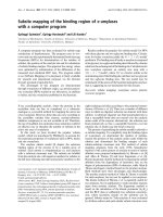
Figure 1 — Arrangement of construction loads
BS5950-4:1994
4
© BSI 12-1998
Section 2
2.2.3 Construction loads
2.2.3.1 Basic construction loads
Construction loads should be considered in addition
to the weight of the wet concrete slab.
In general purpose working areas the basic
construction load on one span of the sheeting should
be taken as not less than 1.5 kN/m
2
. The other spans
should be taken as either loaded with the weight
ofthe wet concrete slab plus a construction load of
one-third of the basic construction load, or unloaded
apart from the self-weight of the profiled steel
sheets, whichever is the more critical for the
positiveand negative moments in the sheeting
(seeFigure 1).
For spans of less than 3 m, the basic construction
load should be increased to not less
than 4.5/L
p
kN/m
2
, where L
p
is the effective span of
the profiled steel sheets in metres.
Allowance is made within these values for
construction operatives, impact and heaping of
concrete during placing, hand tools, small items of
equipment and materials for immediate use. The
minimum values quoted are intended for use in
general purpose working areas, but will not
necessarily be sufficient for excessive impact or
heaping of concrete, or pipeline or pumping loads.
Where excessive loads are expected, reference
should be made to BS 5975:1982.
Reference should also be made to 5.3 for possible
increased loading due to ponding at the construction
stage.
2.2.3.2 Storage loads
Where materials to be stored temporarily on erected
sheeting (or on a recently formed slab before it is
self-supporting) produce equivalent distributed
loads in excess of the basic construction loads,
provision should be made in the design for the
additional temporary storage loads.
2.2.4 Accidental loads
Accidental loads should be treated as recommended
in BS 5950-1.
2.3 Design methods
2.3.1 General
The following methods may be used for the design of
composite slabs:
a) composite design in which the concrete and the
profiled steel sheets are assumed to combine
structurally to support loads (see section 6);
b) design as a reinforced concrete slab as
recommended in BS 8110-1:1985, neglecting any
contribution from the profiled steel sheets;
c) design by specific testing (see 2.3.2.1).
In all cases the profiled steel sheeting should be
designed for use as permanent shuttering during
construction (see section 5).
Table 1 — Values of g
f
for ultimate limit states
Combination Type of load g
f
Dead and imposed load Dead load (see note) Maximum
Minimum
1.4
1.0
Imposed load 1.6
Dead and wind load Dead load (see note) Maximum
Minimum
1.4
1.0
Imposed load 1.4
Dead, imposed and wind load Dead load (see note) Maximum
Minimum
1.2
1.0
Imposed load
Wind load
1.2
1.2
Construction stage
(temporaryerection condition)
Dead load of wet concrete (see note) Maximum
Minimum
1.4
0.0
Construction loads (see 2.2.3) 1.6
NOTEFor dead loads, the minimum g
f
factor should be used for dead loads that counteract the effects of other loads causing
overturning or uplift.
BS5950-4:1994
© BSI 12-1998
5
Section 2
2.3.2 Testing
2.3.2.1 Specific tests
Where testing is used as an alternative to
calculation methods of design, the load carrying
capacity of a composite slab may be determined
directly from the results of specific tests as
recommended in 8.2.
2.3.2.2 Parametric tests
In the calculation method for composite design
given in section 6, the shear-bond capacity should
bedetermined using the empirical parameters
obtained from the results of parametric tests as
recommended in 8.3.
2.4 Ultimate limit states
2.4.1 Limit state of strength
In checking the strength of a composite slab, the
loads should be multiplied by the appropriate value
of the partial safety factor for loads g
f
given in
Table 1. The factored loads should be applied in the
most unfavourable realistic combination for the part
or effect under consideration.
2.4.2 Stability against overturning
The factored loads, considered separately and in
combination, should not cause the composite slab
(orthe profiled steel sheeting at the construction
stage) to overturn, slip or lift off its seating. The
combination of dead, imposed (or construction) and
wind loads should be such as to have the most
severe effect.
2.4.3 Strength of materials
In the design of the profiled steel sheeting before
composite action with the concrete slab is developed,
the design strength of the profiled steel sheets
should be taken as specified in BS 5950-6
2)
.
For the design of the composite slab, the design
strength p
yp
of the profiled steel sheets should be
taken as 0.93 times the specified yield strength
R
e.min
(see 3.1.1), or 0.93 times the characteristic
strength for the grade of steel used.
NOTE The value 0.93 represents 1/g
m
, where g
m
is a partial
safety factor allowing for tolerances.
The modulus of elasticity E of profiled steel sheets
should be taken as 210 kN/mm
2
.
The properties of concrete and reinforcement to be
used in design should follow the recommendations
of BS 8110.
2.5 Serviceability limit states
2.5.1 Serviceability loads
Generally, the serviceability loads should be taken
as the unfactored values (i.e. g
f
= 1.0). When
considering dead load plus imposed load plus wind
load, only 80% of the imposed load and wind load
need be considered.
Construction loads should not be included in the
serviceability loads.
2.5.2 Deflections
Deflections under serviceability loads should not
impair the strength or efficiency of the structure or
cause damage to the finishings.
The recommendations given in 5.3 should be
followed for profiled steel sheeting at the
construction stage and those given in 6.6 should
befollowed for the deflection of the composite slab.
2.6 Durability
2.6.1 Corrosion protection of profiled steel
sheets
The exposed surface at the underside of the profiled
steel sheets should be adequately protected to resist
the relevant environmental conditions, including
those arising during site storage and erection.
Reference should be made to BS 5493:1977 for the
recommended protective systems. Any damage to
zinc coating or other surface protection should be
made good.
NOTE 1Due to the possibility of corrosion caused by road
de-icing salts or sea salt, composite slabs with zinc coated profiled
steel sheeting may not be appropriate for use without special
measures in car park structures, or in the vicinity of seawater or
seawater spray.
NOTE 2Dilute acids from process industries (which are
sometimes airborne) may corrode galvanized surfaces.
2.6.2 Concrete durability
For the durability of the concrete in the composite
slab, the relevant recommendations in BS 8110
should be followed.
2.6.3 Fire resistance
The recommendations in section 7 should be
followed.
2)
In preparation.
BS5950-4:1994
6
© BSI 12-1998
Section 3
Section 3. Materials
3.1 Profiled steel sheets
3.1.1 Specification
The steel used to manufacture the profiled steel
sheets should have a specified yield strength R
e.min
of not less than 220 N/mm
2
and should generally
bein accordance either with BS 2989:1992 or with
BSEN 10147:1992. Steels conforming to other
specifications may alternatively be used provided
that they have similar properties.
3.1.2 Sheet thickness
The structural thickness of the profiled steel sheets,
to which the stresses and section properties apply,
should be taken as the “bare metal thickness” of the
sheets excluding any protective or decorative finish
such as zinc coating or organic coating.
The nominal bare metal thickness of the sheets
should not normally be less than 0.75 mm except
where the profiled steel sheets are used only as
permanent shuttering (see 4.1). Thinner sheets
should not be used unless adequate theoretical
evidence and test data are available to justify their
use.
3.1.3 Zinc coating
The zinc coating should conform to the
requirements of BS 2989:1992 or BS EN 10147:1992
as appropriate. A coating of 275 g/m
2
total,
including both sides (coating type G 275 in
accordance with BS 2989) is normally specified for
internal floors in a non-aggressive environment, but
the specification may be varied depending on service
conditions.
NOTE A 275 g/m
2
coating adds approximately 0.04 mm to the
bare metal thickness, 0.02 mm on each side. The nominal bare
metal thickness is thus 0.04 mm less than the nominal thickness
of the sheet.
Before a zinc coating heavier than 275 g/m
2
is
specified, confirmation should be obtained from
theproposed manufacturer of the profiled steel
sheets that the proposed coating thickness is
compatible with the forming operations involved.
All zinc coatings should be chemically passivated
with a chromate treatment to minimize wet storage
stains (white rusting) and reduce chemical reaction
at the concrete/zinc interface.
3.2 Steel reinforcement
3.2.1 Specification
The type of reinforcement used should satisfy the
recommendations of BS 8110 and should conform
toBS 4449:1988, BS 4482:1985 or BS 4483:1985,
subject to the recommendations in 3.2.2.
3.2.2 Ductility of reinforcement
Wherever account is taken in design of the efficiency
of continuity over a support, to ensure that the
reinforcement has adequate ductility the steel fabric
or reinforcing bars used as support reinforcement
should satisfy the minimum elongation requirement
specified in 10.1.2 of BS 4449:1988.
This recommendation should be applied to the
following:
a) reinforcement used to resist negative moments
in continuous spans or cantilevers;
b) distribution steel for concentrated loads or
around openings in the slab;
c) reinforcement used to increase the fire
resistance of the composite slab.
However it need not be applied to the following:
1) secondary transverse reinforcement;
2) nominal continuity reinforcement over
supports;
3) tensile reinforcement in the span.
3.3 Concrete
3.3.1 General
Concrete should follow the recommendations given
in BS 8110.
3.3.2 Lightweight concrete
The dry density of lightweight aggregate
structuralconcrete should normally be not less
than1 750 kg/m
3
.
Other densities can be used, but all references
tolightweight concrete elsewhere in this Part
ofBS5950 assume a dry density of at
least 1750 kg/m
3
. Where lightweight concrete of
less than 1750 kg/m
3
dry density is used, due
allowance should be made for variations in
properties of concrete and their effect on the
resistances of shear connectors.
3.3.3 Density
In the absence of more precise information, the
nominal density should be taken as follows.
a) For design of the profiled steel sheeting
(wetdensity):
2400 kg/m
3
for normal weight concrete;
1900 kg/m
3
for lightweight concrete.
b) For design of the composite slab (dry density):
2350 kg/m
3
for normal weight concrete;
1800 kg/m
3
for lightweight concrete.
NOTEFor lightweight concrete the density may be found in
manufacturers’ literature.
BS5950-4:1994
© BSI 12-1998
7
Section 3
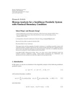
3.3.4 Aggregate size
The nominal maximum size of the aggregate h
agg
depends on the smallest dimension in the structural
element within which concrete is poured and should
be not greater than the least of:
a) 0.4 (D
s
– D
p
) (see Figure 2);
b) b
b
/3 (see Figure 2);
c) 20 mm.
3.3.5 Slab thickness
The overall depth of the composite slab D
s
should be
sufficient to provide the required resistance to the
effects of fire (see 7.2) and as a minimum should
notbe less than 90 mm. The thickness of concrete
(D
s
– D
p
) above the main flat surface of the top of the
ribs of the profiled steel sheets should be not less
than 50 mm subject to cover of not less than 15 mm
above the top of any shear connectors.
Figure 2 — Sheet and slab dimensions
BS5950-4:1994
8
© BSI 12-1998
Section 3
3.3.6 Admixtures
Admixtures may be used following the
recommendations of BS 8110, provided that the
zinccoating of the profiled sheets is not adversely
affected. The profiled steel sheets should be
considered as “embedded metal” when applying the
recommendations of BS 8110.
3.4 Shear connectors
3.4.1 General
Shear connectors should satisfy the
recommendations of BS 5950-3.1:1990. Resistances
of shear connectors other than those given in
BS5950-3.1:1990 should be determined on the basis
of push-out tests.
3.4.2 Stud shear connectors
The influence of the density of concrete on the
design value of stud shear connectors should be
allowed for. The characteristic resistances of stud
shear connectors in lightweight aggregate concrete
of dry density not less than 1750 kg/m
3
should be
taken as 90% of the values in normal weight
concrete, as recommended in BS 5950-3.1:1990.
3.5 Sheet fixings
Screws and other mechanical fasteners used to fix
the profiled steel sheets to the beams or other
supports, and fasteners used at side laps of sheets,
should be in accordance with BS 5950-6
3)
.
3)
In preparation.
BS5950-4:1994
© BSI 12-1998
9
Section 4
Section 4. Design: general recommendations
4.1 Form of construction
Composite slabs (see Figure 3), should consist of
in-situ concrete placed on profiled steel sheets,
designed to act as permanent shuttering for the
wetconcrete, so that as the concrete hardens it will
combine structurally with the profiled steel sheets
to form a composite element.
Composite action should be obtained in one of the
following ways:
a) by mechanical interlock;
b) by friction induced by the profile shape;
c) by end anchorages;
d) by a combination of c) with either a) or b).
Any bonding or adhesion of a chemical nature
should be neglected in design.
Steel reinforcement should be provided where
necessary (see 4.4). However, steel reinforcement
should not be used to resist positive moments in
combination with profiled steel sheets, unless the
moment capacity has been determined by testing
(see 6.3).
Alternatively the profiled steel sheeting should be
designed to act only as permanent shuttering. In
this case tensile reinforcement should be provided
in the span and the slab should be designed as
reinforced concrete as recommended in BS 8110,
without relying on composite action with the
profiled sheets.
NOTE 1In practice, this alternative type of slab often provides
some degree of composite action, and it is difficult to prevent it
from doing so. The action so produced does not prejudice its
structural efficiency, because removal of the steel shuttering
(ifthis could be done without any damage to the concrete) would
not significantly reduce the strength of the slab or its fire
resistance. The profiled steel sheets are left in place, but any
beneficial effect they may have is neglected in design.
Where service ducts are formed in the slab, due
allowance should be made for the resulting
reduction in load carrying capacity (see 6.1.3).
NOTE 2The reduction in load carrying capacity is particularly
severe in the case of ducts running transverse to the span of the
slab.
Figure 3 — Typical composite slab
BS5950-4:1994
10
© BSI 12-1998
Section 4
4.2 Design stages
The following stages should be considered in the
design of composite slabs.
a) Stage 1. Profiled steel sheeting as formwork.
The assessment of commercially available shapes
of profiled steel sheets, used as formwork to
support wet concrete. This includes checking the
load carrying capacity, the deflection and the
effects of using props (see section 5).
b) Stage 2. Composite slab. Composite action
between the profiled steel sheets and the
structural concrete slab. This includes checking
the load carrying capacity and the deflection
(see section 6).
4.3 Temporary supports
Normally unpropped construction should be used.
However, where safe span limits for construction
would otherwise be exceeded, temporary supports
should be provided to the profiled steel sheeting
until the concrete has reached an adequate
strength, in order to avoid exceeding the capacity
ofthe profiled steel sheets under the loading of wet
concrete and construction loads. Propped
construction should also be used to reduce the
deflection of the profiled steel sheeting, where the
deflection limits would otherwise be exceeded.
Where temporary supports are used, the effects of
their use and subsequent removal on the
distribution of shear forces in the composite slab
should be allowed for in the design of both the
supporting and the supported slabs.
NOTEIt is essential that temporary supports should be used
only where specified in the design documents or drawings.
The method of providing temporary supports should
be chosen to suit the conditions on site. Normally,
one of the following should be used:
a) temporary props from beneath;
b) temporary beams at the soffit of the sheets.
Alternative methods may be used where suitable
but, in all cases, the temporary support should be
capable of carrying all the loads and forces imposed
on it without undue deflection.
Where isolated temporary supports are used, a
spreader beam should be incorporated in order to
provide a continuous support to the profiled steel
sheets. Unless otherwise specified in the design
documents or drawings, this should be parallel to
the permanent supports.
Regardless of the method of support used, the
arrangement should be such that the soffit of the
sheet is not cambered above a line joining the level
of the permanent supports by a distance greater
than L
s
/350, where L
s
is the effective span of the
composite slab.
Any slab used to support temporary props should be
checked for adequate resistance to the forces applied
by the props, or during the removal of the props,
using the appropriate concrete strength for the age
of that slab.
4.4 Provision of reinforcement
Steel reinforcement, in the form of either bars or
steel mesh fabric, should be provided in composite
slabs as follows:
a) nominal continuity reinforcement over
intermediate supports, for simple spans;
b) full continuity reinforcement over
intermediate supports, for continuous spans and
for cantilevers;
c) distribution steel, where concentrated loads
are applied and around openings;
d) secondary transverse reinforcement to resist
shrinkage and temperature stresses.
Where necessary, steel reinforcement should also be
provided as follows:
1) to increase the fire resistance of the composite
slab;
2) as tensile reinforcement in the span.
4.5 Cover to reinforcement
Steel reinforcement in a slab in the form of bars or
steel mesh fabric should be positioned as follows.
a) Longitudinal reinforcement in the bottom of
the slab should be so positioned that sufficient
space, not less than the nominal maximum size of
the aggregate, is left between the reinforcement
and the sheets to ensure proper compaction of the
concrete.
b) Transverse reinforcement in the bottom of the
slab should be placed directly on the top of the
ribs of the sheets.
c) Distribution steel in areas of concentrated
loads and around openings should be placed
directly on the top of the ribs of the sheets, or
notmore than a nominal 25 mm above it.
d) Fire resistance reinforcement intended to
provide positive moment capacity should be
placed in the bottom of the slab with not less
than25 mm between the reinforcement and the
bottom of the sheets.
BS5950-4:1994
© BSI 12-1998
11
Section 4
e) Reinforcement in the top of the slab should
have 25 mm
4)
nominal cover.
f) Fire resistance reinforcement for negative
moment capacity should be placed in the top
ofthe slab with 25 mm
4)
nominal cover.
g) Secondary transverse reinforcement for
controlling shrinkage should be placed in the top
of the slab with 25 mm
4)
nominal cover.
The curtailment and lapping of reinforcement
should conform to BS 8110. Where a single layer of
reinforcement is used to fulfil more than one of the
above purposes, it should satisfy all the relevant
recommendations.
NOTELongitudinal and transverse are used here as defined
in1.3 to describe slab reinforcement. Where a composite slab
forms the concrete flange of a composite beam, BS 5950-3.1 gives
recommendations for transverse reinforcement of the beam,
running perpendicular to the span of the beam. Such
reinforcement can be either longitudinal or transverse relative to
the slab.
4)
The nominal cover of 25 mm is common practice, but in appropriate cases this may be reduced to values in accordance with
Tables 3.4 and 3.5 of BS 8110-1:1985 or Tables 5.1 and 5.2 of BS 8110-2:1985.
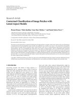
Figure 4 — Typical profiles
BS5950-4:1994
12
© BSI 12-1998
Section 4
4.6 Methods of developing composite
action
4.6.1 General
The shear connection needed for composite action
should be developed either by shear bond between
the concrete and the profiled steel sheets or else by
end anchorage, or by a combination of both methods
(see 4.6.6).
For shear bond, the profiled steel sheets should be
capable of transmitting horizontal shear at the
interface between the sheet and the concrete. This
should be achieved by one or more of the methods
given in 4.6.3 to 4.6.5 or by any other proven
method. In all cases the shear-bond capacity should
be determined by testing (see section 8).
4.6.2 Plain open profiled sheets
Plain open profiled sheets should not be used where
composite action is required, unless accompanied
bysome means of shear connection (see 4.6.5
and4.6.6).
4.6.3 Plain re-entrant angle profiled sheets
Plain re-entrant angle profiled sheets, as illustrated
in Figure 4a), should be designed to provide shear
connection between the sheets and the concrete by
means of the interlocking effect of the re-entrant
shape.
Figure 5 — Bearing requirements
BS5950-4:1994
© BSI 12-1998
13
Section 4
4.6.4 Embossed profiled sheets
Embossed profiled sheets, as illustrated in
Figure 4b), Figure 4c) and Figure 4d), should be
designed to develop shear connection through
embossments (or embossments and indentations)
inthe webs and/or flanges of the sheets.
4.6.5 Small holes in profiled sheets
Holes in the webs and/or flanges of profiled steel
sheets, intended to develop shear connection, should
be sufficiently large for concrete to fill the hole,
butsufficiently small to minimize the loss of fine
material from the concrete, unless a permanent
backing tape is provided on the underside which
prevents this loss.
4.6.6 End anchorage
Shear connectors may be used as end anchorages
toproduce composite action in slabs which are
designed as simply supported. Where sheets are
notcontinuous over a support, end anchors should
be provided at the ends of both sheets.
Where the end anchorage provided by shear
connectors is used in conjunction with the shear
bond between the concrete and the profiled steel
sheets, account should be taken of the influence of
the deformation capacity of the shear connectors on
the shear bond between the concrete and the sheets,
as recommended in 6.4.3.
The necessary interaction between stud shear
connectors and the profiled steel sheets should
normally be achieved by welding them to the
structural steelwork by the site technique of
through-the-sheet welding. Shear connectors
directly attached to the structural steelwork prior
toplacing the profiled steel sheets should not be
used as end anchorages unless the sheets are also
attached to the steelwork as recommended in 4.8.1,
by means of fixings of sufficient capacity.
NOTE If studs are welded to the beams prior to placing the
profiled steel sheets, it may be found necessary to use single span
sheets, in which case stop ends (see 4.8.4.3) may be needed to
prevent concrete loss.
Where end anchorage is provided by types of shear
connectors which connect the concrete slab directly
to the profiled steel sheets, such as self-drilling
self-tapping screws with enlarged washers, account
should be taken of the deformation capacity of such
shear connectors on the interaction between the
slab and the sheets.
Where shear connectors used as end anchorages
areassumed in design to act also as shear
connectors in composite beams, reference should
bemade to6.10.1.
Where composite slabs are used in conjunction with
reinforced concrete beams (see 6.10.2), any end
anchorage required should normally be achieved by
means of reinforcing bars.
4.6.7 Sheet edges
For profiles such as that shown in Figure 4e), the
edges of adjacent sheets should be overlapped or
crimped in such a way as to provide an effective
horizontal shear transfer between the sheets.
4.7 Minimum bearing requirements
In all cases the bearing length of a composite slab
should be sufficient to satisfy the recommendations
of 5.2 for load carrying capacity as permanent
formwork and the recommendations of BS 8110 for
load carrying capacity as a composite slab.
Composite slabs bearing on steel or concrete
shouldnormally have an end bearing of not less
than 50mm [see Figure 5a) and Figure 5c)]. For
composite slabs bearing on other materials, the
endbearing should normally be not less than 70 mm
[see Figure 5b) andFigure 5d)].
For continuous slabs the minimum bearing at
intermediate supports should normally be 75 mm
onsteel or concrete and 100 mm on other materials
[seeFigure 5e) and Figure 5f)].
Where smaller bearing lengths are adopted, account
should be taken of all relevant factors such as
tolerances, loading, span, height of support and
provision of continuity reinforcement. In such cases,
precautions should also be taken to ensure that
fixings (see 4.8.1) can still be achieved without
damage to the bearings, and that collapse cannot
occur as a result of accidental displacement during
erection.
4.8 Constructional details
4.8.1 Sheet fixings
The design should incorporate provision for the
profiled steel sheets to be fixed:
a) to keep them in position during construction so
as to provide a subsequent safe working platform;
b) to ensure connection between the sheets and
supporting beams;
c) to ensure connection between adjacent sheets
where necessary;
d) to transmit horizontal forces where necessary;
e) to prevent uplift forces displacing the sheets.
BS5950-4:1994
14
© BSI 12-1998
Section 4
For fixing sheets to steelwork, the following types of
fixing are available:
— shot fired fixings;
— self-tapping screws;
— welding;
— stud shear connectors welded through the
sheeting;
— bolting.
Due consideration should be given to any adverse
effect on the supporting members.
Site welding of very thin sheets should not be
reliedon to transfer end anchorage forces, unless
the practicality and quality of the welded
connections can be demonstrated by tests.
When sheets are to be attached to brickwork,
blockwork, concrete or other materials where there
is a danger of splitting, fixing should be by drilling
and plugging or by the use of suitable proprietary
fixings.
The number of fasteners should be not less than two
per sheet at the ends of sheets nor less than one per
sheet where the sheets are continuous. The spacing
of fasteners should be not greater than 500 mm at
the ends of sheets nor greater than 1000 mm where
the sheets are continuous. At side laps the sheets
should be fastened to each other, as necessary, to
control differential deflection, except where the
sides of the sheets are supported or are sufficiently
interlocking.
The design of all sheet fixings should be in
accordance with BS 5950-6
5)
.
4.8.2 Cantilever edges
The design should include provisions for adequate
support of profiled steel sheets during construction
at all cantilever edges and the like, including
unsupported edges occurring at cut-outs or openings
for columns.
4.8.3 Openings
4.8.3.1 Permanent openings
Reinforcement should be provided around
permanent openings to avoid cracking of the
composite slab.
4.8.3.2 Temporary openings
Where sheets are required to be temporarily left
out(or cut out) during construction, due allowance
should be made for the resulting loss of continuity
inthe design of the profiled steel sheeting
(seesection 5). Where necessary, thicker sheets
ortemporary supports should be used at such
locations.
4.8.4 Slab construction
4.8.4.1 Preparation
All extraneous grease, oil, dirt and deleterious
matter should be removed from the upper surface
ofthe sheets, but any greasiness remaining on the
sheets from the forming process need not be
removed.
4.8.4.2 Construction joints
Construction joints in composite slabs should be
positioned close to the supporting beams.
4.8.4.3 Stop ends
Stop ends should be provided where necessary to
prevent loss of grout at supports at which the
sheeting is discontinuous.
4.8.5 Waterproofing
Where composite slabs are used for roofs, or other
locations with impervious surface membranes, the
design should incorporate provision for the free
passage of water vapour.
5)
In preparation.
BS5950-4:1994
© BSI 12-1998
15
Section 5
Section 5. Design: profiled steel sheeting
5.1 General
The design of profiled steel sheeting supporting
loads before composite action is developed should
follow the recommendations given in this section.
The recommendations given in BS 5950-6
6)
should
be followed for the calculation of cross-sectional
properties. Alternatively the load-carrying capacity
of the profiled steel sheeting should be determined
by testing (see 5.2).
Embossments and indentations designed to
providecomposite action should be ignored when
calculating the cross-sectional properties of the steel
sheets.
NOTEThe cross-sectional properties of commercially available
profiles can be found in manufacturers’ literature, together with
information on effective cross-sectional properties at various
stress levels.
5.2 Load carrying capacity
For design purposes, the loads carried by the
profiled steel sheeting should be the dead load of
thesheets, wet concrete and reinforcement, the
construction loads (see 2.2.3), the effects of any
temporary propping used at this stage and, where
necessary, wind forces.
For simple spans, the capacity of the profiled steel
sheeting should be determined as recommended in
BS 5950-6
6)
by either:
a) calculation; or
b) testing.
For sheets continuous over more than one span, the
capacity should be determined either by using one of
the methods recommended for simple spans or from
a hybrid design method, based on elastic section
properties supplemented by information obtained
by testing.
NOTEAn appropriate hybrid design method is given in CIRIA
Technical Note 116[1].
5.3 Deflection of profiled steel
sheeting
The deflections of profiled steel sheeting should be
calculated as recommended in BS 5950-6
6)
using the
serviceability loads (see 2.5.1) for the construction
stage, comprising the weight of the profiled sheets
and the wet concrete only. These deflections should
not normally exceed the following:
a) L
p
/180 (but # 20 mm) when the effects of
ponding are not taken into account;
b) L
p
/130 (but # 30mm) when the effects of
ponding are taken into account, i.e. the weight
ofadditional concrete due to the deflection of the
sheeting is included in the deflection calculation;
where L
p
is the effective span of the profiled steel
sheets.
These limits should be increased only where it can
be shown that greater deflections will not impair the
strength or efficiency of the slab.
These limits should be reduced, if necessary, where
soffit deflection is considered important, e.g. for
service requirements or aesthetics.
When the deflection [calculated as in item a]
exceeds D
s
/10, where D
s
is the overall depth of the
composite slab, the additional weight of concrete
due to the deflection of the sheeting should be taken
into account in the self-weight of the composite slab,
for use in section 6 and in the design of the
supporting structure.
6)
In preparation.
BS5950-4:1994
16
© BSI 12-1998
Section 6
Section 6. Design: composite slab
6.1 General
6.1.1 Continuity
Composite slabs should be designed as either:
a) simply supported, with nominal reinforcement
over intermediate supports in accordance
with6.8; or
b) continuous, with full continuity reinforcement
over intermediate supports in accordance with
BS8110.
NOTEGenerally, composite slabs are designed as simply
supported, with nominal steel mesh reinforcement over supports.
6.1.2 Continuous slabs
For multiple spans designed as a continuous slab
subjected to uniformly distributed imposed load,
only the following arrangements of imposed load
need be considered.
a) alternate spans loaded;
b) two adjacent spans loaded.
For dead load, the same value of the partial safety
factor for loads g
f
should be applied on all spans.
6.1.3 Effects of holes and ducts
Where holes or ducts interrupt the continuity of
acomposite slab, the region affected should be
designed as reinforced concrete and reference
should be made to BS 8110.
6.1.4 Transverse spanning
Where slabs or portions of slabs span onto supports
in the transverse direction, this aspect of the design
should be in accordance with BS 8110.
6.2 Strength
6.2.1 Design criteria
The capacity of the composite slab should be
sufficient to resist the factored loads for the
ultimate limit state. The critical sections indicated
in Figure 6 should be considered. Section 2-2
represents the interface between the concrete and
the profiled steel sheets. The following design
criteria for the various modes of failure should be
considered.
a) Flexural failure at section 1-1: this criterion
isrepresented by the moment capacity of the
composite slab, based on full shear connection
atsection 2-2 (see 6.3).
b) Longitudinal slip at section 2-2: this criterion is
represented by the shear-bond capacity. In this
case the capacity of the composite slab is
governed by the shear connection at section 2-2
(see 6.4).
c) Vertical shear failure at section 3-3: this
criterion is represented by the vertical shear
capacity of the composite slab (see 6.5.1).
NOTEVertical shear failure is rarely critical.
The relevant design criterion and capacity should be
determined either by the procedure given in 6.2.2 or
else by specific testing (see 6.2.3).
Punching shear should also be checked where
concentrated loads or reactions are applied to the
slab (see 6.5.2).
Where composite slabs are designed as continuous
with full continuity reinforcement over internal
supports in accordance with BS 8110, the resistance
to shear-bond failure contributed by the adjacent
spans should be allowed for by basing the value of
the shear span L
v
for use as described in 6.4.1 on
anequivalent simple span between points of
contraflexure when checking the shear-bond
capacity of an internal span. However, for end spans
the value of L
v
should be based on the full end span
length.
6.2.2 Design procedure
Where propped construction is used, the composite
slab should be designed assuming that all the
loading acts on the composite slab.
Where unpropped construction is used, the shear
forces to be resisted by the composite slab should
bedetermined allowing for the separate effects of
loading applied to the profiled steel sheeting or to
the composite slab, as appropriate. However, the
moments to be resisted by the composite slab should
be determined assuming that all the loading acts on
the composite slab.
NOTEGenerally, composite slabs are constructed unpropped.
6.2.3 Specific tests
As an alternative to the design procedure given
in6.2.2, the relevant design criterion and capacity
for a particular arrangement of profiled steel sheets
and concrete slab may be determined by specific
tests in accordance with 8.2.
6.3 Moment capacity
The moment capacity for full shear connection
should be treated as an upper bound to the capacity
of a composite slab. The moment capacity of a
composite slab should be calculated as for reinforced
concrete, with the profiled steel sheets acting as
tensile reinforcement.
The moment capacity in positive moment regions
should be calculated assuming rectangular stress
blocks for both concrete and profiled steel sheets.
The design strengths should be taken as 0.45f
cu
for
the concrete and p
yp
for the profiled steel sheeting
(see Figure 7). The lever arm z should not
exceed0.95d
s
and the depth of the stress block for
the concrete should not exceed 0.45d
s
.
BS5950-4:1994
© BSI 12-1998
17
Section 6
Tension reinforcement in positive moment regions
should be neglected, unless the moment capacity is
determined by testing.
The moment capacity in negative moment regions
should be determined as recommended in BS 8110.
In determining the negative moment capacity, the
profiled steel sheets should be neglected.
NOTEWhere steel fabric reinforcement is used to resist
negative moments, refer to 3.2.2.
Figure 6 — Modes of failure of a composite slab
BS5950-4:1994
18
© BSI 12-1998
Section 6
6.4 Shear capacity
6.4.1 Shear-bond capacity V
s
When the capacity of a composite slab is governed by
shear bond, it should be expressed in terms of the
vertical shear capacity at the supports.
Generally the shear-bond capacity V
s
(in N) should
be calculated using
where
NOTE 1The factor of 1.25 is a partial safety factor for
resistances g
m
, selected on the basis of the behaviour and mode
of failure of the slab.
The empirical parameters m
r
and k
r
in this formula
should be obtained from parametric tests for the
particular profiled sheet as recommended in 8.3.
In using this formula the value of A
p
should not be
taken as more than 10% greater than that of the
profiled steel sheets used in the tests and the value
of f
cu
should not be taken as more than 1.1f
cm
wheref
cm
is the value used in 8.3.3 to determine
m
r
and k
r
When the value of k
r
obtained from the tests is
negative, the nominal strength grade of the concrete
used in this formula should be not less than the
nominal strength grade of the concrete used in
thetests.
The shear-bond capacity of a lightweight concrete
composite slab should be assumed to be the same as
that of a normal weight composite slab made with
concrete of the same strength grade.
NOTE 2 As an alternative to calculation of the shear-bond
capacity, the load carrying capacity of the composite slab can be
determined directly by means of specific tests (see 8.2).
Where it is necessary to use end anchors to increase
the resistance to longitudinal shear above that
provided by the shear-bond capacity V
s
, reference
should be made to 6.4.3.
Figure 7 — Stress blocks for moment capacity
A
p
is the cross-sectional area of the profiled
steel sheeting (in mm
2
);
B
s
is the width of the composite slab
(inmm);
d
s
is the effective depth of slab to the
centroid of the profiled steel sheets
(inmm);
f
cu
is the characteristic concrete cube
strength (in N/mm
2
);
k
r
is an empirical parameter (in N/mm);
L
v
is the shear span of the composite slab
(in mm), determined in accordance
with6.4.2, but see also 6.2.1; and
m
r
is an empirical parameter (in N/mm
2
).
BS5950-4:1994
© BSI 12-1998
19
Section 6
6.4.2 Shear span L
v
The shear span L
v
should be taken as the distance
from the support to the point within the span where
at shear-bond failure a transverse crack in the
concrete is deemed to occur (see Figure 8).
Figure 8 — Shear spans