UWB Antenna Rạgopal doc
Bạn đang xem bản rút gọn của tài liệu. Xem và tải ngay bản đầy đủ của tài liệu tại đây (1.26 MB, 7 trang )
IEEE TRANSACTIONS ON ANTENNAS AND PROPAGATION, VOL. 57, NO. 5, MAY 2009
1353
Investigations on Ultrawideband Pentagon
Shape Microstrip Slot Antenna for
Wireless Communications
Sunil Kumar Rajgopal and Satish Kumar Sharma, Senior Member, IEEE
Abstract—An ultrawideband (UWB) pentagon shape planar
microstrip slot antenna is presented that can find applications
in wireless communications. Combination of the pentagon shape
slot, feed line and pentagon stub are used to obtain 124%
(2.65–11.30 GHz) impedance bandwidth which exceeds the UWB
requirement of 110% (3.10–10.60 GHz). A ground plane of 50 mm
80 mm size is used which is similar to wireless cards for several
portable wireless communication devices. The proposed antenna
covers only the top 20 mm or 25% of the ground plane length,
which leaves enough space for the RF circuitry. Three variations
of the antenna design using the straight and rotated feed lines on
two different substrates are considered. Effect of the conducting
reflecting sheet on back of the antenna is investigated, which can
provide directional radiation patterns but with reduced matching
criteria. Finally, experimental verification of the fabricated an-
tenna for its impedance bandwidth is carried out, which shows
agreement with the simulated data.
Index Terms—Directional patterns, finite ground plane, mi-
crostrip line feed, microstrip slot antenna, omni-directional
patterns, reflecting sheet, ultrawideband (UWB).
I. INTRODUCTION
T
HE federal communications commission (FCC) has allo-
cated the frequency spectrum from 3.1 GHz to 10.6 GHz
as the ultrawideband (UWB) in the year 2002. Since then the
UWB technology has progressed a lot and is still emerging. It
has created increased interest in the UWB antennas, as well.
The UWB wireless communication antennas are special due to
very short and low-power impulse signals, which aretransmitted
efficiently with less distortion. Planar forms of the UWB an-
tennas can also be integrated between the radio frequency (RF)
front end circuitry and the radiating structure. One way of im-
plementing planar forms of the antenna is using the microstrip
technology, which is widely used in wireless applications. Mi-
crostrip antennas are popular because of its low profile, small
size, lightweight, low cost, high efficiency and economical fab-
rication features [1], [2]. One form of the microstrip antennas is
the microstrip slot antenna, which radiates omni-directional ra-
diation patterns. Microstrip slot antennas fed by a microstrip line
have shown wideband and ultrawideband performances [3], [4].
Manuscript received December 21, 2007; revised August 18, 2008. Current
version published May 06, 2009. This work was supported by the University
Grant Program (UGP), San Diego State University, CA.
The authors are with the Department of Electrical and Computer Engineering,
San Diego State University, San Diego, CA 92182-1309 USA (e-mail: sunil.k.
; ).
Digital Object Identifier 10.1109/TAP.2009.2016694
A rectangular microstrip slot of the quarter wave length fed by a
microstrip line provided wide bandwidths of 60% and 83%, re-
spectively [5], [6]. Further, literature search has also shown that
among the planar UWB antenna designs, the microstrip slot an-
tenna type is one of the most popular candidates for the UWB
antennas. In [7], a square slot (arc on one side) with a square
shape feed and a triangular slot with a triangular shape feed
provided bandwidths of 120% and 110%, respectively. In [8],
a U-shaped tuning stub was introduced to enhance coupling be-
tween the elliptical/circular slots and feed line so as to broaden
operating bandwidth of the antenna. The UWB antennas were
achieved in [9] where slot antennas with U-shaped tuning stub
and reflector was realized using two different types of the feed
mechanisms. In [10], a circular slot fed by a coplanar waveguide
(CPW) line through a polygonal patch provided a large band-
width from 2.6–15 GHz. Some other types of the microstrip slot
antennas have also been reported in [11]–[17].
In this paper, we investigate a novel planar pentagon shape
microstrip slot antenna with the UWB impedance and radia-
tion pattern characteristics. Section II presents the proposed an-
tenna designs and antenna performance results. Effect of the
conducting reflecting sheet on the antenna performance is pre-
sented in Section III, where the aim is to get directional radiation
patterns. Section IV presents measurement verification of the
impedance bandwidth and group delay, in addition to, the UWB
antenna characteristics verification using a simulation study. Fi-
nally, Section V presents the conclusions. The simulation results
were obtained by employing the Ansoft Corporations Designer
v3.0 and High Frequency Structure Simulator (HFSS) v10.0
tools, which are method of moments (MOM), and finite element
method (FEM) based commercial full wave analysis programs,
respectively [18].
II. A
NTENNA GEOMETRY AND
SIMULATION RESULTS
A. Antenna Geometry
In this study, three different antenna designs are considered,
i.e., Design A: straight feed line on Rogers’s RT/Duroid 5880
substrate (
, ), Design B: tilted feed
line on RT/Duroid 5880 substrate (
, ),
and Design C: tilted feed line on FR-4 substrate (
,
). The simulation model of the proposed an-
tennas and photograph of the fabricated prototype are shown
in Fig. 1(a) and (b), respectively, which consists of a pentagon
shape microstrip slot, and tilted microstrip transmission feed
line with a pentagon stub. Dimension of the pentagon slot are
0018-926X/$25.00 © 2009 IEEE
Authorized licensed use limited to: Phan Phuong. Downloaded on October 6, 2009 at 04:47 from IEEE Xplore. Restrictions apply.
1354 IEEE TRANSACTIONS ON ANTENNAS AND PROPAGATION, VOL. 57, NO. 5, MAY 2009
Fig. 1. The proposed pentagon shape microstrip slot antenna fed in using a
50
microstrip transmission line and a SMA connector (a) simulation model
for the antenna Designs A, B & C, and (b) photograph of the fabricated prototype
of the antenna Design C on FR-4 substrate.
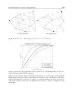
Fig. 2. The reflection coefficient ( , dB) versus frequency (GHz) plot for the
antenna Designs A, B, and C generated using the Ansoft Designer. For com-
parison, the Ansoft HFSS generated reflection coefficient result of the antenna
Design B is also included.
shown in Fig. 1(a) which only requires 20 mm or 25% length
on the ground plane leaving enough space for the RF circuitry.
For all the designs, the pentagon shape slot and stub dimensions
are kept invariant, which were selected after parametric study
but not shown here for the sake of brevity. The thickness “h” of
the substrate material is kept 1.58 mm for all the designs. For
the tilted feed line Designs B & C, the feed line is rotated by
15
. The antenna is fed using a 50 coaxial SMA connector
connected to 50
microstrip transmission feed line. The
ground plane size is 50 mm
80 mm for all the designs which
is similar in size to several portable wireless cards. The ground
plane size selection is also based on the study presented in [5],
[6] on the microstrip slot antennas.
B. Impedance and Radiation Characteristics
The reflection coefficient results for the three Designs A, B,
and C are shown below in Fig. 2 obtained using the Ansoft
Designer simulations, which considers infinite substrate mate-
rial but a finite ground plane size of 50 mm
80 mm. The
tilted feed line Design B was also simulated using the Ansoft
HFSS to observe effect on the antenna performance of the fi-
nite substrate size, in addition to other finite dimensions of the
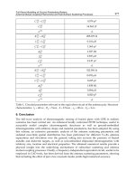
Fig. 3. Gain radiation patterns of the antenna Design B at frequencies
(a) 4 GHz, (b) 7 GHz, and (c) 10 GHz within the UWB range.
antenna. It also includes the SMA connector effects on the an-
tenna performance which is close to the antenna geometry. The
HFSS simulated reflection coefficient result is shown in Fig. 2
along with the Designer simulated reflection coefficient data.
The impedance bandwidth is generally defined for range of the
frequencies which satisfy the VSWR 2:1 or the reflection coef-
ficient,
criteria. It is observed that, for the an-
tenna Design A, bandwidth is 106% (2.6–8.4 GHz with respect
to the (w.r.t.) center frequency). For the antenna Design B, band-
width is 124% covering a frequency range from 2.65–11.3 GHz.
The antenna Design C showed a bandwidth from 2.4–9 GHz,
Authorized licensed use limited to: Phan Phuong. Downloaded on October 6, 2009 at 04:47 from IEEE Xplore. Restrictions apply.
RAJGOPAL AND SHARMA: INVESTIGATIONS ON UWB PENTAGON SHAPE MICROSTRIP SLOT ANTENNA 1355
Fig. 4. The antenna Design B results for the (a) gain (dBi) versus frequency
(GHz) at the broadside angle
, and (b) Peak gain (dBi) versus fre-
quency (GHz).
which is 116%. Similarly, the Design B, also simulated using
the HFSS, showed a bandwidth of 127% (2.8–12.6 GHz). There
are visible multiple resonances within the bandwidth, which
when joins provide impedance bandwidth exceeding the UWB
requirement of 110% (3.1–10.6 GHz). It can be observed that,
the Designs B & C with rotated feed lines exhibit enhanced
bandwidth than Design A which uses straight feed line. It is also
evident that, the antenna Design B provides the maximum band-
width among all. Further, the antenna Design B, which was sim-
ulated using both the Designer and HFSS programs, predicted
almost similar bandwidths of 124% and 127%, respectively, and
thus they agree well.
Fig. 3(a)–(c) shows the radiation patterns of the antenna De-
sign B within the UWB range obtained using the HFSS sim-
ulations. The co-polarization (
at plane and at
plane) and cross-polarization ( at plane
and
at plane) components gain patterns are plotted
at frequencies 4 GHz [Fig. 3(a)], 7 GHz [Fig. 3(b)], and 10 GHz
[Fig. 3(c)]. It is evident that, near omni-directional radiation pat-
terns can be obtained, which deteriorate towards the higher fre-
quency end. The radiation patterns variation within the band-
width is attributed to the irregular pentagon shapes of both the
slot and the stub, and its effective electrical dimension varia-
tion with the frequency. This can generate undesired current
distributions at higher frequencies, which is responsible for the
pattern deterioration at higher frequency end. It can also be ob-
served that, the cross-polarization components increase with the
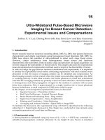
Fig. 5. (a) Geometry of the antenna Design B backed by a reflecting sheet at
a spacing of d from the antenna, and its effect on the (b) reflection coefficient
(
, dB).
increase in frequency, which is attributed to the pentagon shape
stub and tilt of the feed line.
The co- and cross-polarization components gain values at the
broadside angle
for both the and 90 cut
planes, and the peak gain values with the frequency variation
are also shown plotted in Fig. 4(a) and (b), respectively. An ex-
amination of Fig. 4(a) reveals that, the co-polarization gain com-
ponents vary from 5.80 dBi at 2.80 GHz (start of the bandwidth)
to almost 0 dBi as frequency exceeds 8 GHz, and then it become
4.10 dBi at 12.60 GHz (end of the bandwidth). Similarly,
Fig. 4(b) shows that the peak gain varies between 3.00–6.25 dBi
from around 3.50–13.0 GHz. Therefore, the peak gain variation
is around 3.25 dBi for most of the frequencies falling within
the UWB range, though at 3.10 GHz the peak gain increases to
7.50 dBi. Thus the antenna radiates well throughout the range.
III. E
FFECT OF REFLECTING SHEET ON ANTENNA
PERFORMANCE
The effect of a conducting reflecting sheet on back of the an-
tenna Design B on the impedance matching and radiation pat-
tern performance was also studied to see, if the reflecting sheet
can be used to provide unidirectional radiation patterns such as
in the case of a microstrip patch antenna [1], [2]. A square re-
flecting sheet of dimension 50 mm
50 mm is placed at spacing
“d” from the antenna, as shown in Fig. 5(a). The spacing “d” was
Authorized licensed use limited to: Phan Phuong. Downloaded on October 6, 2009 at 04:47 from IEEE Xplore. Restrictions apply.
1356 IEEE TRANSACTIONS ON ANTENNAS AND PROPAGATION, VOL. 57, NO. 5, MAY 2009
Fig. 6. Gain radiation patterns of the antenna backed by a reflecting sheet at or 10 mm within the UWB range frequencies (a) 4 GHz, (b) 5 GHz,
(c) 6 GHz, (d) 7 GHz, (e) 9 GHz, and (f) 10 GHz.
varied from 5–25 mm at a step of 5 mm for the parametric study.
All the design parameters of the antenna were kept the same
including thickness of the substrate material. Fig. 5(b) shows
the reflection coefficient variation versus frequency with the re-
flecting sheet spacing variation from
to 25 mm. From
Fig. 5(b) it can be observed that, between
to 15 mm,
the antenna shows matching level starting from about
5dBto
better. However, for
and , the antenna is
matched better than
10 dB level from almost 2.50–11.50 GHz.
For
case, the impedance bandwidth is about 129%
(2.5–11.5 GHz).
For obtaining directional radiation patterns within the UWB
range, a combined spacing between
and 10 mm can
be used. Fig. 6(a)–(f) show the gain radiation patterns with
or 10 mm spacing for frequencies in the UWB range, i.e.,
4, 5, 6, 7, 9, and 10 GHz, respectively generated using the HFSS
simulations. For the lower (3–7 GHz) and upper (8–11 GHz)
halves of the frequencies
and spac-
ings are found suitable, respectively. An evaluation of the ra-
diation patterns from Fig. 6(a)–(f) reveals that, the patterns are
fairly directional at the broadside angle (gain variation between
3–8 dBi) with front-to-back (F/B) ratios between 7–15 dB. The
patterns also show asymmetry and scan for some of the frequen-
cies providing beam peak gain values between 4–8 dBi at
angles other than the broadside angle . Not presented
here, but a single spacing
can also be used to
achieve directional patterns but with slightly reduced direction-
ality. This antenna can be further improved to achieve better
antenna performance characteristics by implementing a recon-
figurable spacing “d”. Thus, a directive antenna within the UWB
range can be obtained using the proposed slot antenna and a re-
flective conducting sheet, which is also planar and compact in
size. It can be used for some wireless communication applica-
tions if matching criteria of
is acceptable. Further,
this can also be used to reduce the back lobe radiation in hand-
held devices.
Authorized licensed use limited to: Phan Phuong. Downloaded on October 6, 2009 at 04:47 from IEEE Xplore. Restrictions apply.
RAJGOPAL AND SHARMA: INVESTIGATIONS ON UWB PENTAGON SHAPE MICROSTRIP SLOT ANTENNA 1357
Fig. 7. (a) S-parameters (dB) versus frequency (GHz), and (b) phase (de-
grees) versus frequency (GHz) plots for the transmit-receive antenna system.
IV. VERIFICATION OF THE ANTENNA
The antenna was verified using the HFSS simulation for
the UWB communications using the technique outlined in
[19], [20], where a transmit/receive antenna combination was
considered. Both transmit and receive antennas were similar
(Design B) and placed 100 mm apart facing each other as
suggested in [19]. This transmit-receive antenna combination
can also be considered as a two-port network. The S-param-
eters and
phase versus frequency variations are shown in
Fig. 7(a) and (b). The reflection coefficient results show similar
impedance matching behavior for most of the frequencies,
except that at the start and end of the bandwidth they do not
overlap. The parameters
provide all the important
system parameters in terms of the gain, impedance matching,
polarization matching, path loss and phase delay. Therefore,
these parameters can be used to predict performance of the
UWB antenna system which is frequency dependent [19]. From
Fig. 7(a) it can be observed that, the transmission coefficients
of the antenna system cover the UWB frequency
range within near to the 10 dB variation. Further as expected,
the
phase is nonlinear within the UWB range [shown in
Fig. 7(b)]. The phase centers vary with frequency because the
Fig. 8. (a) Comparison of the simulated and measured reflection coefficient
(
, dB) results for the fabricated prototype antenna shown in Fig. 1(b), and (b).
Measured group delay for the transmit-receive combination of the antennas
when facing each other.
antenna radiation behavior is dependent upon the effective
antenna dimension, which changes with frequency for a given
physical antenna dimension.
Two prototypes of the proposed antenna Design C were fab-
ricated. The photograph of one of them is already shown in
Fig. 1(b). Since the previously considered FR-4 substrate thick-
ness of
was not readily available in the Antenna
and Microwave Laboratory (AML), being developed at the San
Diego State University, therefore, the substrate thickness used
for the fabrication was
. The antenna was again
simulated using the HFSS for this substrate thickness, so that
it can be compared with the measured data. The antenna re-
flection coefficient was measured using a HP8510C Vector Net-
work Analyzer. The measured reflection coefficient along with
the simulated data is shown plotted in Fig. 8(a). The measured
impedance bandwidth w.r.t.
is 117% which
covers a frequency range from 2.6–10 GHz. In comparison to
this, the simulated bandwidth is 115% (2.5–9.3 GHz). Both sim-
ulated and measured results show multiple resonances which are
responsible for such a wide bandwidth performance. The slight
variation in frequency range can be attributed the fabrication er-
rors. Thus, it can be observed that, the simulated and measured
Authorized licensed use limited to: Phan Phuong. Downloaded on October 6, 2009 at 04:47 from IEEE Xplore. Restrictions apply.
1358 IEEE TRANSACTIONS ON ANTENNAS AND PROPAGATION, VOL. 57, NO. 5, MAY 2009
results are in good agreement. The antenna was also experimen-
tally verified for the group delay using the two antenna arrange-
ment [20], where the transmit and receive antennas are facing
each other while connected to the two ports of the Network An-
alyzer. The 100 mm spacing between the antennas is equivalent
to
(free space wavelength) at the 3 GHz and at 10 GHz.
The group delay result is shown in Fig. 8(b). The ripples may
be attributed to the scattering effect from the network cables. It
can be observed that, the group delay between the antennas is
around 0.7 ns and varies by 0.125 ns within the bandwidth. Thus
the antenna shows fairly constant group delay.
V. C
ONCLUSION
In this paper, a planar ultrawideband (UWB) pentagon
shape microstrip slot antenna is investigated for the impedance
matching and radiation pattern characteristics. This antenna
occupies only 25% space on the 50 mm
80 mm size ground
plane along the length. The antenna can find applications in
portable wireless communication devices. Both straight feed
line and tilted feed line designs were investigated with two
different substrate materials of the same thickness. It was
observed that, for the tilted feed line Design B an impedance
bandwidth of 124% (2.65–11.3 GHz) can be obtained, which
exceeds the required UWB range of 110% (3.1–10.6 GHz).
However, all three antenna Designs A, B, and C almost met
the UWB frequency range requirements, and provided nearly
omni-directional radiation patterns. Further, by employing a
conducting reflecting sheet on the back of the antenna, di-
rectional radiation patterns can be obtained within the UWB
range but with the reduced matching criteria. It can be used not
only to get directive antenna within the UWB range but also
to reduce the back lobe radiation. The measured impedance
bandwidth of the fabricated antenna showed good agreement
with the simulated data. The transmit/receive combination of
the proposed antenna showed acceptable UWB communication
performance in terms of the S-parameters and group delay.
A
CKNOWLEDGMENT
Authors would also like to thank C. Meagher for helping in
the measurements, and the anonymous reviewer’s comments
that helped in improving the presentation of this paper.
R
EFERENCES
[1] R. Garg, P. Bhartia, I. Bahl, and A. Ittipiboon, Microstrip Antenna De-
sign Handbook. Norwood, MA: Artech House, 2001.
[2] J. L. Volakis, Antenna Engineering Handbook, 4th ed. New York:
McGraw Hill, 2007.
[3] A. A. Eldek, A. Z. Elsherbeni, and C. E. Smith, “Microstrip-fed printed
lotus antenna for wideband wireless communication system,” IEEE An-
tennas Propag. Mag., vol. 46, no. 6, pp. 164–173, Dec. 2004.
[4] A. M. Abbosh, M. E. Bialkowski, J. Maziersha, and M. V. Jacob,
“A planar UWB antenna with signal rejection capability in the 4–6
GHz band,” IEEE Microw. Wireless Compon. Lett., vol. 16, no. 5, pp.
278–280, May 2006.
[5] S. K. Sharma, L. Shafai, and N. Jacob, “Investigation of wide-band
microstrip slot antenna,” IEEE Trans. Antennas Propag., vol. 52, no. 3,
pp. 865–872, Mar. 2004.
[6] S. I. Latif, L. Shafai, and S. K. Sharma, “Bandwidth enhancement
and size reduction of microstrip slot antennas,” IEEE Trans. Antennas
Propag., vol. 53, no. 3, pp. 994–1003, Mar. 2005.
[7] Y. F. Liu, K. L. Lau, Q. Xue, and C. H. Chan, “Experimental studies of
printed wide-slot antenna for wide-band applications,” IEEE Antennas
Wireless Propag. Lett., vol. 3, pp. 273–275, 2004.
[8] P. Li, J. Liang, and X. Chen, “Study of printed elliptical/circular slot an-
tennas for ultrawideband applications,” IEEE Trans. Antennas Propag.,
vol. 54, no. 6, pp. 1670–1675, June 2006.
[9] R. Chair, A. A. Kishk, K. F. Lee, C. E. Smith, and D. Kajfez, “Mi-
crostrip line and CPW fed ultrawideband slot antennas with u-shaped
tuning stub and reflector,” Progr. Electromagn. Res., PIER, vol. 56, pp.
163–182, 2006.
[10] S Y. Lin, H R. Huang, C W. Guan, and S A. Yeh, “A novel com-
pact slot antenna for ultra-wideband communication,” in Proc. IEEE
Antennas Propag. Society Int. Symp., HI, 2007, pp. 5123–5126.
[11] I T. Tang, D B. Lin, G H. Liou, J H. Horng, and C M. Li, “A
compact slot UWB antenna with CPW-fed,” in Proc. IEEE Antennas
Propag. Society Int. Symp., HI, 2007, pp. 5143–5146.
[12] J Y. Jan and C Y. Hsiang, “Microstrip-line fed printed slot antenna
for ultra-wideband operation,” in Proc. IEEE Antennas Propag. Society
Int. Symp., HI, 2007, pp. 5139–5142.
[13] S. H. Choi, J. K. Park, S. K. Kim, and J. Y. Park, “A new ultra-wideband
antenna for UWB applications,” Microw. Opt. Technol. Lett., vol. 40,
no. 5, pp. 399–401, Mar. 5, 2004.
[14] A. Vasylchenko, W. D. Raedt, and G. A. E. Vandenbosch, “Electric
and magnetic type compact UWB antenna using u-shaped slot with
band-rejection characteristic,” in Proc. IEEE Antennas Propag. Society
Int. Symp., HI, 2007, pp. 4617–4620.
[15] J M. Ju, G T. Jeong, J H. Yoon, C S. Kim, H S. Kim, and K S.
Kwak, “Design of multiple u-shaped slot microstrip patch antenna in
5 GHz band WLAN,” IEICE Trans. Commun., vol. E88-B, no. 2, pp.
821–825, Feb. 2005.
[16] T. Dissanayke and K. P. Esselle, “UWB performance of compact
l-shaped wide slot antennas,” IEEE Trans. Antennas Propag., vol. 56,
no. 4, pp. 1183–1187, Apr. 2008.
[17] A. M. Abbosh and M. E. Bialkowski, “Design of planar ultrawideband
planar monopole slot antennas of circular and elliptical shapes,” IEEE
Trans. Antennas Propag., vol. 56, no. 1, pp. 17–23, Jan. 2008.
[18] Ansoft Corporations, Designer and High Frequency Structure Simu-
lator (HFSS) [Online]. Available: www.ansoft.com
[19] Z. N. Chen and T. S. P. See, “Antennas for UWB applications,” in
Antennas for Portable Devices, Z. N. Chen, Ed. Hoboken, NJ: Wiley,
2007.
[20] Z. N. Chen, X. H. Wu, H. F. Li, N. Yang, and M. Y. W. Chia, “Consid-
erations for source pulses and antennas in UWB radio systems,” IEEE
Trans. Antennas Propag., vol. 52, no. 7, pp. 1739–1748, Jul. 2004.
Sunil Kumar Rajgopal was born in Tuticorin, Tamil
Nadu, India, in 1985. He received the B.Eng. degree
in electronics and telecommunication from Thakur
College of Engineering and Technology, Mumbai,
India, in 2006, and the M.Sc. degree in electrical
engineering from San Diego State University, San
Diego, California, in 2008.
His main research interests are in small, planar
and broadband antennas including ultrawideband
antennas for handheld wireless applications.
Authorized licensed use limited to: Phan Phuong. Downloaded on October 6, 2009 at 04:47 from IEEE Xplore. Restrictions apply.
RAJGOPAL AND SHARMA: INVESTIGATIONS ON UWB PENTAGON SHAPE MICROSTRIP SLOT ANTENNA 1359
Satish Kumar Sharma (M’00–SM’04) was born in
Sultanpur, Uttar Pradesh, India, in 1970. He received
the B.Tech. degree from Kamla Nehru Institute of
Technology, Sultanpur, India and the Ph.D. degree
from the Institute of Technology, Banaras Hindu Uni-
versity, Varanasi, India, in 1991 and 1997, respec-
tively, both in electronics engineering.
From February 1992 to December 1993, first he
was a Lecturer and then Project Officer at Kamla
Nehru Institute of Technology, Sultanpur and the
Institute of Engineering and Rural Technology,
Allahabad, respectively. From December 1993 to February 1999, he was a
Research Scholar, and then Junior/Senior Research Fellow of the Council of
Scientific and Industrial Research (CSIR) in Department of Electronics Engi-
neering, Institute of Technology, Banaras Hindu University. From March 1999
to April 2001, he was a Postdoctoral Fellow in the Department of Electrical and
Computer Engineering, University of Manitoba, Manitoba, Canada. He was
a Senior Antenna Engineer with InfoMagnetics Technologies Corporation in
Winnipeg, Manitoba, Canada, from May 2001 to August 2006. Simultaneously,
he was also a Research Associate at University of Manitoba from June 2001 to
August 2006. In August 2006, he joined San Diego State University (SDSU),
San Diego, CA, as an Assistant Professor in the Department of Electrical and
Computer Engineering. Here, he has developed an Antenna Laboratory, teaches
courses in applied electromagnetics, and advises several graduate students.
He is author/coauthor of approximately 75 research papers published in the
refereed international journals and conferences, in addition to several academic
and industrial technical reports. He also holds one U.S. and one Canadian
patent. His main research interests are in microstrip antennas, ultrawide
bandwidth antennas, reconfigurable antennas, feeds for reflector antennas,
waveguide horns and polarizers, phased array antennas, wire antennas, and RF
MEMS microwave passive components.
Dr. Sharma is also a registered Professional Engineer (P. Eng.) in the
Province of Manitoba, Canada. He received the Young Scientist Award from
the URSI Commission B, Field and Waves, during the URSI Triennial In-
ternational Symposium on Electromagnetic Theory, Pisa, Italy, in 2004. He
is a reviewer of research papers for the IEEE T
RANSACTIONS ON ANTENNAS
AND
PROPAGATION, IEEE TRANSACTIONS ON MICROW AVE THEORY AND
TECHNIQUES, IEEE ANTENNAS AND WIRELESS PROPAGATION LETTERS, and
IET’s Microwave and Antennas Propagation journals. He has served on the
Technical Program Committee and Steering Committee of the IEEE Antennas
and Propagation Symposia. He was Chair of the Student Paper Contest of the
IEEE Antennas and Propagation Society International Symposium 2008 held
in San Diego.
Authorized licensed use limited to: Phan Phuong. Downloaded on October 6, 2009 at 04:47 from IEEE Xplore. Restrictions apply.