Designation: C 186 – 98 - Heat of Hydration of Hydraulic Cement1 ppt
Bạn đang xem bản rút gọn của tài liệu. Xem và tải ngay bản đầy đủ của tài liệu tại đây (97.02 KB, 6 trang )
Designation: C 186 – 98
Standard Test Method for
Heat of Hydration of Hydraulic Cement
1
This standard is issued under the fixed designation C 186; the number immediately following the designation indicates the year of
original adoption or, in the case of revision, the year of last revision. A number in parentheses indicates the year of last reapproval. A
superscript epsilon (e) indicates an editorial change since the last revision or reapproval.
1. Scope
1.1 This test method covers the determination of the heat of
hydration of a hydraulic cement by measuring the heat of
solution of the dry cement and the heat of solution of a separate
portion of the cement that has been partially hydrated for 7 and
for 28 days, the difference between these values being the heat
of hydration for the respective hydrating period.
1.2 The results of this test method may be inaccurate if
some of the components of the hydraulic cement are insoluble
in the nitric acid/hydrofluoric acid solution.
1.3 The values stated in SI units are to be regarded as the
standard. The values given in parentheses are for information
only.
1.4 Values in SI units shall be obtained by measurement in
SI units or by appropriate conversion, using the Rules for
Conversion and Rounding given in Standard IEEE/ASTM SI
10, or measurements made in other units.
1.5 This standard does not purport to address all of the
safety concerns, if any, associated with its use. It is the
responsibility of the user of this standard to establish appro-
priate safety and health practices and determine the applica-
bility or regulatory limitations prior to use.
2. Referenced Documents
2.1 ASTM Standards:
C 109 Test Method for Compressive Strength of Hydraulic
Cement Mortars (Using 2-in. or 50-mm Cube Specimens)
2
C 114 Test Methods for Chemical Analysis of Hydraulic
Cement
2
C 670 Practice for Preparing Precision and Bias Statements
for Test Methods for Construction Materials
3
C 1005 Specification for Weights and Weighing Devices for
Use in the Physical Testing of Hydraulic Cements
2
E 11 Specification for Wire-Cloth Sieves for Testing Pur-
poses
4
IEEE/ASTM SI 10 Standard for Use of the International
System of Units (SI): The Modern Metric System
4
3. Significance and Use
3.1 The purpose of this test is to determine if the hydraulic
cement under test meets the heat of hydration requirement of
the applicable hydraulic cement specification.
3.2 This test may also be used for research purposes when it
is desired to determine the heat of hydration of hydraulic
cement at any age.
NOTE 1—When tests are performed for research purposes, useful
additional information can be obtained by determining fineness, chemical
and compound compositions.
3.3 Determination of the heat of hydration of hydraulic
cements provides information that is helpful for calculating
temperature rise in mass concrete.
4. Apparatus
4.1 Calorimetric Apparatus:
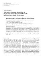
4.1.1 Calorimeter—The calorimeter, such as that illustrated
in Fig. 1 shall consist of a 0.5-L (1-pt), wide-mouth vacuum jar,
with cork stopper, or other suitable non-reactive stopper held in
a suitably insulated container (see 4.1.2) to keep the vacuum jar
in position and to protect the jar from undue temperature
fluctuations. The vacuum jar shall be coated on the interior
with a material resistant to hydrofluoric acid, such as a baked
phenolic resin, a baked vinyl chloride acetate resin, or bees-
wax. The acid-resistant coating shall be intact and free of
cracks at all times; it shall be examined frequently and renewed
whenever necessary. As another means of protecting the
vacuum jar, a plastic liner of suitable size may be used instead
of coating the interior of the jar. The contents of the vacuum jar
shall not change more than 0.001°C/min per degree difference
from room temperature when filled with 425 g of the acid
specified in 6.2, stoppered, and allowed to stand unstirred for
30 min. The temperature for this check shall approximate the
starting temperatures to be used in making the determination.
4.1.2 Insulated Container—The container shall have an
insulating layer of a material such as non-reactive foam, cotton,
or fiber-glass, which shall be at least 25 mm (1 in.) in thickness
and shall encase the sides and bottom of the vacuum jar, but
shall be so arranged as to permit easy removal of the jar.
4.1.3 Differential and Reference Thermometers—The ad-
justable differential thermometer shall be of the Beckmann-
type, graduated at least to 0.01°C, and shall have a range of
approximately 6°C. The thermometer shall be so adjusted that
the upper limit of the scale approximates room temperature.
1
This test method is under the jurisdiction of ASTM Committee C-1 on Cement
and is the direct responsibility of Subcommittee C01.26 on Heat of Hydration.
Current edition approved Jan. 10, 1998. Published July 1998. Originally
published as C 186 – 44 T. Last previous edition C 186 – 97.
2
Annual Book of ASTM Standards, Vol 04.01.
3
Annual Book of ASTM Standards, Vol 04.02.
4
Annual Book of ASTM Standards, Vol 14.02.
1
Copyright © ASTM, 100 Barr Harbor Drive, West Conshohocken, PA 19428-2959, United States.
The portion of the thermometer that will rest inside the
calorimeter shall be protected with a coating resistant to
hydrofluoric acid (see 4.1.1). The thermometer shall be
equipped with a suitable reading lens. The Beckmann ther-
mometer zero must be determined by immersion in a liquid and
comparison with the reference thermometer described. An
accurate reference thermometer of the appropriate range and
having 0.1°C divisions shall be placed in the proximity of the
calorimetric apparatus and shall be used for room temperature
readings and for establishing the Beckmann thermometer zero.
4.1.4 Funnel—The funnel through which the sample is
introduced into the calorimeter shall be of glass or plastic and
shall have a stem approximately 75 mm (3 in.) in length and
with an inside diameter of not less than 6 mm (
1
⁄
4
in.).
4.1.5 Stirring Assembly—The stirrer shall be a three-bladed
polyethylene propeller having the dimensions shown in Fig. 2,
and shall extend as closely as possible to the bottom of the
calorimeter. The motor shall be of the constant-speed type, at
least 37 W (
1
⁄
20
hp), and shall be equipped with a geared speed
reducer so that one speed, in the range of 350 to 700 r/min, can
be maintained constant.
NOTE 2—The stirrer shown in Fig. 2 may be readily made from a
commercially available three-bladed polyethylene propeller having a
propeller diameter of 34 mm (1
3
⁄
8
in.), shaft diameter of 6 mm (
1
⁄
4
in.), and
a shaft length of approximately 455 mm (18 in.). The function of the
stirrer is two-fold: to maintain uniform temperature throughout the liquid
and to supply sufficient agitation to keep the solid in suspension in the acid
mixture. Since a stirrer capable of keeping the solid in suspension
generates considerable heat in the calorimeter, it is important that the
stirrer speed, and hence the rate of heat generation, be maintained
constant. Because such constancy is difficult to achieve with other types of
motors, a synchronous motor with a geared speed reducer is recom-
mended.
FIG. 1 Calorimeter
C 186
2
4.2 Mixer—A moderate-speed mechanical mixer, such as a
milk-shake type stirrer, capable of intimately mixing the
cement and water to a uniform paste.
4.3 Storage—Storage space with temperature controlled at
23.0 6 2.0°C (73.5 6 3.5°F).
4.4 Mortar, approximately 200 mm (8 in.) in diameter, and
pestle for grinding the partially hydrated samples.
4.5 Plastic Vials, approximately 80 by 25-mm (3
5
⁄
32
by
1-in.), shell-type, with tight-fitting stoppers or caps.
4.6 Drying Oven, maintained at 100 to 110°C.
4.7 Weighing Bottles, approximately 40 mm high and 25
mm wide, with matching stoppers.
4.8 Stop Watch or Clock Timer.
4.9 Sieves, 150-µm (No. 100) and 850-µm (No. 20), con-
forming to Specification E 11.
4.10 Crucibles, platinum, 30-mL capacity, with covers, for
loss on ignition determination.
4.11 Muffle Furnace, or suitable burners capable of main-
taining a temperature of 900 to 950°C.
4.12 Analytical Balance and Analytical Weights, conform-
ing to the requirements prescribed in Test Methods C 114 for
weighing out calorimetric samples and for loss on ignition
weighings.
4.13 Weights and Weighing Devices, conforming to the
requirements of Specification C 1005. The weighing device
shall be evaluated at a total load of 1000 g.
5. Reagents and Materials
5.1 Purity of Reagents—Reagent grade chemicals shall be
used in all tests. Unless otherwise indicated, it is intended that
all reagents shall conform to the specifications of the Commit-
tee on Analytical Reagents of the American Chemical Society,
where such specifications are available.
5
Other grades may be
used, provided it is first ascertained that the reagent is of
sufficiently high purity to permit its use without lessening the
accuracy of the determination.
5.2 Hydrofluoric Acid (sp gr 1.15)—Concentrated hydrof-
luoric acid (HF).
5.3 Nitric Acid (2.00 N)—The 2.00 N HNO
3
, for use in the
calorimeter, shall be prepared and standardized in large quan-
tities. Optionally, the dilute HNO
3
may be made up with 127
mL of concentrated HNO
3
(sp gr 1.42) per litre of solution,
provided that heat capacity determinations are made with each
batch of diluted HNO
3
so prepared.
5.4 Wax—Paraffin wax, or other suitable wax, for sealing
vials.
5.5 Zinc Oxide (ZnO)—The ZnO shall be heated at 900 to
950°C for 1 h, then cooled in a desiccator, ground to pass a
150-µm (No. 100) sieve, and stored. Immediately prior to a
heat capacity determination,7goftheZnOsoprepared shall
be heated for not more than 5 min at 900 to 950°C, cooled to
room temperature in a desiccator, and weighed accurately for
introduction into the calorimeter.
NOTE 3—The rate of solution of the ZnO varies with the preliminary
treatment. The procedure described results in a product which dissolves at
about the same rate as the dry cement.
5
Reagent Chemicals, American Chemical Society Specifications, American
Chemical Society, Washington, DC. For suggestions on the testing of reagents not
listed by the American Chemical Society, see Analar Standards for Laboratory
Chemicals, BDH Ltd., Poole, Dorset, U.K., and the United States Pharmacopeia
and National Formulary, U.S. Pharmacopeial Convention, Inc. (USPC), Rockville,
MD.
FIG. 2 Stirrer
C 186
3
6. Determination of Heat Capacity of Apparatus
6.1 To determine the heat capacity of the system (that is, the
number of joules or calories required to raise the temperature
of the calorimeter and contents 1°C), measure the corrected
temperature rise obtained by dissolving7gofignited ZnO in
the specified acid mixture (see 6.2-6.7).
6.2 Transfer approximately 400 g of the 2.00 N HNO
3
,
which has been cooled to the temperature indicated by the
lower range of the Beckmann thermometer (ordinarily about 4
to 5°C below room temperature), into the vacuum jar, add 8.0
mL of HF (sp gr 1.15), weigh, and add sufficient additional
2.00 N HNO
3
to bring the total weight of the solution to 425.0
g. Then, assemble the calorimeter and start the stirring motor.
Take care that the stirrer blades or shaft do not touch the
thermometer, the sides or bottom of the jar, or the cork stopper.
The lower end of the funnel stem shall extend approximately 6
mm (
1
⁄
4
in.) below the lower surface of the stopper and at least
12 mm (
1
⁄
2
in.) above the level of the liquid. The upper end of
the bulb of the Beckmann thermometer shall be at least 38 mm
(1
1
⁄
2
in.) below the surface of the liquid. Place it at the same
depth in all determinations. After an initial stirring period of at
least 20 min to allow the temperature of the system to become
uniform, record the temperature of the room to the nearest
0.1°C, the temperature of the acid to the nearest 0.001°C,
record the time, and then immediately introduce the prepared
ZnO through the funnel at a uniform rate (see Note 4).
Complete the introduction of the ZnO in not less than 1 or more
than 2 min. Brush any ZnO clinging to the funnel stem into the
acid mixture by means of a small “camel’s-hair” brush.
NOTE 4—The temperature of the sample shall be identical with that of
the room when the sample is introduced into the calorimeter.
6.3 Read the temperature, to the nearest 0.001°C, at 20 min
and again at 40 min after beginning the introduction of the
sample. The first 20-min period is the uncorrected temperature
rise, which covers the solution period. The second 20-min
period is the rating period, and the temperature difference
between the 20 and 40-min readings is the correction to be
added to or subtracted from the uncorrected temperature rise,
according to whether the calorimeter temperature rises or falls
during the rating period.
6.4 Calculate the corrected temperature rise as follows:
R
o
5u
20
2u
0
(1)
R 5 R
o
2
~
u
40
2u
20
!
where:
R
o
5 observed temperature rise, °C,
u
20
5 calorimeter temperature at the end of the solution
period,
u
0
5 calorimeter temperature when sample was intro-
duced,
R 5 corrected temperature rise, °C, and
u
40
5 calorimeter temperature at the end of the rating
period.
6.5 Calculate the heat capacity of the calorimeter and
contents as follows (see Note 5):
C 5
W
@
1072 1 0.4
~
30 2 t
!
1 0.5
~
T 2 t
!
#
R
(2)
where:
C 5 heat capacity, kJ/°C,
W 5 mass of ZnO, g,
t 5 final temperature of the calorimeter, °C (u
20
plus
temperature, °C, at which the Beckmann thermometer
reading is zero),
T 5 temperature of the ZnO (room temperature), °C, when
introduced into the calorimeter, and
R 5 corrected temperature rise, °C.
NOTE 5—The heat of solution of ZnO is 1072 kJ/kg (256.1 cal/g) at
30°C. This value increases 0.4 kJ/kg (0.1 cal/g) for each degree decrease
in temperature below 30°C. The heat capacity of ZnO is 0.5 kJ/kg·K (0.12
cal/g·°C). The heat required to bring the ZnO to the final temperature of
the calorimeter must be included in the effective heat of solution.
6.6 If more than a trace of ZnO is found adhering to the tip
of the funnel or to the stopper when the calorimeter is opened,
reject the test.
6.7 Redetermine the heat capacity at the following times:
6.7.1 When the Beckmann thermometer is reset,
6.7.2 When a new coating is applied to thermometer, stirrer,
or flask,
6.7.3 When a new thermometer, stirrer, or flask is put in
service,
6.7.4 When a new batch of acid is used, and
6.7.5 At other times when, according to the judgment of the
operator, the need is indicated.
7. Sampling and Test Specimens
7.1 Preparation of Cement Paste—Store the cement and the
mixing water in a constant-temperature room at 23.0 6 2.0 °C
(73.5 6 3.5°F) until the materials are at ambient temperature
before preparation of the paste. Mix 150 g of cement and 60
mL of distilled water by means of a spatula, and then
vigorously stir the mixture with a mechanical stirrer for 5 min.
Place approximately equal representative portions of the paste
in four or more plastic vials, filling the vials to within about 13
mm (
1
⁄
2
in.) of the top. Immediately after filling the vials, close
them with tight-fitting stoppers or caps. (If there is any doubt
regarding the tightness of the seal, the sealed ends of the vials
should be dipped in molten paraffin wax.) Store the vials in an
upright position in a water bath at 23 6 2.0°C until the time of
test.
7.2 Preparation of Partially Hydrated Sample for Heat of
Solution Test—At the specified age of test or age of interest,
remove a vial of the partially hydrated sample from storage
within the test time tolerances of Test Method C 109, and,
during a 20-min initial stirring period of the calorimeter, break
the plastic away from the sample and rapidly crush the entire
sample with a mortar and pestle so that all the material will
pass through a 850-µm (No. 20) sieve; then quickly place the
sample in a well-stoppered weighing bottle. Take care, particu-
larly with the 7-day partially hydrated sample, to expose the
sample to the air as little as possible, and thus minimize the
action of CO
2
or the loss of moisture from the sample.
8. Procedure
8.1 Calorimetric Procedure, Dry Cement—Determine the
heat of solution of the dry cement sample according to the
C 186
4
procedure described for the heat capacity determination (Sec-
tion 6), but use a 3-g sample (weighed to the nearest 0.001 g)
of the dry cement instead of the prepared ZnO (see Note 4).
(Exercise care in securing a uniform and representative
sample.) Calculate and report the results on the ignited mass
basis (8.3). Perform the heat of solution test on the dry cement
just prior to the test on the corresponding 7-day partially
hydrated sample.
8.2 Calorimetric Procedure, Partially Hydrated Sample—
For the heat of solution of the partially hydrated sample follow
the same procedure as for the dry cement described in 8.1, but
use a 4.18 6 0.05-g calorimetric sample of the partially
hydrated cement, weighed to the nearest 0.001 g (see Note 4).
Calculate the results on the ignited basis.
8.3 Loss on Ignition:
8.3.1 Portland Cement—Immediately before and after the
calorimetric sample is being weighed out, weigh a sample of
similar amount into a platinum crucible for determination of
loss on ignition, the value to be used being the average of the
two determinations. Ignite the dry cement at 950 6 50°C for at
least 1
1
⁄
2
h or to constant mass. Immediately place the crucible
containing the sample in a desiccator and allow to cool to room
temperature; then quickly weigh the crucible. When determin-
ing the loss on ignition of the hydrated cement, first dry the
weighed sample in an oven at 100 to 110°C for 1 h; then place
the sample in a muffle furnace at 950 6 50°C overnight, or
bring to constant mass. Reduce the mass of the cement sample
that was introduced into the calorimeter to the ignited mass
basis for use in the final calculations as follows:
W
i
5
~
A/B
!
W (3)
where:
W
i
5 mass of calorimetric sample, on ignited basis, g,
A 5 mass of ignited sample, g,
B 5 mass of sample before ignition, g, and
W 5 mass of calorimetric sample, g.
8.3.2 Blended Hydraulic Cements—In addition to the pro-
cedures described in 8.3.1, determine the loss on ignition by
the reference method given in Test Methods C 114 for portland
blast-furnace slag cement and slag cement.
8.3.2.1 Determine the SO
3
content by the reference method
given in Test Methods C 114 (see Note 6). Also determine the
SO
3
content of a portion of the same cement that has not been
ignited, using the same procedure.
8.3.2.2 Calculate the percentage of mass gain from sulfide
sulfur as follows:
G 5 0.8
~
S
1
2 S
2
!
(4)
where:
G 5 percent mass gain in ignited sample,
S
1
5 SO
3
determined on ignited sample, and
S
2
5 SO
3
determined on unignited sample.
0.8 5 molecular weight ratio of 4(0)/SO
3
NOTE 6—Some of the acid used for dissolving the sample may first be
warmed in the platinum crucible to dissolve any adhering material.
8.3.2.3 Calculate the mass of the dry calorimetric sample on
the ignited basis as follows:
W
i
5
S
A 2
BG
100
D
W
B
(5)
where:
W
i
5 mass of dry calorimetric sample, on ignited basis, g,
A 5 mass of ignited dry sample, g,
B 5 mass of dry sample before ignition, g,
G 5 percentage mass gain from sulfide sulfur, and
W 5 mass of dry calorimetric sample, g.
Calculate the mass of the partially hydrated calorimetric
sample on the ignited basis as follows: (Note 7)
W
i
5
AW
S
1 2
G
100
D
B
(6)
where:
W
i
5 mass of calorimetric sample, on ignited basis, g,
A 5 mass of partially hydrated sample after ignition, g,
B 5 mass of partially hydrated sample before ignition, g,
G 5 percentage mass gain from sulfide sulfur, and
W 5 mass of partially hydrated calorimetric sample, g.
NOTE 7—An assumption is made in the calculation that the same
percentage of sulfide sulfur is present prior to ignition in the partially
hydrated sample as was determined in the cement. Tests have confirmed
that the assumption is reasonably correct and will not alter the precision
of the test method.
9. Calculation
9.1 Heat of Solution of Dry Cement—Calculate the cor-
rected temperature rise as described in 6.3 and 6.4. Also,
correct the heat of solution value if the final calorimeter
temperature of the heat of solution test is different from the
temperature of the calorimetric sample when introduced. Thus,
for the dry cement, which has a specific heat of approximately
0.8 kJ/kg·K (0.2 cal/g·°C), if the final calorimeter temperature
exceeds the temperature of the cement sample at the time it was
introduced, add a correction of 0.8 kJ/kg·K (0.2 cal/g·°C)
difference in those temperatures when calculating the heat of
solution. Calculate the heat of solution of the dry cement as
follows:
H
1
5
~
RC/W
i
!
2 0.8
~
T 2 t
d
!
(7)
where:
H
1
5 heat of solution of dry cement, kJ/kg,
R 5 corrected temperature rise, °C,
C 5 heat capacity, kJ/°C,
W
i
5 mass of sample on ignited basis, g,
T 5 room temperature, when sample is introduced, °C,
and
t
d
5 final calorimeter temperature at end of determination
on dry cement, °C.
9.2 Heat of Solution of Partially Hydrated Sample—
Calculate the heat of solution of the partially hydrated sample
in the same way as for the dry cement (9.1), except make
additional corrections, as follows:
9.2.1 Since an increase of 1°C in the temperature at which
the heat of solution test occurs causes a decrease of approxi-
mately 1.3 kJ/kg (0.3 cal/g) in the heat of solution, if the
temperature of the heat of solution test of the partially hydrated
C 186
5
sample exceeds the temperature of the dry cement determina-
tion, a correction of 1.3 kJ/kg·K (°C) difference in temperature
shall be added to the heat of solution value obtained for the
partially hydrated sample.
9.2.2 Also, correct the heat of solution value if the final
calorimeter temperature of the solution test is different from the
temperature of the calorimetric sample when introduced. Thus,
for the partially hydrated sample, which has a specific heat of
approximately 1.7 kJ/kg (0.4 cal/g) of ignited cement, if the
final calorimeter temperature exceeds the temperature of the
sample at the time it was introduced, add a correction of 1.7
kJ/kg·K (°C) difference in those temperatures when calculating
the heat of solution.
9.2.3 Calculate the heat of solution of the partially hydrated
sample as follows:
H
2
5
~
RC/W
i
!
2 1.7
~
T 2 t
h
!
2 1.3
~
t
d
2 t
h
!
(8)
where:
H
2
5 heat of solution of partially hydrated
sample, kJ/kg,
R, C, W
i
, and T 5 the same definition as in 9.1 except that
they relate to the partially hydrated
sample,
t
d
5 the same numerical value as in 9.1, and
t
h
5 final calorimeter temperature at end of
determination on partially hydrated
sample, °C.
9.3 Heat of Hydration—A final calorimeter temperature of
25°C shall be considered as the basis to which the heat of
hydration shall be referred, and the effects of variation in that
temperature should be kept in mind when considering test
results. An increase in the final temperature raises the heat of
hydration approximately 0.4 kJ/kg·K (0.1 cal/g·°C) of ignited
cement. For example, if the final temperature is 27°C, 0.8 kJ/kg
(0.2 cal/g) should be subtracted from the observed heat of
hydration in order to refer the results to 25°C. In borderline
cases, proper correction should be made for the effects of final
calorimeter temperature. Calculate the heat of hydration of the
cement to the nearest kilojoule, as follows:
H 5 H
1
2 H
2
2 0.4
~
t
h
2 25.0
!
(9)
where:
H 5 heat of hydration of ignited cement, kJ/kg,
H
1
5 heat of solution of dry cement (9.1),
H
2
5 heat of solution of partially hydrated sample (9.2),
and
t
h
5 the same numerical value as in 9.2.3
NOTE 8—To convert cal/g to kJ/kg multiply by 4.184 in accordance
with Standard IEEE/ASTM SI 10.
10. Retests
10.1 In case of failure to meet the 28-day requirement for
heat of hydration, a reserve sample of paste may be tested at a
later age and a correction of 2.1 kJ/kg (0.5 cal/g) per day of
excess age added to bring the retested heat of solution to a
28-day basis. The period over which this correction may be
made shall be limited to 4 days. In case of failure to meet the
7-day requirement, a complete retest including mixing of the
paste should be made.
11. Report
11.1 Report the following information:
11.1.1 Sample identification, which may include the source
and type of hydraulic cement and sampling date, and
11.1.2 The heat of hydration results at each of the test ages
required by the applicable specification.
12. Precision and Bias
12.1 Precision:
12.1.1 Single-Operator Precision—The single-operator
standard deviations have been found to be 12.2 kJ/kg(1s) (2.91
cal/g)(1s) and 14.8 kJ/kg(1s) (3.54 cal/g)(1s) for the determi-
nations of heat of solution and heat of hydration, respectively.
Therefore, results of two properly conducted tests by the same
operator on samples of the same cement should not differ from
each other by more than 34 kJ/kg (8 cal/g) in the determination
of heat of solution or 42 kJ/kg (10 cal/g) in the determination
of heat of hydration.
6
12.1.2 Multilaboratory Precision—The multilaboratory
standard deviations have been found to be 18.5 kJ/kg(1s) (4.42
cal/g)(1s) and 16.9 kJ/kg(1s) (4.03 cal/g)(1s) for the determi-
nations of heat of solution and heat of hydration respectively.
Therefore, results of two properly conducted tests from two
different laboratories on samples of the same cement should
not differ from each other by more than 52 kJ/kg (13 cal/g) in
the determination of heat of solution or 48 kJ/kg (11 cal/g) in
the determination of heat of hydration.
6
12.2 Bias—Since there is no accepted reference material, no
statement on bias is being made.
13. Keywords
13.1 blended cement; heat of hydration; heat of solution;
hydraulic cements; portland cement
The American Society for Testing and Materials takes no position respecting the validity of any patent rights asserted in connection
with any item mentioned in this standard. Users of this standard are expressly advised that determination of the validity of any such
patent rights, and the risk of infringement of such rights, are entirely their own responsibility.
This standard is subject to revision at any time by the responsible technical committee and must be reviewed every five years and
if not revised, either reapproved or withdrawn. Your comments are invited either for revision of this standard or for additional standards
and should be addressed to ASTM Headquarters. Your comments will receive careful consideration at a meeting of the responsible
technical committee, which you may attend. If you feel that your comments have not received a fair hearing you should make your
views known to the ASTM Committee on Standards, 100 Barr Harbor Drive, West Conshohocken, PA 19428.
This standard is copyrighted by ASTM, 100 Barr Harbor Drive, West Conshohocken, PA 19428-2959, United States. Individual
reprints (single or multiple copies) of this standard may be obtained by contacting ASTM at the above address or at 610-832-9585
(phone), 610-832-9555 (fax), or (e-mail); or through the ASTM website ().
6
These numbers represent, respectively the (1s) and (d2s) limits as described in
Practice C 670.
C 186
6


![Designation: C 109/C 109M – 99 - Compressive Strength of Hydraulic Cement Mortars (Using 2-in. or [50-mm] Cube Specimens)1 pps](https://media.store123doc.com/images/document/2014_07/10/medium_tyk1405009245.jpg)