Advanced Vehicle Technology Episode 3 Part 10 pps
Bạn đang xem bản rút gọn của tài liệu. Xem và tải ngay bản đầy đủ của tài liệu tại đây (311.04 KB, 20 trang )
Oil
separator
Receiver
Sight glass
Drier
Expansion
valve
Fan
Evaporator
coil
Evaporator
unit
Condenser
coil
Condenser
unit
Vee cylinder compressor
Starter
motor
In-line four cylinder
diesel engine
Coupling
and clutch
Fig. 13.4 Heavy duty diesel engine shaft driven compressor refrigeration unit
Sensible
heat
Latent heat of evaporation
Super
heat
Refrigerant absorbs
heat, converting
to vapour
Refrigerant rejecting
heat, converting
to liquid
Refrigerant
begins to
boil (vaporize)
Refrigerant
completely
boiled to
a saturated
vapour
Subcooled
temperature
Superheat
temperature
Saturated
temperature
Refrigerant temperature (°c)
Heat increase (J)
Fig. 13.5 Illustrative relationship between the refrigerant's temperature and heat content during a change of state
572
Latent heat of evaporation (Fig. 13.5) This is
the heat needed to completely convert a liquid to
a vapour and takes place without any temperature rise.
Superheated vapour (Fig. 13.5) This is a vapour
heated to a temperature above the saturated
temperature (boiling point); superheating can
only occur once the liquid has been completely
vaporized.
13.2 Principles of a vapour±compression cycle
refrigeration system (Fig. 13.6)
1 High pressure subcooled liquid refrigerant at
a typical temperature and pressure of 30
C and
10 bar respectively flows from the receiver to the
expansion valve via the sight glass and drier. The
refrigerant then rapidly expands and reduces its
pressure as it passes out from the valve restric-
tion and in the process converts the liquid into
a vapour flow.
2 The refrigerant now passes into the evaporator
as a mixture of liquid and vapour, its temperature
being lowered to something like À10
C with
a corresponding pressure of 2 bar (under these
conditions the refrigerant will boil in the evap-
orator). The heat (latent heat of evaporation)
necessary to cause this change of state will
come from the surrounding frozen compartment
in which the evaporator is exposed.
Condenser
coil
Discharge
line
(high pressure)
Superheated
vapour
60 10 bar
(high pressure)
C°
Superheated
vapour
8 2 bar
(low pressure)
C°
Oil
separator
Compressor
Refrigerant
rejects
heat
to
surrounding
atmosphere
Suction
line
(low pressure)
Evaporator
coil
Saturated
vapour
–10 2 bar
(low pressure)
C°
Frozen
storage
chamber
Refrigerant
absorbs
heat
from
surrounding
frozen
storage
space
Saturated
liquid
40 C 10 bar
(high
pressure)
°
Remote
feeler
bulb
Receiver
Sight
glass
Liquid
line
Drier
Liquid/vapour
mixture
40 C 10 bar°
Subcooled
liquid
30 C 10 bar°
Expansion
value
Liquid/vapour
mixture
– 10 C 2 bar
(low pressure)
°
Saturated
vapour
40 10 bar
(high pressure)
C°
6
5
4
7
8
1
2
3
Fig. 13.6 Refrigeration vapour±compression cycle
573
3 As the refrigerant moves through the evaporator
coil it absorbs heat and thus cools the space
surrounding the coil. Heat will be extracted
from the cold storage compartment until its
pre-set working temperature is reached, at this
point the compressor switches off. With further
heat loss through the storage container insula-
tion leakage, doors opening and closing and
additional food products being stored, the com-
pressor will automatically be activated to restore
the desired degree of cooling. The refrigerant
entering the evaporator tube completes the
evaporation process as it travels through the
evaporator coil so that the exit refrigerant from
the evaporator will be in a saturated vapour
state but still at the same temperature and
pressure as at entry, that is, À10
C and 2 bar
respectively.
4 The refrigerant is now drawn towards the
compressor via the suction line and this causes
the heat from the surrounding air to superheat
the refrigerant thus raising its temperature to
something like 8
C; however, there is no change
in the refrigerant's pressure.
5 Once in the compressor the superheated vapour
is rapidly compressed, consequently the super-
heated vapour discharge from the compressor is
at a higher temperature and pressure in the order
of 60
C and 10 bar respectively.
6 Due to its high temperature at the exit from the
compressor the refrigerant quickly loses heat to
the surrounding air as it moves via the discharge
line towards the condenser. Thus at the entry to
the condenser the refrigerant will be in a satur-
ated vapour state with its temperature now low-
ered to about 40
C; however, there is no further
change in pressure which is still therefore 10 bar.
7 On its way through the condenser the refrigerant
saturated vapour condenses to a saturated liquid
due to the stored latent heat in the refrigerant
transferring to the surrounding atmosphere via
the condenser coil metal walls. Note the heat
dissipated to the surrounding atmosphere by
the condenser coil is equal to the heat taken in
by the evaporator coil from the cold storage
compartment and the compressor.
8 After passing through the condenser where heat
is given up to the surrounding atmosphere the
saturated liquid refrigerant now flows into the
receiver. Here the increased space permits a
small amount of evaporation to occur, the refrig-
erant then completes the circuit to the expansion
valve though the liquid line where again heat is
lost to the atmosphere, and this brings the refrig-
erant's temperature down to something like 30
C
but without changing pressure which still
remains at 10 bar.
13.3 Refrigeration system components
A description and function of the various compon-
ents incorporated in a refrigeration system will be
explained as follows:
13.3.1 Reciprocating compressor cycle of
operation (Fig. 13.7(a±d))
Circulation of the refrigerant between the evapor-
ator and the condenser is achieved by the pumping
action of the compressor. The compressor draws in
low pressure superheated refrigerant vapour from
the evaporator and discharges it as high pressure
superheated vapour to the condenser. After flowing
through the condenser coil the high pressure refriger-
ant is now in a saturated liquid state; it then flows
to the expansion valve losing heat on the way and
thus causing the liquid to become subcooled.
Finally the refrigerant expands on its way through
the expansion valve causing it to convert into a
liquid-vapour mix before re-entering the evapor-
ator coil.
The reciprocating compressor completes a suc-
tion and discharge cycle every revolution; the out-
ward moving piston from TDC to BDC forms the
suction-stroke whereas the inward moving piston
from BDC to TDC becomes the discharge stroke.
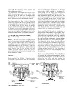
Suction stroke (Fig. 13.7(a and b)) As the crank
shaft rotates past the TDC position the piston com-
mences its suction stroke with the discharge reed
valve closed and the suction reed valve open (Fig.
13.7(a and b)). The downward sweeping piston now
reduces the cylinder pressure from P
1
to P
2
as its
volume expands from V
1
to V
2
, the vapour refrig-
erant in the suction line is now induced to enter the
cylinder. The cylinder continues to expand and to be
filled with vapour refrigerant at a constant pressure
P
1
to the cylinder's largest volume of V
3
,thatisthe
piston's outermost position BDC, see Fig. 13.8.
Discharge stroke (Fig. 13.9(c and d)) As the
crankshaft turns beyond BDC the piston begins its
upward discharge stroke, the suction valve closes and
the discharge valve opens (see Fig. 13.7(c and d)).
The upward moving piston now compresses the
refrigerant vapour thereby increasing the cylinder
pressure from P
1
to P
2
through a volume reduction
from V
3
to V
4
at which point the cylinder pressure
574
Discharge
line
Suction
line
Low pressure
vapour refrigerant
from evaporator
High pressure
vapour refrigerant
to condenser
Cylinder
head
Piston
ring
Piston
Gudgeon
pin
Connecting
rod
Cylinder
wall
Crankshaft
Suction
reed
valve
Valve
block
Crankcase
Sump
Discharge
reed
valve
(a) Piston at TDC both valves
closed high pressure vapour
trapped in discharge line and
clearance volume
(b) Piston on downward
suction stroke vapour
refrigerant drawn into
cylinder
(c) Piston at BDC both valves
closed, cylinder filled with
fresh vapour refrigerant
(d) Piston on upward discharge
stroke, suction valve closed
discharged valve open,
compressed vapour refrigerant
pumped into discharge line
Fig. 13.7 (a±d) Reciprocating compressor cycle of operation
Vapour discharge
1
4
P
2
P
1
Pressure (bar)
Clearance
volume
2
V
a
p
o
u
r
e
x
p
a
n
s
i
o
n
Vapour intake
Swept volume
V
a
p
o
u
r
c
o
m
p
re
s
s
i
o
n
3
V (TDC)
1
V
2
V
4
Volume
V (BDC)
3
Fig. 13.8 Reciprocating compressor pressure-volume cycle
575
equals the discharge line pressure; the final cylinder
volume reduction therefore from V
4
back to V
1
will
be displaced into the high pressure discharge line at
the constant discharge pressure of P
2
(see Fig. 13.8).
13.3.2 Evaporator (Fig. 13.6)
The evaporator's function is to transfer heat from
the food being stored in the cold compartment
into the circulating refrigerant vapour via the
fins and metal walls of the evaporator coil tubing
by convection and conduction respectively. The
refrigerant entering the evaporator is nearly all
liquid but as it moves through the tube coil, it
quickly reaches its saturation temperature and is
converted steadily into vapour. The heat necessary
for this change of state comes via the latent heat
of evaporation from the surrounding cold cham-
ber atmosphere.
The evaporator consists of copper, steel or stain-
less steel tubing which for convenience is shaped in
an almost zigzag fashion so that there are many
parallel lengths bent round at their ends thus
enabling the refrigerant to flow from side to side.
To increase the heat transfer capacity copper fins
are attached to the tubing so that relatively large
quantities of heat surrounding the evaporator coil
can be absorbed through the metal walls of the
tubing, see Fig. 13.15(a and b).
13.3.3 Condenser (Fig. 13.6)
The condenser takes in saturated refrigerant
vapour after it has passed though the evaporator
and compressor, progressively cooling then takes
place as it travels though the condenser coil,
accordingly the refrigerant condenses and reverts
to a liquid state. Heat will be rejected from the
refrigerant during this phase change via conduction
though the metal walls of the tubing and convec-
tion to the surrounding atmosphere.
A condenser consists of a single tube shaped
so that there are many parallel lengths with semi-
circular ends which therefore form a continuous
winding or coil. Evenly spaced cooling fins are
normally fixed to the tubing, this greatly increases
the surface area of the tubing exposed to the con-
vection currents of the surrounding atmosphere,
see Fig. 13.15(a and b).
Fans either belt driven or directly driven by an
electric motor are used to increase the amount of
air circulation around the condenser coil, this
therefore improves the heat transfer taking place
between the metal tube walls and fins to the sur-
rounding atmosphere. This process is known as
forced air convection.
13.3.4 Thermostatic expansion valve
(Fig. 13.9(a and b))
An expansion valve is basically a small orifice which
throttles the flow of liquid refrigerant being
pumped from the condenser to the evaporator;
the immediate exit from the orifice restriction will
then be in the form of a rapidly expanding re-
frigerant, that is, the refrigerant coming out from
the orifice is now a low pressure continuous liquid-
vapour stream. The purpose of the thermostatic
valve is to control the rate at which the refrigerant
passes from the liquid line into the evaporator and
Diaphragm
Tapered
valve
Outlet
to
evaporator
Inlet
from
condenser
Feeler
bulb
(attached to output
side of evaporator)
(cold)
(a) Valve closed (b) Valve open
Adjustment
screw
Spring
External
equalizer
to suction
line
Inlet
from
condenser
Feeler
bulb
(attached to output
side of evaporator)
(hot)
External
equalizer
to suction
line
Effective
expansion
orifice
Outlet
to
evaporato
r
Fig. 13.9 (a and b) Thermostatic expansion valve
576
to keep the pressure difference between the high
and low pressure sides of the refrigeration system.
The thermostatic expansion valve consists of a
diaphragm operated valve (see Fig. 13.9(a and b)).
One side of the diaphragm is attached to a spring
loaded tapered/ball valve, whereas the other side of
the diaphragm is exposed to a refrigerant which
also occupies the internal space of the remote feeler
bulb which is itself attached to the suction line tube
walls on the output side of the evaporator. If the
suction line saturated/superheated temperature
decreases, the pressure in the attached remote
feeler bulb and in the outer diaphragm chamber
also decreases. Accordingly the valve control
spring thrust will partially close the taper/ball
valve (see Fig. 13.9(a)). Consequently the reduced
flow of refrigerant will easily now be superheated
as it leaves the output from the evaporator. In
contrast if the superheated temperature rises, the
remote feeler bulb and outer diaphragm chamber
pressure also increases, this therefore will push the
valve further open so that a larger amount of refrig-
erant flows into the evaporator, see Fig. 13.9(b).
The extra quantity of refrigerant in the evaporator
means that less superheating takes place at the out-
put from the evaporator. This cycle of events is
a continuous process in which the constant super-
heated temperature control in the suction line
maintains the desired refrigerant supply to the
evaporator.
A simple type of thermostatic expansion valve
assumes the input and output of an evaporator are
both working at the same pressure; however, due to
internal friction losses the output pressure will be
slightly less than the input. Consequently the lower
output pressure means a lower output saturated
temperature so that the refrigerant will tend to
vaporize completely before it reaches the end of
the coil tubing. As a result this portion of tubing
converted completely into vapour and which is in a
state of superheat does not contribute to the heat
extraction from the surrounding cold chamber so
that the effective length of the evaporator coil is
reduced. To overcome early vaporization and
superheating, the diaphragm chamber on the
valve-stem side is subjected to the output side of
the evaporator down stream of the remote feeler
bulb. This extra thrust opposing the remote feeler
bulb pressure acting on the outer diaphragm cham-
ber now requires a higher remote feeler bulb pres-
sure to open the expansion valve.
13.3.5 Suction pressure valve (throttling valve)
(Fig. 13.10(a and b))
This valve is incorporated in the compressor
output suction line to limit the maximum suction
Intake
vapour
from
evaporator
Adjusting
nut
Piston
Spring
Valve seat
Bellows
Pin
Spring
Outlet vapour
to compressor
suction valves
Flat valve
(a) Valve fully open
Limiting
pressure
(b) Valve partially open
Fig. 13.10 Suction pressure regulating valve (throttling valve)
577
pressure generated by the compressor thereby safe-
guarding the compressor and drive engine/motor
from overload. If the maximum suction pressure is
exceeded when the refrigeration system is switched
on and started up (pull down) excessive amounts of
vapour or vapour/liquid or liquid refrigerant may
enter the compressor cylinder, which could produce
very high cylinder pressures; this would therefore
cause severe strain and damage to the engine/electric
motor components, conversely if the suction line
pressure limit is set very low the evaporator may
not operate efficiently.
The suction pressure valve consists of a com-
bined piston and bellows controlled valve subjected
to suction vapour pressure.
When the compressor is being driven by the
engine/motor the output refrigerant vapour from
the evaporator passes to the intake port of the
suction pressure valve unit; this exposes the bellows
to the refrigerant vapour pressure and temperature.
Thus as the refrigerant pressure rises the bellows
will contract against the force of the bellows spring;
this restricts the flow of refrigerant to the compres-
sor (see Fig. 13.10(a)). However, as the bellows
temperature rises its internal pressure also increases
and will therefore tend to oppose the contraction of
the bellows. At the same time the piston will be
subjected to the outlet vapour pressure from the
suction pressure valve before entering the compres-
sor cylinders, see Fig. 13.10(b). If this becomes
excessive the piston and valve will move towards
the closure position thus restricting the entry of
refrigerant vapour or vapour/liquid to the com-
pressor cylinders. Hence it can be seen that the
suction pressure valve protects the compressor
and drive against abnormally high suction line
pressure.
13.3.6 Reverse cycle valve (Fig. 13.11(a and b))
The purpose of this valve is to direct the refrigerant
flow so that the refrigerant system is in either a
cooling or heating cycle mode.
Refrigerant cycle mode (Fig. 13.11(a)) With the
pilot solenoid valve de-energized the suction pas-
sage to the slave cylinder of the reverse cycle valve
is cut off whereas the discharge pressure supply
from the compressor is directed to the slave pis-
ton. Accordingly the pressure build-up pushes the
piston and both valve stems inwards; the left
hand compressor discharge valve now closes the
From
compressor
discharge
To
condenser
coil
From
compressor
discharge
From
evaporator
coil
To compressor
suction
Compressor
discharge
valve
From
condenser
coil
To
compressor
discharge
Slave
piston
&
cylinder
Compressor
suction
valves
From
compressor
discharge
To
coil
evaporator
To compressor
suction
(a) Cooling cycle (b) Heating cycle
Fig. 13.11 (a and b) Reverse cycle valve
578
compressor discharge passage to the evaporator
and opens the compressor discharge passage to
the condenser whereas the right hand double com-
pressor discharge valve closes the condenser to
compressor suction passage and opens the eva-
porator to the compressor suction pressure.
Heat/defrost cycle mode (Fig. 13.11(b)) Energiz-
ing the pilot solenoid valve cuts off the compressor
discharge pressure to the slave cylinder of the
reverse cycle valve and opens it to the compressor
suction line. As a result the trapped refrigerant
vapour in the slave cylinder escapes to the com-
pressor suction line thus permitting the slave piston
and both valves to move to their outermost position.
The left hand compressor discharge valve now
closes the compressor discharge to the condenser
passage and opens the compressor discharge to the
evaporator passage whereas the right hand com-
pressor suction double valve closes the evaporator
to the compressor suction passage and opens the
condenser to compressor suction pressure.
13.3.7 Drier (Fig. 13.12)
Refrigerant circulating the refrigerator system
must be dry, that is, the fluid, be it a vapour or a
liquid, should not contain water. Water in the form
of moisture can promote the formation of acid
which can attack the tubing walls and joints and
cause the refrigerant to leak out. It may initiate the
formation of sludge and restrict the circulation of
the refrigerant. Moisture may also cause ice to form
in the thermostatic expansion valve which again
could reduce the flow of refrigerant. To overcome
problems with water contamination driers are nor-
mally incorporated in the liquid line; these liquid
line driers not only remove water contained in the
refrigerant, they also remove sludge and other
impurities. Liquid line driers are plumbed in on
the output side of the receiver, this is because the
moisture is concentrated in a relatively small space
when the refrigerant is in a liquid state.
A liquid line drier usually takes the form of
a cylindrical cartridge with threaded end connec-
tions so that the drier can be replaced easily when
necessary. Filter material is usually packed in at
both ends; in the example shown Fig. 13.12 there
are layers, a coarse filter, felt pad and a fine filter.
In between the filter media is a desiccant material,
these are generally of the adsorption desiccant kind
such as silica gel (silicon dioxide) or activated
alumna (aluminium oxide). The desiccant sub-
stance has microscopic holes for the liquid refriger-
ant to pass through; however, water is attracted
to the desiccant and therefore is prevented from
moving on whereas the dry (free of water) clean
refrigerant will readily flow through to the expan-
sion valve.
13.3.8 Oil separator (Fig. 13.13)
Oil separators are used to collect any oil entering
the refrigeration system through the compressor
and to return it to the compressor crankcase and
sump. The refrigerant may mix with the com-
pressor's lubrication oil in the following way:
1 During the cycle of suction and discharge refriger-
ant vapour periodically enters and is displaced
from the cylinders; however, if the refrigerant
flow becomes excessive liquid will pass through
the expansion valve and may eventually enter the
suction line via the evaporator. The fluid may
then drain down the cylinder walls to the crank-
case and sump. Refrigerant mixing with oil
dilutes it so that it loses its lubricating properties:
the wear and tear of the various rubbing com-
ponents in the compressor will therefore increase.
Contaminated
vapour/liquid
mixture from
receiver
Desiccant
dehydrating material
Dry clean
refrigeran
t
to
expansion
valve
Fine filter
Felt pad
Coarse filter
Fig. 13.12 Adsorption type liquid line drier
579
2 When the refrigerator is switched off the now
static refrigerant in the evaporator may condense
and enter the suction line and hence the com-
pressor cylinders where it drains over a period of
time into the crankcase and sump.
3 Refrigerant mixing with the lubricant in the
crankcase tends to produce oil frothing which
finds its way past the pistons and piston rings
into the cylinders; above each piston the oil will
then be pumped out into the discharge line with
the refrigerant where it then circulates. Oil does
not cause a problem in the condenser as the
temperature is fairly high so that the refrigerant
remains suspended; however, in the evaporator
the temperature is low so that the liquid oil separ-
ates from the refrigerant vapour, therefore
tending to form a coating on the inside bore of
the evaporator coil. Unfortunately oil is a very
poor conductor of heat so that the efficiency of
the heat transfer process in the evaporator is very
much impaired.
After these observations it is clear that the refrig-
erant must be prevented from mixing with the oil
but this is not always possible and therefore an oil
separator is usually incorporated on the output
side of the compressor in the discharge line which
separates the liquid oil from the hot refrigerant
vapour. An oil separator in canister form consists
of a cylindrical chamber with a series of evenly
spaced perforated baffle plates or wire mesh parti-
tions attached to the container walls; each baffle
plate has a small segment removed to permit the
flow of refrigerant vapour (Fig. 13.13), the input
from the compressor discharge being at the lowest
point whereas the output is via the extended tube
inside the container. A small bore pipe connects the
base of the oil separator to the compressor crank-
case to provide a return passage for the liquid oil
accumulated. Thus when the refrigerator is operat-
ing, refrigerant will circulate and therefore passes
though the oil separator. As the refrigerant/oil mix
zigzags its way up the canister the heavier liquid oil
tends to be attracted and attached to the baffle
plates; the accumulating oil then spreads over the
plates until it eventually drips down to the base of
the canister, and then finally drains back to the
compressor crankcase.
13.3.9 Receiver (Fig. 13.6)
The receiver is a container which collects the con-
densed liquid refrigerant and any remaining
vapour from the condenser; this small amount of
vapour will then have enough space to complete the
condensation process before moving to the expan-
sion valve.
13.3.10 Sight glass (Fig. 13.14)
This device is situated in the liquid line on the out-
put side of the receiver; it is essentially a viewing
port which enables the liquid refrigerant to be seen.
Refrigerant movement or the lack of movement
due to some kind of restriction, or bubbling caused
by insufficient refrigerant, can be observed.
13.4 Vapour±compression cycle refrigeration
system with reverse cycle defrosting
(Fig. 13.15(a and b))
A practical refrigeration system suitable for road
transportation as used for rigid and articulated
vehicles must have a means of both cooling and
Perforated
battle
plates
Vapour + oil
flow path
High pressure
vapour
refrigerant
+
oil
From
compressor
To
evaporator
High pressure
vapour refrigerant
Separated oil return to
compressor crankcase
Fig. 13.13 Oil separator
From
receiver
Liquid line
drierTo
Inspection glass
Fig. 13.14 Sight glass
580
Reverse expansion
valve – cold
(closed)
Filter
Fins
Condenser
fan
cvo
cvc
Discharge
line
Oil
separator
Reverse cycle
valve
Suction
line
Suction
pressure
valve
(throttling
valve)
Suction
valve
Suction
port
Discharge
valve
Compressor
Discharge
port
Pilot
solenoid
valve
(closed)
Remote feeler bulb
Remote feeler bulb
Evaporator coil
Drier
Thermostatic
expansion
valve
(open)
Fins
Evaporator
fan
Sight
glass
Check valve
open
cvo
Receiver
cvc
2
4
5
1
cvc
3
Condenser coil
(a) Refrigeration cycle
Fig. 13.15 (a and b) Refrigeration system with reverse cycle defrosting
581
Fins
Reverse expansion
valve – hot
(open)
Condenser coil
Remote feeler bulb Remote feeler bulb
Evaporator coil
Drier
cvo
cvo
Thermostatic
expansion
valve – cool
(closed)
Fins
Evaporator
fan
Sight
glass
Filter
Condenser
fan
Oil
separator
Reverse cycle
valve
cvo
Suction
pressure
valve
(throttling
valve)
Pilot
solenoid
valve
(open)
Suction
port
Suction
valve
Discharge
port
Compressor
Receiver
Discharge
valve
Check valve
closed
cvc
cvc
2
3
4
1
5
(
b
)
Heatin
g
and defrost c
y
cle
Fig. 13.15 Contd
582
defrosting the cold compartment. The operation of
such a system involving additional valves enables
the system to be switched between cooling and
heat/defrosting, which will now be described.
13.4.1 Refrigeration cooling cycle (Fig. 13.15(a))
With the pilot solenoid valve de-energized and the
compressor switched on and running the refriger-
ant commences to circulate through the system
between the evaporator and condenser.
Discharge line pressure from the right hand
compressor cylinder is transferred via the pilot
valve to the reverse cycle valve; this pushes the
slave piston and valves inwards to the left hand
side into the `cooling' position, see Fig. 13.15(a).
Low pressure refrigerant from the receiver flows
via the open check valve (1), sight glass and drier
to the thermostatic expansion valve where rapid
expansion in the valve converts the refrigerant to
a liquid/vapour mixture. Low pressure refrigerant
then passes through the evaporator coil where it
absorbs heat from the cold storage compartment:
the refrigerant then comes out from the evaporator
as low pressure saturated vapour. Refrigerant now
flows to the compressor suction port via the reverse
cycle valve and suction pressure valve as super-
heated vapour. The compressor now converts the
refrigerant to a high pressure superheated vapour
before pumping it to the condenser inlet via the oil
separator and reverse cycle valve; at this point the
refrigerant will have lost heat to the surroundings
so that it is now in a high pressure saturated vapour
state. It now passes through the condenser where it
gives out its heat to the surrounding atmosphere;
during this process the high pressure refrigerant is
transformed into a saturated liquid. Finally the
main liquid refrigerant flows into the receiver via
the open check valve (4) where there is enough
space for the remaining vapour to condense. This
cycle of events will be continuously repeated as the
refrigerant is alternated between reducing pressure
in the expansion valve before passing through the
evaporator to take heat from the cold chamber, to
increasing pressure in the compressor before pass-
ing through the condenser to give off its acquired
heat to the surroundings. Note check valves (1) and
(4) are open whereas check valves (2), (3) and (5)
are closed for the cool cycle.
13.4.2 Heating and defrosting cycle
(Fig. 13.15(b))
With constant use excessive ice may build up
around the evaporator coil; this restricts the air
movement so that the refrigerant in the evaporator
is unable to absorb the heat from the surrounding
atmosphere in the cold storage compartment,
therefore a time will come when the evaporator
must be defrosted.
Heating/defrosting is achieved by temporarily
reversing the refrigerant flow circulation so that
the evaporator becomes a heat dissipating coil and
the condenser converts to a heat absorbing coil.
To switch to the heat/defrosting cycle the pilot
solenoid valve is energized; this causes the solenoid
valve to block the discharge pressure and connect
the suction pressure to the servo cylinder reverse
cycle valve, see Fig. 13.15(b). Subcooled high pres-
sure liquid refrigerant is permitted to flow from the
receiver directly to the now partially opened reverse
thermostatic expansion valve (due to the now
hot remote feeler bulb's increased pressure). The
refrigerant expands in the reverse expansion valve
and accordingly converts to a liquid/vapour; this
then passes through the condenser via the open
check valve (3) in the reverse direction to the nor-
mal refrigeration cycle and in the process absorbs
heat from the surroundings so that it comes out as
a low pressure saturated vapour. The refrigerant
then flows to the compressor suction port via the
reverse cycle valve and suction pressure valve but
due to the high surrounding atmospheric tempera-
ture it is now superheated vapour. The compressor
then transforms the low pressure superheated
vapour into a high pressure superheated vapour
and discharges it to the evaporator via the oil
separator and reverse cycle valve. Hence the satur-
ated vapour stream dissipates its heat through the
tubing walls to the ice which is encasing the tubing
coil until it has all melted. The refrigerant at the exit
from the evaporator will now be in a saturated
liquid state and is returned to the receiver via the
open check valve (2), sight glass, and open check
valve (5) for the heating/defrosting cycle to be
repeated. Note during the refrigeration cycle the
condenser's reverse expansion valve and remote
feeler bulb sense the reduction in temperature at
the exit from the condenser, thus the corresponding
reduction in internal bulb pressure is relayed to the
reverse expansion valve which therefore closes
during the defrosting cycle. Defrosting is fully auto-
matic. A differential air pressure switch which
senses any air circulation restriction around the
evaporator coil automatically triggers defrosting
of the evaporator coil before ice formation can
reduce its efficiency. A manual defrost switch is
also provided.
583
14 Vehicle body aerodynamics
The constant need for better fuel economy,
greater vehicle performance, reduction in wind
noise level and improved road holding and stability
for a vehicle on the move, has prompted vehicle
manufacturers to investigate the nature of air resist-
ance or drag for different body shapes under
various operating conditions. Aerodynamics is the
study of a solid body moving through the atmosphere
and the interaction which takes place between the
body surfaces and the surrounding air with varying
relative speeds and wind direction. Aerodynamic
drag is usually insignificant at low vehicle speed but
the magnitude of air resistance becomes consider-
able with rising speed. This can be seen in Fig. 14.1
which compares the aerodynamic drag forces of a
poorly streamlined, and a very highly streamlined
medium sized car against its constant rolling resist-
ance over a typical speed range. A vehicle with a
high drag resistance tends only marginally to
hinder its acceleration but it does inhibit its maxi-
mum speed and increases the fuel consumption with
increasing speed.
Body styling has to accommodate passengers and
luggage space, the functional power train, steering,
suspension and wheels etc. thus vehicle design will
conflict with minimizing the body surface drag so
that the body shape finally accepted is nearly always
acompromise.
An appreciation of the fundamentals of aero-
dynamics and the methods used to counteract
high air resistance for both cars and commercial
vehicles will now be explained.
14.1 Viscous air flow fundamentals
14.1.1 Boundary layer (Fig. 14.2)
Air has viscosity, that is, there is internal friction
between adjacent layers of air, whenever there
is relative air movement, consequently when there
is sliding between adjacent layers of air, energy is
dissipated. When air flows over a solid surface a
thin boundary layer is formed between the main
airstream and the surface. Any relative movement
between the main airstream flow and the surface of
1600
1200
800
400
0
0 40 80 120 160
rolling resistance
Vehicle speed (km/h)
low air resistance (C = 0.25)
D
high air resistance (C = 0.5)
D
Resisting forces opposing motion (N)
Fig. 14.1 Comparison of low and high aerodynamic drag forces with rolling resistance
584
the body then takes place within this boundary
layer via the process of shearing of adjacent layers
of air. When air flows over any surface, air particles
in intimate contact with the surface loosely attach
themselves so that relative air velocity at the sur-
face becomes zero, see Fig. 14.2. The relative speed
of the air layers adjacent to the arrested air surface
film will be very slow; however, the next adjacent
layer will slide over an already moving layer so that
its relative speed will be somewhat higher. Hence
the relative air velocity further out from the surface
rises progressively between air layers until it attains
the unrestricted main airstream speed.
14.1.2 Skin friction (surface friction drag)
(Fig. 14.3)
This is the restraining force preventing a thin flat
plate placed edgewise to an oncoming airstream
being dragged along with it (see Fig. 14.3), in other
words, the skin friction is the viscous resistance
generated within the boundary layer when air flows
over a solid surface. Skin friction is dependent on the
surface area over which the air flows, the degree of
surface roughness or smoothness and the air speed.
14.1.3 Surface finish (Fig. 14.4(a and b))
Air particles in contact with a surface tend to be
attracted to it, thus viscous drag will retard the
layer of air moving near the surface. However,
there will be a gradual increase in air speed from
the inner to the outer boundary layer. The thick-
ness of the boundary layer is influenced by the
surface finish. A smooth surface, see Fig. 14.4(b),
allows the free air flow velocity to be reached
nearer the surface whereas a rough surface, see
Fig. 14.4(a), widens the boundary so that the full
air velocity will be reached further out from the
surface. Hence the thicker boundary layer asso-
ciated with a rough surface will cause more adjacent
layers of air to be sheared, accordingly there
will be more resistance to air movement compared
with a smooth surface.
14.1.4 Venturi (Fig. 14.5)
When air flows through a diverging and converging
section of a venturi the air pressure and its speed
changes, see Fig. 14.5. Initially at entry the unre-
stricted air will be under atmospheric conditions
where the molecules are relatively close together,
consequently its pressure will be at its highest and
its speed at its minimum.
As the air moves into the converging section
the air molecules accelerate to maintain the
volume flow. At the narrowest region in the
venturi the random air molecules will be drawn
Outer
layer
Inner
layer
Thickness of boundary
layer
Full velocity of air flow
V
5
V
4
V
3
V
2
V
1
Viscous
shear
Surface of body
Parabolic rise
in air layer
velocity from inner
to outer boundary
layer
Fig. 14.2 Boundary layer velocity gradient
Direction of
plate drag
Rollers
Flat plate
Airstream
Viscous
resistance
reading
Spring
scale
Fig. 14.3 Apparatus to demonstrate viscous drag
585
apart thus creating a pressure drop and a faster
movement of the air. Further downstream
the air moves into the diverging or expanding sec-
tion of the venturi where the air flow decelerates,
the molecules therefore are able to move
closer together and by the time the air reaches the
exit its pressure will have risen again and its
movement slows down.
14.1.5 Air streamlines (Fig. 14.6)
A moving car displaces the air ahead so that the air
is forced to flow around and towards the rear. The
pattern of air movement around the car can be
visualized by airstreamlines which are imaginary
lines across which there is no flow, see Fig. 14.6.
These streamlines broadly follow the contour of
the body but any sudden change in the car's shape
(a) Rough surface
(b) Smooth surface
Boundary layer
Boundary
layer
Main
airstream
Fig. 14.4 (a and b) Influence of surface roughness on boundary layer velocity profile
Airstream
High
pressure
Accelerating
flow
Low
pressure
Decelerating
flow
High
pressure
Low
speed
Exit
Entry
High
speed
Fig. 14.5 Venturi
Stagnation
position
Streamlines
Fig. 14.6 Streamline air flow around car
586
compels the streamlines to deviate, leaving zones of
stagnant air pockets. The further these streamlines
are from the body the more they will tend to
straighten out.
14.1.6 Relative air speed and pressure conditions
over the upper profile of a moving car (Figs 14.7
and 14.8)
The space between the upper profile of the hori-
zontal outer streamlines relative to the road surface
generated when the body is in motion can be con-
sidered to constitute a venturi effect, see Fig. 14.7.
Note in effect it is the car that moves whereas air
remains stationary; however, when wind-tunnel
tests are carried out the reverse happens, air is
drawn through the tunnel with the car positioned
inside on a turntable so that the air passes over and
around the parked vehicle. The air gap between the
horizontal airstreamlines and front end bonnet
(hood) and windscreen profile and the back end
screen and boot (trunk) profile produces a diver-
ging and converging air wedge, respectively. Thus
the air scooped into the front wedge can be con-
sidered initially to be at atmospheric pressure and
moving at car speed. As the air moves into the
diverging wedge it has to accelerate to maintain
the rate of volumetric displacement. Over the roof
the venturi is at its narrowest, the air movement
will be at its highest and the air molecules will be
stretched further apart, consequently there will be
a reduction in air pressure in this region. Finally the
relative air movement at the rear of the boot will
have slowed to car speed, conversely its pressure
will have again risen to the surrounding atmos-
pheric pressure conditions, thus allowing the ran-
dom network of distorted molecules to move closer
together to a more stable condition. As the air
moves beyond the roof into the diverging wedge
region it decelerates to cope with the enlarged flow
space.
As can be seen in Fig. 14.8 the pressure con-
ditions over and underneath the car's body can be
plotted from the data; these graphs show typical
pressure distribution trends only. The pressure
over the rear half of the bonnet to the mid-front
windscreen region where the airstream speed is
slower is positive (positive pressure coefficient
C
p
), likewise the pressure over the mid-position of
the rear windscreen and the rear end of the boot
where the airstream speed has been reduced is also
positive but of a lower magnitude. Conversely the
pressure over the front region of the bonnet and
particularly over the windscreen/roof leading edge
and the horizontal roof area where the airstream
speed is at its highest has a negative pressure (nega-
tive pressure coefficient C
p
). When considering the
air movement underneath the car body, the
restricted airstream flow tends to speed up the air
movement thereby producing a slight negative
pressure distribution along the whole underside of
the car. The actual pattern of pressure distribution
above and below the body will be greatly influ-
enced by the car's profile style, the vehicle's speed
and the direction and intensity of the wind.
14.1.7 Lamina boundary layer (Fig. 14.9(a))
When the air flow velocity is low sublayers within
the boundary layer are able to slide one over the
other at different speeds with very little friction;
this kind of uniform flow is known as lamina.
14.1.8 Turbulent boundary layer (Fig. 14.9(b))
At higher air flow velocity the sublayers within the
boundary layer also increase their relative sliding
speed until a corresponding increase in interlayer
friction compels individual sublayers to randomly
High pressure
low speed
High pressure
low speed
Converging
accelerating
flow
Diverging
decelerating
flow
Low pressure
high speed
Low pressure (subatmospheric pressure) high speed
Fig. 14.7 Relative air speed and pressure conditions over the upper profile of a moving car
587
Airstreamlines
Over top
Atmospheric
pressure line
Under floor
0.8
0.6
0.4
0.2
0
–0.2
–0.4
–0.6
–0.8
–1.0
–1.2
Pressure coefficient ( )
C
p
Fig. 14.8 Pressure distribution above and below the body structure
Low velocity High velocity
(a) Lamina air flow (low velocity) (b) Turbulent air flow (high velocity)
Inner layer
Outer layer
Thickness of boundary layer
Boundary layer
Lamina
flow
Eddies
(vortices)
Fig. 14.9 (a and b) Lamina and turbulent air flow
588
break away from the general direction of motion;
they then whirl about in the form of eddies, but still
move along with the air flow.
14.1.9 Lamina/turbulent boundary layer
transition point (Fig. 14.10(a and b))
A boundary layer over the forward surface of a
body, such as the roof, will generally be lamina,
but further to the rear a point will be reached called
the transition point when the boundary layer
changes from a lamina to a turbulent one, see Fig.
14.10(a). As the speed of the vehicle rises the transi-
tion point tends to move further to the front, see
Fig. 14.10(b), therefore less of the boundary layer
will be lamina and more will become turbulent;
accordingly this will correspond to a higher level
of skin friction.
14.1.10 Flow separation and reattachment
(Fig. 14.11(a and b))
The stream of air flowing over a car's body tends to
follow closely to the contour of the body unless
there is a sudden change in shape, see Fig.
14.11(a). The front bonnet (hood) is usually slightly
curved and slopes up towards the front windscreen,
from here there is an upward windscreen tilt (rake),
followed by a curved but horizontal roof; the rear
windscreen then tilts downwards where it either
merges with the boot (trunk) or continues to slope
gently downwards until it reaches the rear end of
the car.
The air velocity and pressure therefore reaches
its highest and lowest values, respectively, at the top
of the front windscreen; however, towards the rear
of the roof and when the screen tilts downwards
L = Lamina
T = Turbulent
TP = Transition point
TP
T
L
TP
T
L
(a) Low speed
(
b
)
Hi
g
h speed
Fig. 14.10 (a and b) Lamina/turbulent boundary layer transition point
589
there will be a reduction in air speed and a rise in
pressure. If the rise in air pressure towards the rear
of the car is very gradual then mixing of the air-
stream with the turbulent boundary layers will be
relatively steady so that the outer layers will be
drawn along with the main airstream, see Fig.
14.11(b). Conversely if the downward slope of the
rear screen/boot is considerable, see Fig. 14.11(a),
the pressure rise will be large so that the mixing rate
of mainstream air with the boundary layers cannot
keep the inner layers moving, consequently the
slowed down boundary layers thicken. Under
these conditions the mainstream air flow breaks
away from the contour surface of the body, this
being known as flow separation. An example of
flow separation followed by reattachment can be
visualized with air flowing over the bonnet and
front windscreen; if the rake angle between the
bonnet and windscreen is large, the streamline
flow will separate from the bonnet and then
reattach itself near the top of the windscreen or
front end of the roof, see Fig. 14.11(a). The space
between the separation and reattachment will then
be occupied by circulating air which is referred to
as a separation bubble, and if this rotary motion is
vigorous a transverse vortex will be established.
14.2 Aerodynamic drag
14.2.1 Pressure (form) drag (Figs 14.12(a±e)
and 14.13)
When viscous air flows over and past a solid form,
vortices are created at the rear causing the flow
Flow
separation
Separation
bubble
Flow
reattachment
Attached
flow
Flow
separation
Separation
bubble
Flow
separation
Attached flow
(a) Notch front and rear windscreens
(b) Very streamlined shape
Fig. 14.11 (a and b) Flow separation and reattachment
590
to deviate from the smooth streamline flow, see
Fig. 14.12(a). Under these conditions the air flow
pressure in front of the solid object will be higher
than atmospheric pressure while the pressure behind
will be lower than that of the atmosphere, conse-
quently the solid body will be dragged (sucked) in
the direction of air movement. Note that this effect
is created in addition to the skin friction drag. An
extreme example of pressure drag (sometimes
known as form drag) can be seen in Fig. 14.13
where a flat plate placed at right angles to the
air movement will experience a drag force in the
Direction
of air
flow
Vortices
(a) Flat plate
(b) Circular section (c) Circular /lobe section
(d) Aerofoil section (e) Fineness ratio (b/a)
b
a/3
a
–Ve
Fig. 14.12 (a±e) Air flow over various shaped sections
591