Advanced Vehicle Technology Episode 3 Part 7 ppsx
Bạn đang xem bản rút gọn của tài liệu. Xem và tải ngay bản đầy đủ của tài liệu tại đây (414.35 KB, 20 trang )
the tractor's rear axle to reduce the risk of jack-
knifing during an emergency application.
Parking circuit (Fig. 12.2) Applying the hand
brake lever opens the hand brake valve so that
pressurized air flows to the rear axle parking line
chambers within the double diaphragm actuators
to apply the brakes. At the same time, the mechan-
ical parking linkage locks the brake shoes in the
applied position and then releases the air from the
parking actuator chambers. This parking brake is
therefore mechanical with air assistance.
12.2.3 Trailer three line brake system (Fig. 12.3)
All trailer air braking systems have their own reser-
voir which is supplied through the emergency line
from the tractor's service reservoir.
Service line circuit (Fig. 12.3) When applying the
brakes, air pressure from the tractor's relay valve
signals the emergency relay valve to open and sup-
ply air pressure from the trailer's own reservoir to
the trailer's service line brake actuator chambers
relative to that applied to the tractor brakes. The
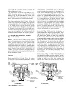
Fig. 12.2 Tractor three line brake system
Fig. 12.3 Trailer three line brake system
512
object of the separate reservoir and relay valve
installed on the trailer is to speed up the application
and release of the trailer brakes, which are at some
distance from the driver's foot control valve.
Should there be a reduction in emergency line
pressure below some predetermined minimum, the
emergency relay valve will sense this condition
and will automatically apply the trailer service
brakes.
Secondary line circuit (Fig. 12.3) The secondary
braking system of the trailer is controlled by the
hand control valve mounted in front of the driver.
Moving the hand control valve lever towards the
applied position delivers a graduable air pressure
via the secondary lines to the secondary chamber
within each double diaphragm actuator. A quick
release valve incorporated at the junction between
the trailer's front and rear brakes speeds up the
exhausting of the secondary chambers and, there-
fore, the release of the secondary brakes.
To release the trailer brakes when the trailer is
detached from the tractor caused by the exhausting
of the emergency line, a reservoir release valve is
provided which should be moved to the `open'
piston to release the trailer brakes.
12.2.4 Towing truck or tractor spring brake three
line system (Fig. 12.4)
Compressed air supply (Fig. 12.4) Air pressure is
supplied by a compressor driven off the engine.
Built into the compressor head is an unloaded
mechanism which is controlled by a governor
valve and which senses pressure change through
the wet tank. Installed on the intake side of the
compressor is an alcohol evaporator which feeds
in very small quantities of alcohol spray when the
compressor is pumping. As a result, it lowers the
freezing temperature of the wet air induced into
the compressor cylinder. When the compressor is
running light, a check valve prevents alcohol
spray entering the airstream, thereby reducing the
alcohol consumption. The compressor supplies
pressurized air to both service and secondary/
park reservoirs via non-return check valves.
Service line circuit (Fig. 12.4) When the driver
depresses the dual foot valve, air flows from
the service reservoir through the service delivery
line (yellow) directly to the front wheel service
line actuator chamber, and indirectly via a variable
load valve which regulates the air pressure,
Fig. 12.4 Towing truck or tractor spring brake three line system
513
according to the loading imposed on the rear axle,
to the rear wheel service chamber actuators. Com-
pressed air is also delivered to both the service and
the emergency line couplings via the relay valve and
the pressure protection valve. This therefore safe-
guards the tractor air supply should there be a hose
failure between the tractor and trailer. A differen-
tial protection valve is installed between the service
line and the secondary/park line to prevent both
systems operating simultaneously which would
overload the foundation brakes.
Secondary/park line circuit (Fig. 12.4) Air is sup-
plied from the secondary/park reservoir to the
hand control valve and to a pair of relay valves.
One relay valve controls the air delivered to the
spring brake actuator, the other controls the ser-
vice line air supply to the trailer brakes. With the
hand control valve in the `off' position, air is
delivered through the secondary/park line relay valve
to the spring brakes. The secondary/park spring
brakes are held in the released position due to the
compression of each power spring within the actu-
ator. As the spring brakes are being released, the
secondary line to the trailer is exhausted of com-
pressed air via its relay valve. Moving the hand
control valve lever to the `on' position progressively
reduces the secondary/park line pressure going to
the spring brake. The secondary line pressure going
to the trailer coupling increases, thereby providing
a tractor to trailer brake match. Moving the hand
control valve to the `park' position exhausts the air
from the trailer secondary line and the spring brake
secondary/park line. The tractor foundation brakes
are then applied by the thrust exerted by the power
spring within the actuator alone. The release of the
parking brake is achieved by delivering air to the
spring brake when the hand control valve is moved
to the `off' position again.
12.2.5 Towing truck or tractor spring brake
two line system (Fig. 12.5)
Compressed air supply (Fig. 12.5) The air supply
from the compressor passes through the air dryer
on its way to the multi-circuit protection. The out-
put air supply is then shared between four reser-
voirs; two service, one trailer and one secondary/
park reservoirs.
Service line circuit (Fig. 12.5) The air delivered
to the service line wheel actuator chambers is
Fig. 12.5 Towing truck or spring brake two line system
514
provided by a dual foot valve which splits the
service line circuits between the tractor's front and
rear wheels. Therefore, if one or other service line
circuit should develop a fault, the other circuit
with its own reservoir will still function. At the
same time as the tractor service brakes are applied,
a signal pressure from the foot valve passes to the
multi-relay valve. This opens an inlet valve which
permits air from the trailer reservoir to flow to the
control line (service line Ð yellow) trailer coupling.
To prevent both service line and secondary/park
line supplies compounding, that is, operating at the
same time, and overloading the foundation brakes,
a differential protection valve is included for both
the front and rear axle brakes.
Secondary/park line circuit (Fig. 12.5) A second-
ary braking system which incorporates a parking
brake is provided by spring brakes which are
installed on both front and rear axles. Control of
the spring brakes is through a hand valve which
provides an inverse signal to the multi-relay valve
so that the trailer brakes can also be applied by the
hand control valve.
With the hand control valve in the `off' position
the secondary line from the hand valve to the multi-
relay valve, and the secondary/park line, also from
the hand valve, going to the spring brake actuators
via the differential protection valves, are both
pressurized. This compresses the power springs,
thereby releasing the spring brakes. During this
period no secondary line pressure signal is passed
to the trailer brakes via the multi-relay valve.
When the hand valve is moved towards the
`applied' position, the secondary line feeding the
multi-relay valve and the secondary/park line
going to the spring brakes reduces their pressures
so that both the tractor's spring brakes and the
trailer brakes are applied together in the required
tractor to trailer proportions.
Moving the hand valve lever to the `park' posi-
tion exhausts the secondary/park line going to the
spring brakes and pressurizes the secondary line
going to the multi-relay valve. As a result, the
power springs within the spring actuators exert
their full thrust against the foundation brake cam
lever and at the same time the trailer control line
(service line) is exhausted of compressed air. Thus
the vehicle is held stationary solely by the spring
brakes.
Multi-relay valve (Fig. 12.25(a±d)) The purpose
of the multi-relay valve is to enable each of the
two service line circuits to operate independently
should one malfunction, so that trailer braking is
still provided. The multi-relay valve also enables
the hand control valve to operate the trailer brakes
so that the valve is designed to cope with three
separate signals; the two service line pressure sig-
nals controlled by the dual foot valve and the hand
valve secondary pressure signal.
Supply dump valve (Fig. 12.26(a, b and c)) The
purpose of the supply dump valve is to automat-
ically reduce the trailer emergency line pressure to
1.5 bar should the trailer service brake line fail after
the next full service brake application within two
seconds. This collapse of emergency line pressure
signals to the trailer emergency valve to apply the
trailer brakes from the trailer reservoir air supply,
overriding the driver's response.
12.2.6 Trailer two line brake system (Fig. 12.6)
The difference with the two and three line trailer
braking systems is that the two line only has a
single control service line, whereas the three line
has both a service line and a secondary line.
Control (service) line circuit (Fig. 12.6) On mak-
ing a brake application, a pressure signal from
the tractor control (service) line actuates the relay
Fig. 12.6 Trailer two line brake system
515
portion of the emergency relay valve to deliver air
pressure from the trailer reservoir to each of the
single diaphragm actuator chambers. In order to
provide the appropriate braking power according
to the trailer payload, a variable load sensing valve
is installed in the control line ahead of the emer-
gency relay valve. This valve modifies the control
line signal pressure so that the emergency relay
valve only supplies the brake actuators with suffi-
cient air pressure to retard the vehicle but not to
lock the wheels. A quick-release valve may be
included in the brake actuator feed line to speed
up the emptying of the actuator chambers to
release the brakes but usually the emergency relay
valve exhaust valve provides this function ade-
quately. If the supply (emergency) line pressure
drops below a predetermined value, then the emer-
gency portion of the emergency relay valve auto-
matically passes air from the trailer reservoir to the
brake actuators to stop the vehicle.
12.3 Air operated power brake equipment
12.3.1 Air dryer (Bendix) (Fig. 12.7(a and b))
Generally, atmospheric air contains water vapour
which will precipitate if the temperature falls low
enough. The amount of water vapour content of
the air is measured in terms of relative humidity.
A relative humidity of 100% implies that the air is
saturated so that there will be a tendency for the
air to condensate. The air temperature and pressure
Fig. 12.7(a and b) Air dryer (Bendix)
516
determines the proportion of water vapour retained
in the air and the amount which condenses.
If the saturation of air at atmospheric pressure
occurs when the relative humidity is 100% and the
output air pressure from the compressor is 8 bar,
that is eight times atmospheric pressure (a typical
working pressure), then the compressed air will
have a much lower saturation relative humidity
equal to
100
8
12:5%.
Comparing this 12.5% saturation relative
humidity, when the air has been compressed, to
the normal midday humidity, which can range
from 60% in the summer to over 90% in the winter,
it can be seen that the air will be in a state of
permanent saturation.
However, the increase in air temperature which
will take place when the air pressure rises will raise
the relative humidity somewhat before the air actu-
ally becomes saturated, but not sufficiently to
counteract the lowering of the saturation relative
humidity when air is compressed.
The compressed air output from the compressor
will always be saturated with water vapour. A safe-
guard against water condensate damaging the air
brake equipment is obtained by installing an air
dryer between the compressor and the first reservoir.
The air dryer unit cools, filters and dries all the air
supplied to the braking system. The drying process
takes place inside a desiccant cartridge which consists
of many thousands of small microcrystalline pellets.
The water vapour is collected in the pores of these
pellets. This process is known as absorption. There is
no chemical change as the pellets absorb and release
water so that, provided that the pores do not become
clogged with oil or other foreign matter, the pellets
have an unlimited life. The total surface area of the
pellets is about 464 000 m
2
.Thisisbecauseeachpellet
has many minute pores which considerably increase
the total surface area of these pellets.
Dry, clean air is advantageous because:
1 the absence of moisture prevents any lubricant in
the air valves and actuators from being washed
away,
2 the absence of moisture reduces the risk of the
brake system freezing,
3 the absence of oil vapour in the airstream caused
by the compressor's pumping action extends the
life of components such as rubber diaphragms,
hoses and `O' rings,
4 the absence of water and oil vapour prevents
sludge forming and material accumulating in
the pipe line and restricting the air flow.
Charge cycle (Fig. 12.7(a)) Air from the compres-
sor is pumped to the air dryer inlet port where it
flows downwards between the dryer body and the
cartridge wall containing the desiccant. This cools
the widely but thinly spread air, causing it to con-
dense onto the steel walls and drip to the bottom of
the dryer as a mixture of water and oil (lubricating
oil from the compressor cylinder walls). Any car-
bon and foreign matter will also settle out in this
phase. The cooled air charge now changes its direc-
tion and rises, passing through the oil filter and
leaving behind most of the water droplets and oil
which were still suspended in the air. Any carbon
and dirt which has remained with the air is now
separated by the filter.
The air will now pass through the desiccant so
that any water vapour present in the air is progres-
sively absorbed into the microcrystalline pellet
matrix. The dried air then flows up through both
the check valve and purge vent into the purge air
chamber. The dryness of the air at this stage will
permit the air to be cooled at least 17
C before
any more condensation is produced. Finally the
air now filling the purge chamber passes out to
the check valve and outlet port on its way to the
brake system's reservoirs.
Regeneration cycle (Fig. 12.7(b)) Eventually the
accumulated moisture will saturate the desiccant,
rendering it useless unless the microcrystalline
pellets are dried. Therefore, to enable the pellets
to be continuously regenerated, a reverse flow of
dry air from the purge air chamber is made to occur
periodically by the cut-out and cut-in pressure cycle
provided by the governor action.
When the reservoir air pressure reaches the max-
imum cut-out pressure, the governor inlet valve
opens, allowing pressurized air to be transferred
to the unloader plunger in the compressor cylinder
head. At the same time, this pressure signal is
transmitted to the purge valve relay piston which
immediately opens the purge valve. The accumu-
lated condensation and dirt in the base of the dryer
is then rapidly expelled due to the existing air pres-
sure in the lower part of the dryer. The sudden drop
in air pressure in the desiccant cartridge chamber
allows the upper purge chamber to discharge dry
air back through the purge vent into the desiccant
cartridge, downwards through the oil filter, finally
escaping through the open purge valve into the
atmosphere.
During the reverse air flow process, the expand-
ing dry air moves through the desiccant and effect-
ively absorbs the moisture from the crystals on its
517
way out into the atmosphere. Once the dryer has
been purged of condensation and moisture, the
purge valve will remain open until the cylinder
head unloader air circuit is permitted to exhaust
and the compressor begins to recharge the reser-
voir. At this point the trapped air above the purge
relay piston also exhausts, allowing the purge valve
to close. Thus with the continuous rise and fall of
air pressure the charge and regeneration cycles will
be similarly repeated.
A 60 W electric heater is installed in the base of
the dryer to prevent the condensation freezing dur-
ing cold weather.
12.3.2 Reciprocating air compressors
The source of air pressure energy for an air brake
system is provided by a reciprocating compressor
driven by the engine by either belt, gear or shaft-
drive at half engine speed. The compressor is usually
base- or flange-mounted to the engine.
To prevent an excessively high air working tem-
perature, the cast iron cylinder barrel is normally
air cooled via the enlarged external surface area
provided by the integrally cast fins surrounding
the upper region of the cylinder barrel. For low to
moderate duty, the cylinder head may also be air
cooled, but for moderate to heavy-duty high speed
applications, liquid coolant is circulated through
the internal passages cast in the aluminium alloy
cylinder head. The heat absorbed by the coolant is
then dissipated via a hose to the engine's own cool-
ing system. The air delivery temperature should not
exceed 220
C.
Lubrication of the crankshaft plain main and big-
end bearings is through drillings in the crankshaft,
the pressurized oil supply being provided by the
engine's lubrication system, whereas the piston and
rings and other internal surfaces are lubricated by
splash and oil mist. Surplus oil is permitted to drain
via the compressor's crankcase back to the engine's
sump. The total cylinder swept volume capacity
needed for an air brake system with possibly auxil-
iary equipment for light, medium and heavy com-
mercial vehicles ranges from about 150 cm
3
to
500 cm
3
, which is provided by either single or twin
cylinder reciprocating compressor. The maximum
crankshaft speed of these compressors is anything
from 1500 to 3000rev/min depending upon max-
imum delivery air pressure and application. The
maximum air pressure a compressor can discharge
continuously varies from 7 to 11 bar. A more typical
maximum pressure value would be 9 bar.
The quantity of air which can be delivered at
maximum speed by these compressors ranges
from 150 L/min to 500 L/min for a small to large
size compressor. This corresponds to a power loss
of something like 1.5 kW to 6 kW respectively.
Compressor operation When the crankshaft rot-
ates, the piston is displaced up and down causing
air to be drawn through the inlet port into the
cylinder on the down stroke and the same air to
be pushed out on the upward stroke through the
delivery port. The unidirectional flow of the air
supply is provided by the inlet and delivery valves.
The suction and delivery action of the compressor
may be controlled by either spring loaded disc valves
(Fig. 12.9) or leaf spring (reed) valves (Fig. 12.8).
For high speed compressors the reed type valve
arrangements tend to be more efficient.
On the downward piston stroke the delivery
valve leaf flattens and closes, thus preventing the
discharged air flow reversing back into the cylinder
(Fig. 12.8). At the same time the inlet valve is
drawn away from its seat so that fresh air flows
through the valve passage in its endeavour to fill
the expanding cylinder space.
On the upward piston stroke the inlet valve leaf
is pushed up against the inlet passage exit closing
the valve. Consequently the trapped pressurized air
is forced to open the delivery valve so that the air
charge is expelled through the delivery port to the
reservoir.
The sequence of events is continuous with a cor-
responding increase in the quantity of air delivered
and the pressure generated.
The working pressure range of a compressor
may be regulated by either an air delivery line
mounted unloader valve (Figs 12.10 and 12.11) or
an integral compressor unloader mechanism con-
trolled by an external governor valve (Fig. 12.9). A
further feature which is offered for some applica-
tions is a multiplate clutch drive which reduces
pumping and frictional losses when the compressor
is running light (Fig. 12.8).
Clutch operation (Fig. 12.8) With the combined
clutch drive compressor unit, the compressor's
crankshaft can be disconnected from the engine
drive once the primary reservoir has reached its
maximum working pressure and the compressor is
running light to reduce the wear of the rotary bear-
ings and reciprocating piston and rings and to
eliminate the power consumed in driving the com-
pressor.
The clutch operates by compressed air and is
automatically controlled by a governor valve simi-
lar to that shown in Fig. 12.9.
518
Fig. 12.8 Single cylinder air compressor with clutch drive
519
The multiplate clutch consists of four internally
splined sintered bronze drive plates sandwiched
between a pressure plate and four externally
splined steel driven plates (Fig. 12.8). The driven
plates fit over the enlarged end of the splined input
shaft, whereas the driven plates are located inside
the internally splined clutch outer hub thrust plate.
The friction plate pack is clamped together by
twelve circumferentially evenly spaced compres-
sion springs which react between the pressure
plate and the outer hub thrust plate. Situated
between the air release piston and the outer hub
thrust plate are a pair of friction thrust washers
which slip when the clutch is initially disengaged.
When the compressor air delivery has charged
the primary reservoir to its preset maximum,
the governor valve sends a pressure signal to the
clutch air release piston chamber. Immediately the
friction thrust washers push the clutch outer hub
thrust plate outwards, causing the springs to
become compressed so that the clamping pressure
between the drive and driven plates is relaxed.
As a result, the grip between the plates is removed.
This then enables the crankshaft, pressure plate,
outer hub thrust plate and the driven plates to
rapidly come to a standstill.
As the air is consumed and exhausted by brake or
air equipment application, the primary reservoir pres-
sure drops to its lower limit. At this point the gover-
nor exhausts the air from the clutch release piston
chamber and consequently the pressure springs are
free to expand, enabling the drive and driven plates
once again to be squeezed together. By these means
the engagement and disengagement of the compres-
sor's crankshaft drive is automatically achieved.
12.3.3 Compressor mounted unloader with
separate governor (Fig. 12.9(a and b))
Purpose The governor valve unit and the unloader
plunger mechanism control the compressed air out-
put which is transferred to the reservoir by causing
the compressor pumping action to `cut-out' when
the predetermined maximum working pressure is
attained. Conversely, as the stored air is consumed,
the reduction in pressure is sensed by the governor
which automatically causes the compressor to `cut-
in', thus restarting the delivery of compressed air to
the reservoir and braking system again.
Operation
Compressor charging (Fig. 12.9(a)) During the
charging phase, air from the compressor enters
the reservoir, builds up pressure and then passes
to the braking system (Fig. 12.9(a)). A small sample
of air from the reservoir is also piped to the under-
side of the governor piston via the governor inlet
port.
When the pressure in the reservoir is low, the
piston will be in its lowest position so that there is
a gap between the plunger's annular end face and
the exhaust disc valve. Thus air above the unloader
plunger situated in the compressor's cylinder head
is able to escape into the atmosphere via the gov-
ernor plunger tube central passage.
Compressor unloaded (Fig. 12.9(b)) As the reser-
voir pressure rises the control spring is compressed
lifting the governor piston until the exhaust disc
valve contacts the plunger tube, thereby closing the
exhaust valve. A further air pressure increase from
the reservoir will lift the piston seat clear of the inlet
disc valve. Air from the reservoir now flows around
the inlet disc valve and plunger tube. It then passes
though passages to the unloader plunger upper
chamber. This forces the unloader plunger down,
thus permanently opening the inlet disc valve situ-
ated in the compressor's cylinder head (Fig.
12.9(b)). Under these conditions the compressor
will draw in and discharge air from the cylinder
head inlet port, thereby preventing the compres-
sor pumping and charging the reservoir any
further. At the same time, air pressure acts on
the annular passage area around the governor
plunger stem. This increases the force pushing
the piston upwards with the result that the inlet
disc valve opens fully. When the brakes are used,
the reservoir pressure falls and, when this pressure
reduction reaches 1 bar, the control spring down-
ward force will be sufficient to push down the
governor piston and to close the inlet disc valve
initially.
Instantly the reduced effective area acting on
the underside of the piston allows the control
spring to move the piston down even further
until the control exhaust valve (tube/disc) opens.
Compressed air above the unloader plunger will
flow back to the governor unit, enter the open
governor plunger tube and exhaust into the atmos-
phere. The unloader plunger return spring now
lifts the plunger clear of the cylinder head inlet
disc, permitting the compressor to commence
charging the reservoir.
The compressor will continue to charge the sys-
tem until the cut-out pressure is reached and once
again the cycle will be repeated.
520
Fig. 12.9 Compressor mounted unloader with separate governor
521
12.3.4 Unloader valve (diaphragm type)
(Fig. 12.10(a and b))
Compressor charging (Fig. 12.10(a)) When air is
initially pumped from the compressor to the reser-
voir, the unloader valve unit non-return valve
opens and air passes from the inlet to the outlet
port. At the same time, air flows between the neck
of the exhaust valve and the shoulder of the relay
valve piston, but since they both have the same
cross-sectional area, the force in each direction is
equalized. Therefore, the relay piston return spring
is able to keep the exhaust valve closed. Air will
also move through a passage on the reservoir side
of the non-return valve to the chamber on the
plunger side of the diaphragm.
Compressor unloaded (Fig. 12.10(b)) As the reser-
voir pressure rises, the diaphragm will move
against the control spring until the governor plun-
ger has shifted sufficiently for the exhaust valve to
close (Fig. 12.10(b)). Further pressure build-up
moves the diaphragm against the control spring
so that the end of the plunger enters its bore and
opens the inlet valve. The annular end face of the
plunger will also be exposed to the air pressure, so
that the additional force produced fully opens the
inlet valve. Air now passes through the centre of
the plunger and is directed via a passage to the head
of the relay piston.
Eventually a predetermined maximum cut-out
pressure is reached, at which point the air pressure
acting on the relay piston crown overcomes the
relay return spring, causing the relay exhaust
valve to open, expelling the compressed air into
the atmosphere. This enables the compressor to
operate under no-load conditions while the reser-
voir and braking system is sufficiently charged.
Compressor commences charging (Fig. 12.10
(a and b)) As the stored air is consumed during
a braking cycle, the pressure falls until the cut-in
point (minimum safe working pressure) is reached.
At this point the control spring force equals and
exceeds the opposing air pressure force acting on
the diaphragm on the plunger side. The diaphragm
and plunger will therefore tend to move away from
the control spring until the plunger stem closes the
inlet valve. Further plunger movement pushes the
exhaust valve open so that trapped air in the relay
Fig. 12.10(a and b) Unloader valve (diaphragm type)
522
piston crown chamber is able to escape to the
atmosphere. The relay piston return spring closes
the relay exhaust valve instantly so that compres-
sion of air again commences, permitting the reser-
voir to recharge to the pressure cut-out setting.
12.3.5 Unloader valve (piston type)
(Fig. 12.11(a and b))
Purpose The unloader valve enables the compres-
sor to operate under no-load conditions, once the
reservoir is fully charged, by automatically dischar-
ging the compressor's output into the atmosphere,
and to reconnect the compressor output to the
reservoir once the air pressure in the system drops
to some minimum safe working value.
Operation
Compressor charging (Fig. 12.11(a)) When the
compressor starts to charge, air will flow to the
reservoir by way of the horizontal passage between
the inlet and outlet ports.
The chamber above the relay piston is vented to
the atmosphere via the open outlet pilot valve so
that the return spring below the relay piston is able
to keep the exhaust valve closed, thus permitting
the reservoir to become charged.
Compressor unloaded (Fig. 12.11(b)) As the reser-
voir pressure acting on the right hand end face of
the pilot piston reaches a maximum (cut-out set-
ting), the pilot piston pushes away from its inlet
seat. A larger piston area is immediately exposed to
the air pressure, causing the pilot piston to rapidly
move over to its outlet seat, thereby sealing the
upper relay piston chamber atmospheric vent. Air
will now flow along the space made between the
pilot piston and its sleeve to act on the upper face of
the relay piston. Consequently, the air pressure on
both sides of the relay piston will be equalized
momentarily. Air pressure acting down on the
exhaust valve overcomes the relay piston return
spring force and opens the compressor's discharge
to the atmosphere. The exhaust valve will then be
held fully open by the air pressure acting on the
upper face of the relay piston. Compressed air from
the compressor will be pumped directly to the
atmosphere and so the higher pressure on the reser-
voir side of the non-return valve forces it to close,
thereby preventing the stored air in the reservoir
escaping.
Compressor commencescharging (Fig. 12.11(a and b))
As the air pressure in the reservoir is discharged
and lost to the atmosphere during brake applica-
tions the reservoir pressure drops. When the pres-
sure has been reduced by approximately one bar
below the cut-out setting (maximum pressure), the
control spring overcomes the air pressure acting on
the right hand face of the pilot piston, making it
shift towards its inlet seat. The pilot piston outlet
Fig. 12.11 (a and b) Unloader valve (piston type)
523
valve opens, causing the air pressure above the
relay piston to escape to the atmosphere which
allows the relay piston return spring to close
the exhaust valve. The discharged air from the
compressor will now be redirected to recharge
the reservoir.
The difference between the cut-out and cut-in
pressures is roughly one bar and it is not adjust-
able, but the maximum (cut-out) pressure can be
varied over a wide pressure range by altering the
adjustment screw setting.
12.3.6 Single- and multi-circuit protection valve
(Fig. 12.12a)
Purpose Circuit protection valves are incorpor-
ated in the brake charging system to provide an
independent method of charging a number of reser-
voirs to their operating minimum. Where there is a
failure in one of the reservoir circuits, causing loss
of air, they will isolate the affected circuit so that
the remaining circuits continue to function.
Single element protection valve (Fig. 12.12(a))
When the compressor is charging, air pressure is
delivered to the supply port where it increases until
it is able to unseat the non-return disc valve against
the closing force of the setting spring. Air will now
pass between the valve disc and its seat before it
enters the delivery port passage on its way to the
reservoir. A larger area of the disc valve is now
exposed to air pressure which forces the disc valve
and piston to move further back against the
already compressed setting spring. As the charging
pressure in the reservoir increases, the air thrust on
the disc and piston face also rises until it eventually
pushes back the valve to its fully open position.
When the air pressure in the reservoir reaches its
predetermined maximum, the governor or unloader
valve cuts out the compressor. The light return
spring around the valve stem, together with air pres-
sure surrounding the disc, now closes the non-return
valve, thereby preventing air escaping back through
the valve. Under these conditions, the trapped air
pressure keeps the disc valve on its seat and holds the
setting spring and piston in the loaded position,
away from the neck of the valve stem. As air is
consumed from the reservoir, its pressure drops so
that the compressor is signalled to cut in again
(restarting pumping). The pressure on the compres-
sor side of the non-return valve then builds up and
opens the valve, enabling the reservoir to recharge.
Fig. 12.12 Quadruple circuit protection valve
524
Should the air pressure in one of the reservoir
systems drop roughly 2.1 bar or more, the setting
spring stiffness overcomes the air pressure acting
on the piston so that it moves against the disc valve
to close the inlet passage. The existing air pressure
stored in the reservoir will still impose a thrust
against the piston, but because the valve face area
exposed to the charge pressure is reduced by the
annular seat area and is therefore much smaller, a
pressure increase of up to 1.75 bar may be required
to re-open the valve.
A total loss of air from one reservoir will auto-
matically cause the setting spring of the respective
protection valve to close the piston against the non-
return valve.
Multi-element protection valve (Fig. 12.12) Multi-
element protection valves are available in triple and
quadruple element form. Each element contains
the cap, piston, setting spring and non-return
valve, similar to the single element protection
valve.
Charging air from the compressor enters the
supply port of the multi-element protection valve,
increasing the pressure on the inlet face of the first
and second valve element and controlling the deliv-
ery to the front and rear service reservoirs respect-
ively. When the predetermined setting pressure is
reached, both element non-return valves open, per-
mitting air to pass through the valve to charge both
service reservoirs.
The protection valves open and close according to
the governor or unloader valve cutting in or cutting
out the pumping operation of the compressor.
Internal passages within the multi-element valve
body, protected by two non-return valves, connect
the delivery from the first and second valve ele-
ments to the inlet of the third and fourth valve
elements, which control the delivery to the second-
ary/park and the trailer reservoir supplies respect-
ively. Delivery to the third and fourth valve
elements is fed from the reservoir connected to the
first and second valve element through passages
within the body.
The additional check valves located in the body of
the multi-protection valve act as a safeguard against
cross-leakage between the front and rear service
reservoirs. Failure of the front reservoir or circuit
still permits the rear service reservoir to supply the
third and fourth element valve. Alternatively, if the
rear service reservoir should fail, the front service
reservoir can cope adequately with delivering air
charge to the third and fourth reservoir.
12.3.7 Pressure reducing valve (piston type)
(Fig. 12.13(a, b and c))
Various parts of an air brake system may need to
operate at lower pressures than the output pressure
delivered to the reservoirs. It is therefore the func-
tion of the pressure reducing valve to decrease,
adjust and maintain the air line pressure within
some predetermined tolerance.
Fig. 12.13 (a±c) Pressure reducing valve (piston type)
525
Operation When the vehicle is about to start a
journey, the compressor charges the reservoirs and
air will flow through the system to the various com-
ponents. Initially, air flows through to the pressure
reducing valve supply port through the open inlet
valve and out to the delivery port (Fig. 12.13(a)). As
the air line pressure approaches its designed working
value, the air pressure underneath the piston over-
comes the stiffness of the control spring and lifts the
piston sufficiently to close the inlet valve and cut off
the supply of air passing to the brake circuit it
supplies (Fig. 12.13(b)).
If the pressure in the delivery line exceeds the
predetermined pressure setting of the valve spring,
the extra pressure will lift the piston still further
until the hollow exhaust stem tip is lifted clear of its
seat. The surplus of air will now escape through the
central exhaust valve stem into the hollow piston
chamber where it passes out into the atmosphere
via the vertical slot on the inside of the adjustable
pressure cap (Fig. 12.13(c)). Delivery line air will
continue to exhaust until it can no longer support
the control spring. At this point, the spring pushes
the piston down and closes the exhaust valve. After
a few brake applications, the delivery line pressure
will drop so that the control spring is able to
expand further, thereby unseating the inlet valve.
Hence the system is able to be recharged.
12.3.8 Non-return (check) valve (Fig. 12.14(a))
Purpose A non-return valve, sometimes known as
a check valve, is situated in an air line system where
it is necessary for the air to flow in one direction
only. It is the valve's function therefore not to
restrict the air flow in the forward direction, but
to prevent any air movement in the reverse or
opposite direction.
Operation (Fig. 12.14(a)) When compressed air
is delivered to a part of the braking system via
the non-return valve, the air pressure forces the
spherical valve (sometimes disc) head of its seat
against the resistance of the return spring. Air is
then permitted to flow almost unrestricted through
the valve. Should the air flow in the forward direc-
tion cease or even reverse, the return spring quickly
closes to prevent air movement in the opposite
direction occurring.
12.3.9 Safety valve (Fig. 12.14(b))
Purpose To protect the charging circuit of an air
braking system from excessive air pressure, safety
valves are incorporated and mounted at various
positions in the system, such as on the compressor
cylinder head, on the charging reservoir or in the
pipe line between the compressor and reservoir.
Operation (Fig. 12.14(b)) If an abnormal pressure
surge occurs in the charging system, the rise in air
pressure will be sufficient to push the ball valve
back against the regulating spring. The unseated
ball now permits the excess air pressure to escape
into the atmosphere. Air will exhaust to the atmo-
sphere until the pressure in the charging system has
been reduced to the blow-off setting determined by
the initial spring adjustment. The regulating spring
then forces the ball valve to re-seat so that no more
air is lost from the charging system.
Fig. 12.14(a and b) Non-return and safety valves
526
12.3.10 Dual concentric foot control valve
(Fig. 12.15(a and b))
Purpose The foot control valve regulates the air
pressure passing to the brake system from the reser-
voir according to the amount the foot treadle is
depressed. It also imparts a proportional reaction
to the movement of the treadle so that the driver
experiences a degree of brake application.
Operation
Applying brakes (Fig. 12.15(a)) Depressing the
foot treadle applies a force through the graduating
springs to the pistons, causing the exhaust hollow
stem seats for both pistons to close the inlet/
exhaust valves. With further depression of the
foot pedal, the piston simultaneously unseats the
inlet/exhaust valves and compressed air from the
reservoirs passes through the upper and lower
valves to the front and rear brake actuators respect-
ively (or to the tractor and trailer brake actuators
respectively).
Balancing (Fig. 12.15(a and b)) With the com-
pressed air passing to the brake actuator chambers,
air pressure is built up beneath the upper and lower
pistons. Eventually the upthrust created by this air
pressure equals the downward spring force; the
pistons and valve carrier lift and the inlet valves
close, thus interrupting the compressed air supply
to the brake actuators. At the same time, the
exhaust valves remain closed. The valves are then
in a balanced condition with equal force above and
Fig. 12.15 (a and b) Dual concentric foot valve
527
below the upper piston and with equal air pressure
being held in both halves of the brake line circuits.
Pushing the treadle down still further applies an
additional force on top of the graduating spring.
There will be a corresponding increase in the air
pressure delivered and a new point of balance will
be reached.
Removing some of the effort on the foot treadle
reduces the force on top of the graduating spring.
The pistons and valve carrier will then lift due to
the air pressure and piston return springs. When
this occurs the inlet valves remain closed and the
exhaust valves open to exhausting air pressure
from the brake actuators until a state of balance
is obtained at lower pressure.
Releasing brakes (Fig. 12.15(b)) Removing the
driver's force from the treadle allows the upper
and lower piston and the valve carrier to rise to
the highest position. This initially causes the inlet/
exhaust valves to close their inlet seats, but with
further upward movement of the pistons and valve
assembly both exhaust valves open. Air from both
brake circuits will therefore quickly escape to the
atmosphere thus fully releasing the brakes.
12.3.11 Dual delta series foot control valve
(Fig. 12.16)
Purpose The delta series of dual foot valves pro-
vide the braking system with two entirely separate
foot controlled air valve circuits but which operate
simultaneously with each other. Thus, if one half of
the dual foot valve unit should develop a fault then
the balance beam movement will automatically
ensure that the other half of the twin valve unit
continues to function.
Operation
Brakes released (12.16(a)) When the brakes are
released, the return springs push up the piston,
graduating spring and plunger assemblies for each
half valve unit. Consequently the inlet disc valves
close and the control tube shaped exhaust valves
Treadle
Balance
beam
Plunger
Air
exhausting
From
brake
actuator
Supply
port
Supply
port
Graduating
spring
Reaction
piston
Exhaust
valve
open
Inlet/
exhaust
valve
Return
spring
To
brake
actuator
Inlet
valve
open
From
reservoir
From
reservoir
To
brake
actuator
(
a
)
Brake released
(
b
)
Brake applied
Fig. 12.16(a and b) Dual delta foot control valve
528
open. This permits air to exhaust through the
centre of the piston tube, upper piston chamber
and out to the atmosphere.
Brakes applied (12.16(b)) When the foot treadle
is depressed, a force is applied centrally to the
balance beam which then shares the load between
both plunger spring and piston assemblies. The
downward plunger load initially pushes the piston
tubular stem on its seat, closing the exhaust disc
valve, and with further downward movement
unseats and opens the inlet disc valve. Air from
the reservoirs will now enter the lower piston
chambers on its way to the brake actuators via
the delivery ports.
As the air pressure builds up in the lower piston
chambers it will oppose and compress the graduat-
ing springs until it eventually closes the inlet valve.
The valve assembly is then in a lapped or balanced
position where both exhaust and inlet valves are
closed. Only when the driver applies an additional
effort to the treadle will the inlet valve again open
to allow a corresponding increase in pressure to
pass through to the brake actuator.
The amount the inlet valve opens will be pro-
portional to the graduating spring load, and the
pressure reaching the brake actuator will likewise
depend upon the effective opening area of the
inlet valve. Immediately the braking effort to the
foot treadle is charged, a new state of valve lap will
exist so that the braking power caused by the air
operating on the wheel brake actuator will be pro-
gressive and can be sensed by the driver by the
amount of force being applied to the treadle.
When the driver reduces the foot treadle load, the
inlet valve closes and to some extent the exhaust
valve will open, permitting some air to escape
from the actuator to the atmosphere via central
tube passages in the dual piston tubes. Thus the
graduating spring driver-controlled downthrust
and the reaction piston air-controlled upthrust
will create a new state of valve lap and a corres-
ponding charge to the braking power.
12.3.12 Hand control valve (Fig. 12.17(a and b))
Purpose These valves are used to regulate the
secondary brake system on both the towing tractor
Fig. 12.17 (a and b) Hand control valve
529
and on the trailer. Usually only the tractor front
axle has secondary braking to reduce the risk of
a jack-knife during heavy emergency braking.
Operation
Applying brakes (Fig. 12.17(a)) Swivelling the
handle from the released position enables the cam
follower to slide over the matching inclined cam
profile, thereby forcing the cam plate downwards
against the graduating (reaction) spring. The stiff-
ening of the reaction spring forces the piston to
move downwards until the exhaust valve passage
is closed. Further downward movement of the pis-
ton unseats the inlet valve, permitting compressed
air from the reservoir to flow through the valve
underneath the piston and out of the delivery
port, to the front brake actuator and to the trailer
brake actuator via the secondary line (blue) cou-
pling to operate the brakes.
Balancing (Fig. 12.17(a and b)) The air supply
passing through the valve gradually builds up an
opposing upthrust on the underside of the piston
until it eventually overcomes the downward force
caused by the compressed reaction spring. Sub-
sequently the piston lifts, causing the inlet valve to
close so that the compressed air supply to the brake
actuators is interrupted. The exhaust valve during
this phase still remains seated, thereby preventing
air exhaustion. With both inlet and exhaust valves
closed, the system is in a balanced condition, thus
the downward thrust of the spring is equal to the
upthrust of the air supply and the predetermined
air pressure established in the brake actuators.
Rotating the handle so that the reaction spring is
further compressed, opens the inlet valve and
admits more air at higher pressure, producing
a new point of balance.
Partially rotating the handle back to the released
position reduces some of the reaction spring down-
ward thrust so that the existing air pressure is able
to raise the piston slightly. The raised piston results
in the inlet valve remaining seated, but the exhaust
valve opens, permitting a portion of the trapped air
inside the brake actuator to escape into the atmos-
phere. Therefore the pressure underneath the pis-
ton will decrease until the piston upthrust caused
by the air pressure has decreased to the spring
downthrust acting above the piston. Thus a new
state of balance again is reached.
Releasing brakes (Fig. 12.17(b)) Returning the
handle to the released position reduces the down-
ward load of the reaction spring to fully raise the
piston. As a result, the inlet valve closes and the
exhaust valve is unseated, so that the air pressure in
the brake actuator chambers collapses as the air is
permitted to escape to the atmosphere.
12.3.13 Spring brake hand control valve
(Fig. 12.18(a, b and c))
Purpose This hand control valve unit has two
valve assemblies which, due to the cam profile
design, is able to simultaneously deliver an
`upright' and an `inverse' pressure. The valve unit
is designed to provide pressure signals via the delivery
of small volumes of air to the tractor spring brakes
and the trailer's conventional diaphragm actua-
tors. The required full volume of air is then able
to pass from the secondary/park reservoir to the
brake actuators via the relay valves to apply or
release the brakes.
Operation
Spring brake release (Fig. 12.18(a)) When the vehi-
cle is in motion with the brakes released, the upright
valve assembly inlet valve is closed and the exhaust
valve is unseated, permitting all the air in the trailer
brake actuators to be expelled. Conversely the
inverse valve assembly delivers a signal pressure
to the spring brake relay valve. This results in
the line from the secondary/park reservoir to
the tractor spring brake actuators to be open.
Thus a large volume of air will be delivered to
the air chambers controlling the compression of
the power springs and the releasing of the tractor
brakes.
Secondary brake application (Fig. 12.18(b)) As the
handle is moved across the gate to make a secondary
brake application it rotates the cam, depressing the
upright plunger. The exhaust valve closes and the
inlet valve is unseated, causing compressed air to
pass to the trailer brake actuator chambers. As the
pressure in the brake actuators increases, the air
pressure acting on top of the upright piston causes
it to move down against the upthrust exerted by the
graduating spring, closing the inlet valve. This pro-
cedure is repeated for further handle movement
until the full secondary brake position is reached
when the air pressure delivered to the trailer brake
chamber is at a maximum.
During this operation the inverse valve assem-
bly, which was delivering maximum pressure when
the handle was in the `off' position, is exhausting
530
Fig. 12.18 (a±c) Spring brake hand control valve
531