507 Mechanical Movements - Brown Part 2 docx
Bạn đang xem bản rút gọn của tài liệu. Xem và tải ngay bản đầy đủ của tài liệu tại đây (829.3 KB, 10 trang )
MECHANICAL
MOVEMENTS.
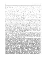
1.
Illustrates
the
transmission
of
power
by
simple
pulleys
and
an
open
belt.
In this
case
both
of the
pulleys
rotate
in the
same
direction.
2. Differs
from
i
in the
substitution
of a
crossed
belt
for
the
open
one.
In
this case
the direction
of rotation
of
the
pulleys
is
re-
versed.
By arranging
three
pulleys,
side
by
side,
upon
the
shaft
to be
driven,
the
middle
one
fast and the other two loose
upon
it,
and
using
both
an
open
and a crossed
belt,
the
direction
of
the
said shaft
is
enabled
to be
reversed without
stopping
or
reversing
the
driver. One belt
will
always
run on the
fast
pulley,
and the other on
one
of
the loose
pulleys.
The
shaft will be
driven
in one
di-
rection or
the
other,
according
as
the
open
or
crossed
belt
is on
the
fast
pulley.
3.
A
method of
transmitting
motion from
a shaft at
right
angles
to
another,
by
means
of
guide-pulleys.
There are two of these
pulleys,
side
by
side,
one
for
each
leaf
of
the
belt.
4.
A
method of
transmitting
motion from
a
shaft at
right
angles
to another whose axis
is
in
the
same
plane.
This is shown
with a
crossed
belt.
An
open
belt
may
be
used,
but
the
crossed
one
is
preferable,
as it
gives
more
surface of
contact.
5.
Resembles
i,
with the addition
of a
movable
tightening
pulley,
B.
When this
pulley
is
pressed
against
the band to take
up
the
slack,
the
belt transmits
motion from
one
of
the
larger
pulleys
to the other
;
but
when
it
is
not,
the belt
is so
slack
as not to
transmit motion.
6.
By giving
a
vibratory
motion to the
lever secured to the semi-circular
segment,
the belt attached
to the
said
segment
imparts
a
reciprocating rotary
motion
to
the
two
pul-
leys
below.
7.
A
method of
engaging,
disengaging,
and
reversing
the
upright
shaft
at the left.
The belt
is shown on
the middle one
of
the
three
pulleys
on the lower
shafts,
a,
I/,
which
pulley
is
loose,
and
consequently
no move-
ment
is
communicated
to
the
said shafts.
When the belt
is
traversed
on the left-hand
pulley,
which
is
fast
on
the
hollow
shaft,
<,
carrying
the
bevel-gear,
B,
motion
is
com-
municated
in
one direction to the
upright
shaft
;
and on its
being
traversed
on
to the
right-hand pulley,
motion is transmitted
through
the
gear,
A,
fast on the
shaft,
a,
which runs
inside
of
b,
and
the
direction of
the
upright
shaft
is
reversed.
8.
Speed-pulleys
used
for lathes and other
mechanical
tools,
for
varying
the
speed
ac-
cording
to' the
work
operated
upon.
9. Cone-pulleys
for
the
same
purpose
as
8. This
motion
is used
in
cotton
machin-
ery,
and in all machines
which
are
required
to run with a
gradually
increased
or dimin-
ished
speed.
10. Is a modification of
9,
the
pulleys
be-
ing
of different
shape.
10 MECHANICAL
MOVEMENTS.
MECHANICAL
MOVEMENTS.
ii
11.
Another
method
of
effecting
the same
result
as
3,
without
guide-pulleys.
12.
Simple
pulley
used
for
lifting
weights.
In this
the
power
must be
equal
to
the
weight
to obtain
equilibrium.
13.
In this the lower
pulley
is movable.
One
end
of the
rope
being
fixed,
the
other
must move twice
as
fast
as
the
weight,
and
a
corresponding
gain
of
power
is
conse-
quently
effected.
14.
Blocks and tackle.
The
power
ob-
tained
by
this contrivance is calculated
as
follows
:
Divide the
weight by
double the
number
of
pulleys
in
the
lower
block
;
the
quotient
is
the
power
required
to
balance
the
weight.
1
5. Represents
what are known as White's
pulleys,
which can
either be
made
with
sep-
arate loose
pulleys,
or a
series of
grooves
can.
be cut
in a solid
block,
the
diameters
being
made
in
proportion
to the
speed
of
the
rope
;
that
is, i,
3,
and
5
for one
block,
and
2,
4,
and
6
for
the other. Power as
i
to
7.
1 6 and
17.
Are what are known as
Span-
ish bartons.
1 8.
Is
a combination
of two fixed
pulleys
and one
movable
pulley.
19,
20, 21,
and
22.
Are different
arrange-
ments
of
pulley,.
The
following
rule
applies
to these
pu'Ieys
:
In a
system
of
pulleys
where
each
pulley
is
embraced
by
a
cord
at-
tached
atone end
to
a
fixed
point
and
at the
other
to the center
of the
movable
pulley,
the
effect of
the
whole
will
be
=
the
number
2,
multiplied by
itself
as
many
times
as there
are
movable
pulleys
in
the
system.
12
MECHANICAL
MOVEMENTS.
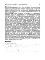
23
26
mmih 1 1 nun
27
30
/i/i/u\rv
MECHANICAL
MOVEMENTS.
23.
A contrivance
for
transmitting rotary
motion
to
a movable
pulley.
The
pulley
at
the bottom of the
figure
is the
movable
one
;
if
this
pulley
were
raised
or
depressed,
the belt
would be slackened
or
tightened
accordingly.
In
order
to
keep
a
uniform
tension
on the
belt,
a
pulley,
A,
carried
in
a
frame
sliding
between
guides
(not
shown),
hangs
from a
rope
passing
over the two
guide-pulleys,
B, B,
and
is
acted
upon
by
the
balance
weight,
C,
in such manner as to
produce
the desired result.
24.
Spur-gears.
25.
Bevel-gears.
Those of
equal
diame-
ters are termed
"
miter-gears."
26.
The wheel to
the
right
is
termed a
"
crown-wheel
;"
that
gearing
with
it is a
spur-gear.
These wheels
are
not
much
used,
and
are
only
available for
light
work,
as
the
teeth
of
the
crown-wheel
must
necessarily
be
thin.
27.
"
Multiple
gearing
"
a
recent
inven-
tion. The
smaller
triangular
wheel drives
the
larger
one
by
the
movement of its at-
tached friction-rollers
in the radial
grooves.
28.
These
are
sometimes called
"brush-
wheels."
The relative
speeds
can
be varied
by changing
the distance
of the
upper
wheel
from
the center
of the lower one. The
one
drives the other
by
the friction
or
adhesion,
and this
may
be
increased
by facing
the lower
one with
india-rubber.
29.
Transmission
of
rotary
motion
from
one
shaft at
right angles
to another.
The
spiral
thread of the disk-wheel drives the
spur-gear, moving
it the distance
of
one
tooth
at
every
revolution.
30.
Rectangular gears.
These
produce
a
rotary
motion
of the
driven
gear
at
a
varying
speed. They
were
used
on
a
printing-press,
the
type
of which were
placed
on a
rectangu-
lar
roller.
MECHANICAL
MOVEMENTS.
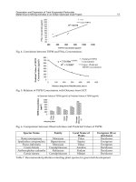
31 32
33
SO
P<0>-
SCO
MECHANICAL
MOVEMENTS.
31.
Worm or
endless screw and a
worm-
wheel.
This effects
the
same result as
29
;
and as
it is more
easily
constructed,
it is
oftener
used.
32.
Friction-wheels. The surfaces
of
these
wheels are
made
rough,
so
as to bite
as
much as
possible
;
one
is
sometimes faced
with
leather, or, better,
with
vulcanized
india-
rubber.
33. Elliptical
spur-gears.
These are used
where a
rotary
motion of
varying
speed
is
required,
and
the variation
of
speed
is
de-
termined
by
the relation between the
lengths
of the
major
and minor
axes of the
ellipses.
34.
An
internally
toothed
spur-gear
and
pinipn.
With
ordinary spur-gears
(such
as
represented
in
24)
the
direction
of
rotation is
opposite
;
but
with
the
internally
toothed
gear,
the two
rotate
in
the same direction
;
and with the same
strength
of
tooth the
gears
are
capable
of
transmitting
greater
force,
because more teeth are
engaged.
35.
Variable
rotary
motion
produced
by
uniform
rotary
motion.
The small
spur-
pinion
works in a slot
cut
in
the
bar,
which
turns
loosely
upon
the shaft of the
elliptical
gear.
The
bearing
of the
pinion-shaft
has
applied
to it
a
spring,
which
keeps
it
en-
gaged
;
the
slot in
the
bar is to allow for
the
variation of
length
of radius of
the
elliptical
gear.
36.
Mangle-wheel
and
pinion
so
called
from
their
application
to
mangles
converts
continuous
rotary
motion of
pinion
into
re-
ciprocating
rotary
motion
of
wheel.
The
shaft of
pinion
has
a
vibratory
motion,
and
works in
a
straight
slot cut
in
the
upright
!
stationary
bar to allow
the
pinion
to rise
and
fall and work
inside and outside of the
gear-
ing
of
the wheel. The slot cut
in
the face
of
I
the
mangle-wheel
and
following
its outline
is
to
receive and
guide
the
pinion-shaft
and
keep
the
pinion
in
gear.
37.
Uniform into
variable
rotary
motion.
The
bevel-wheel or
pinion
to the left has
teeth cut
through
the whole
width of
its face.
Its teeth work with a
spirally
arranged
series
of studs on a
conical wheel.
38.
A means of
converting
rotary
motion,
by
which the
speed
is
made uniform
during
a
part,
and varied
during
another
part,
of
the
revolution.
39. Sun-and-planet
motion. The
spur-
gear
to
the
right,
called the
planet-gear,
is
tied to the center of the
other,
or
sun-gear,
by
an arm which
preserves
a constant dis-
tance between
their
centers.
This was
used
as a substitute for
the
crank
in
a
steam
en-
gine by
James
Watt,
after the use
of
the
crank had
been
patented
by
another
party.
Each revolution of the
planet-gear,
which
is
rigidly
attached to the
connecting-rod, gives
two to the
sun-gear,
which
is
keyed
to
the
fly-wheel
shaft.
i6
MECHANICAL
MOVEMENTS.
40
MECHANICAL
MOVEMENTS.
40
and
41.
Rotary
converted
into
rotary
of the
spring
as it uncoils itself. The chain
motion.
The
teeth
of
these
gears,
being
is
on the
small diameter
of the
fusee when
oblique, give
a
more
continuous
bearing
the watch
is wound
up,
as the
spring
has
than
ordinary
spur
gears.
then
the
greatest
force.
42
and
43.
Different
kinds
of
gears
for
transmitting
rotary
motion
from one
haft
to another
arranged
obliquely
thereto.
44.
A kind of
gearing
used
to
transmit
great
force
and
give
a continuous
bearing
to
the teeth. Each,
wheel
is
composed
of
two,
three,
or more
distinct
spur-gears.
The
teeth,
instead
of
being
in
line,
are
arranged
in
steps
to
give
a
continuous
bearing.
This
system
is sometimes used
for
driving
screw
propellers,
and
sometimes,
with
a
rack of
similar
character,
to drive the
beds
of
large
iron-planing
machines.
45.
Frictional
grooved
gearing
a com-
paratively
recent invention.
The
diagram
to the
right
is an
enlarged
section,
which
can
be more
easily
understood.
46.
Fusee chain and
spring-box,
being
the
prime
mover
in
some
watches,
particu-
larly
of
English
make. The fusee to the
right
is to
compensate
for the loss of force
47.
A
frictional
clutch-box,
thrown
in and
out
of
gear by
the lever
at the
bottom.
i
This is used for
connecting
and
discon-
necting heavy machinery.
The
eye
of the
disk to the
right
has a slot which
slides
upon
a
long key
or feather
fixed on the
shaft.
48.
Clutch-box. The
pinion
at the
top
gives
a continuous
rotary
motion to
the
gear
below,
to
which
is attached
half the
clutch,
and both turn
loosely
on the
shaft. When
it is
desired to
give
motion to the
shaft,
the
other
part
of the
clutch,
which
slides
upon
a
key
or feather
fixed
in
the
shaft,
is
thrust
into
gear
by
the lever.
49.
Alternate
circular
motion
of
the hori-
zontal shaft
produces
a
continuous
rotary
motion
of the vertical
shaft,
by
means of
the ratchet-wheels secured to the
bevel-
gears,
the ratchet-teeth of
the two
wheels
being
set
opposite
ways,
and the
pawls
act-
ing
in
opposite
directions. The
bevel-gears
and
ratchet-wheels are loose
on
the
shaft,
and.
the
pawls
attached to arms
firmly
se-
cured on
the
shaft.
i8 MECHANICAL
MOVEMENTS.