Aluminium Design and Construction - Chapter 9 docx
Bạn đang xem bản rút gọn của tài liệu. Xem và tải ngay bản đầy đủ của tài liệu tại đây (512.17 KB, 26 trang )
CHAPTER 9
Tension and compression
members
9.1 GENERAL APPROACH
9.1.1 Modes of failure
This chapter covers the static design of members subjected to axial
force either in tension (‘ties’) or in compression (‘struts’). The basic
requirement is that the factored resistance should not be less than the
tensile or compressive force (action-effect) arising in the member under
factored loading. The factored resistance is found by dividing the calculated
resistance by the factor
m
(Section 5.1.3). There are four possible modes
of failure to consider in checking such members:
1. localized failure of the cross-section (Section 9.3);
2. general yielding along the length (Section 9.4);
3. overall column buckling (Section 9.5);
4. overall torsional buckling (Section 9.6).
Check 1, which applies to both ties and struts, must be satisfied at any
cross-section in the member. It is likely to become critical when a particular
cross-section is weakened by HAZ softening or holes. Checks 2, 3 and
4 relate to the overall performance of the entire member. Check 2 is
made for tension members, and checks 3 and 4 for compression members.
Check 4 is not needed for hollow box or tubular sections.
Most of the chapter is concerned with finding the calculated resistance
P
c
to each mode of failure, when the force on the member acts
concentrically, i.e. through the centroid of the cross-section. We then go
on to consider the case of members which have to carry simultaneous
axial load and bending moment (Section 9.7), one example of this being
when an axial load is applied eccentrically (not through the centroid).
Copyright 1999 by Taylor & Francis Group. All Rights Reserved.
9.1.2 Classification of the cross-section (compression members)
An early step in the checking of a compression member is to classify
the section as compact or slender. If it is compact, local buckling is not
a factor and can be ignored. If it is slender, local buckling will reduce
the strength and must be allowed for.
The classification procedure is first to classify the individual plate
elements comprising the section, by comparing their slenderness ß with
the limiting value ß
s
(Section 7.1.4). The classification for the section as
a whole is then taken as that for the least favourable element. Thus for
a section to be compact, all its elements must be compact. If one element
is slender, then the overall cross-section is slender.
Refer to Chapter 7 for the definition of the plate slenderness ß (Section
7.1.3 or 7.4.5), and also for the determination of ß
s
(Table 7.1).
9.2 EFFECTIVE SECTION
9.2.1 General idea
It is important to consider three possible effects which may cause local
weakening in a member, namely HAZ softening at welds, buckling of thin
plate elements in compression and the presence of holes. These are allowed
for in design by replacing the actual cross-section with a reduced or effective
one (of area A
e
) which is then assumed to operate at full strength.
Reference should be made to Chapter 6 in dealing with HAZ softening,
and Chapter 7 for local buckling. Chapter 10 gives advice on the
determination of section properties.
9.2.2 Allowance for HAZ softening
Referring to Chapter 6, we assume that at any welded joint there is a
uniformly weakened zone (HAZ) of nominal area A
z
, beyond which a
step-change occurs to full parent properties. We take an effective thickness
of k
z
t in this zone and calculate A
e
accordingly, with the softening factor
k
z
put equal to k
z1
or k
z2
depending on the type of resistance calculation
being performed:
Local failure of the cross-section k
z
=k
z1
General yielding k
z
=k
z2
Overall buckling k
z
=k
z2
Alternatively a ‘lost area’ of A
z
(1-k
z
) can be assumed at each HAZ,
which is then deducted from the section area. This procedure is often
preferable at a cross-section just containing small longitudinal welds,
as it avoids the need to find the actual disposition of the HAZ material,
A
z
for such welds being a simple function of the weld size (Section
Copyright 1999 by Taylor & Francis Group. All Rights Reserved.
6.5.6). The first method becomes necessary when there are transverse
welds, and for bigger welds generally.
Care must be taken in dealing with a plate where the HAZ does not
penetrate all the way through the thickness (Figure 6.16). The factor k
z
need only be applied to the softened part of the thickness in such a case.
9.2.3 Allowance for local buckling
When a column cross-section has been classed as slender, the effective
section of any slender element in it is assumed to be of the form shown
in Figure 7.4 (internal elements) or Figure 7.5 (outstands), using an effective
width model. The determination of the effective block-width (b
e1
or b
e0
)
is explained in Sections 7.2.3 and 7.2.4, or in Section 7.4.7 for reinforced
elements. Very slender outstands need special consideration (Section 9.5.4).
9.2.4 Allowance for holes
At any given cross-section, holes are generally allowed for by deducting
an amount dt per hole, where d is the hole diameter and t the plate
thickness. Exceptions are as follows:
1. For a hole in HAZ material, the deduction per hole need only be k
z
dt.
2. Filled holes can be ignored in compression members.
3. A hole in the ineffective region of a slender plate element in a
compression member can be ignored.
When a group of holes in a member is arranged in a staggered pattern,
as for example in the end connection to a tension member, there are
various possible paths along which tensile failure of the member might
occur and it may not be obvious which is critical. Thus in Figure 9.1(a) the
member might simply fail in mode A on a straight path through the first
Figure 9.1 Staggered holes in tension members.
Copyright 1999 by Taylor & Francis Group. All Rights Reserved.
hole. Alternatively, it might fail in mode B or C, involving a crooked
failure path with diagonal portions in it. Similarly in Figure 9.1(b). In
such cases, the effective area A
e
must be found for each possible failure
path, and the lowest value taken. In considering a crooked failure path,
A
e
can be estimated as follows:
(9.1)
where A=total transverse section area, n=number of holes on the failure
path, and x, y=longitudinal and transverse hole pitch, as shown. The
summation is made for every diagonal portion of the failure path between
pairs of holes.
9.3 LOCALIZED FAILURE OF THE CROSS-SECTION
The calculated resistance P
c
of an axially loaded member to localized
failure at a specific cross-section is found thus:
P
c
=A
e
P
a
(9.2)
where p
a
=limiting stress for the material (Section 5.3), and A
e
=effective
section area.
The use of the higher limiting stress p
a
, rather than the usual value
p
o
, reflects the view that some limited yielding at a localized cross-
section need not be regarded as representing failure of the member.
The effective area A
e
should be based on the most unfavourable position
along the member, making suitable allowance for HAZ softening, local
buckling (compression only) or holes as necessary (Section 9.2). When
considering the local buckling of a very slender outstand, it is permissible
to take advantage of post-buckled strength for this check (Section 7.2.5).
In the case of hybrid members containing different strength materials,
P
c
should be found by summing the resistances of the various parts,
taking an appropriate p
a
for each.
9.4 GENERAL YIELDING ALONG THE LENGTH
This is the form of failure in which the member yields all along its length,
or along a substantial part thereof. It need only be checked specifically
for tension members, because the column buckling check automatically
covers it in the case of struts. The calculated resistance P
c
is obtained thus:
P
c
=A
e
P
o
(9.3)
where p
o
=limiting stress for the material (Section 5.3), and A
e
=effective
section area.
Copyright 1999 by Taylor & Francis Group. All Rights Reserved.
One difference from the treatment of localized failure is the use of
the limiting stress p
o
, rather than the higher value p
a
. For most materials,
p
o
is taken equal to the 0.2% proof stress.
The other difference is that the effective area A
e
now relates to the
general cross-section of the member along its length, ignoring any
localized weakening at the end connections or where attachments are
made. For a simple extruded member, therefore, A
e
may be taken equal
to the gross area A. Holes need only be allowed for if there is a
considerable number of these along the member. Likewise, a deduction
for HAZ softening is only necessary when the member contains welding
on a significant proportion of its length.
9.5 COLUMN BUCKLING
9.5.1 Basic calculation
Column (or flexural) buckling of a strut is the well-known mode of
failure in which the central part of the member ‘pops out sideways’.
The calculated resistance P
c
is given by:
P
c
=Ap
b
(9.4)
where p
b
=column buckling stress, and A=gross section area.
This equation should be employed to check for possible buckling
about each principal axis of the section in turn. For a built-up member,
consisting of two or more components connected together at intervals
along the length, buckling should be checked not only for the section
as a whole (about either axis), but also for the individual components
between points of interconnection. For back-to-back angles, such that
the buckling length is the same about both principal axes, accepted
practice is to interconnect at third-points.
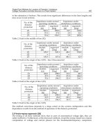
9.5.2 Column buckling stress
The buckling stress p
b
depends on the overall slenderness . It may be
read from one of the families of curves (C1, C2, C3) given in Figure 9.2,
the derivation of which was explained in Chapter 5. Alternatively, it
may be calculated from the relevant formula (Section 5.4.2).
The appropriate family, which need not necessarily be the same for
both axes of buckling, is chosen as follows:
The terms ‘symmetric’ and ‘asymmetric’ refer to symmetry about the
axis of buckling. A severely asymmetric section is one for which y
1
Copyright 1999 by Taylor & Francis Group. All Rights Reserved.
Figure 9.2 Limiting stress p
b
for column buckling.
Copyright 1999 by Taylor & Francis Group. All Rights Reserved.
exceeds 1.5y
2
, where y
1
and y
2
are the distances from this axis to the
further and nearer extreme fibres. For family selection, a strut is regarded
as ‘welded’ if it contains welding on a total length greater than the
largest dimension of the section.
The different curves in each family are defined by the stress p
1
at
which they meet the stress axis. Having selected the right family, the
appropriate curve in that family is found by taking p
1
as follows:
(9.5)
where p
o
=limiting stress for the material (Section 5.3), A=gross section
area, and A
e
=effective section area (Section 9.2).
A
e
relates to the basic cross-section, with weakening at end connections
ignored. For a compact extruded member, A
e
=A and p
1
=p
o
.
In finding p
1
for a welded strut, HAZ effects must generally be allowed
for, even when the welding occupies only a small part of the total
length. They can only be ignored when confined to the very ends. It is
seen that welded struts are doubly penalized: firstly, in the use of a less
favourable family and, secondly in the adoption of an inferior curve in
that family (lower p
1
). No deduction for unfilled holes need be made in
the overall buckling check, unless they occur frequently along the length.
9.5.3 Column buckling slenderness
The slenderness parameter needed for entering the column buckling
curve (C1, C2 or C3) is given by:
(9.6)
where l=effective buckling length, and r=radius of gyration about the
relevant principal axis, generally based on the gross section.
Figure 9.3 Column buckling, effective length factor K.
Copyright 1999 by Taylor & Francis Group. All Rights Reserved.
The determination of l involves a considerable degree of judgment
(i.e. guesswork) by the designer—as in steel. It is found as follows:
l=KL (9.7)
where L=unsupported buckling length, appropriate to the direction of
buckling. K may be estimated with the help of Figure 9.3.
9.5.4 Column buckling of struts containing very slender outstands
For a column containing very slender outstands (Section 7.2.5), the designer
must know whether it is permissible to assume an effective section that
takes account of the post-buckled strength of these. There are two possible
procedures:
1. Method A is effectively the same as that given in BS.8118. p
1
(expression
(9.5)) is based on an effective section that ignores post-buckled strength
in such elements, using expression (7.8) to obtain
o
. But in finding
, it bases r on the gross section. It is further assumed that the member
is under pure compression (no bending) when the applied load aligns
with the centroid of the gross section.
2. Method B employs an effective section which takes advantage of
post-buckled strength in very slender elements, with
o
found from
expression (7.7). This effective section is employed for obtaining both
A
e
and r. The member now counts as being in pure compression
when the applied load acts through the centroid of the effective section.
Method B thus employs a higher buckling curve (higher p
1
), but enters
it at a higher . Method A is found to be the more favourable for the
majority of cases, but method B becomes advantageous if the member
is short (low ).
9.6 TORSIONAL BUCKLING
9.6.1 General description
There are three fundamental modes of overall buckling for an axially
loaded strut [27]:
1. column (i.e. flexural) buckling about the minor principal axis;
2. column buckling about the major axis;
3. pure torsional buckling about the shear centre S.
Figure 9.4 shows the mid-length deflection corresponding to each of
these for a typical member. The mode with the lowest failure load is the
one that the member would choose.
Torsion needs to be considered for open (non-hollow) sections. Because
the torsional stiffness of these is roughly proportional to thickness cubed,
Copyright 1999 by Taylor & Francis Group. All Rights Reserved.
the torsional mode never governs when the section is thick, as in heavy
gauge (hot-rolled) steel. It becomes more likely as the thickness decreases,
and for thin-walled members it is often critical, as also in light gauge
(cold-formed) steel. The checking of torsional buckling tends to be
laborious. Here we follow the treatment given in BS.8118, which is
more comprehensive than any provided in previous codes. The calculations
involve the use of torsional section properties, which may not be familiar
to some designers. Chapter 10 provides help for evaluating these.
9.6.2 Interaction with flexure
A tiresome complication with torsional buckling is that the fundamental
buckling modes often interact, depending on the degree of symmetry
in the section (Figure 9.5):
1. Bisymmetric section. The three modes are independent (no interaction);
2. Radial-symmetric section. As for 1;
3. Skew-symmetric section. As for 1;
4. Monosymmetric section. Interaction occurs between pure torsional
buckling about the shear centre S and column buckling about the
axis of symmetry ss;
5. Asymmetric section. All three modes interact.
The effect of interaction is to make the section rotate about a point other
than the shear centre S, as illustrated for a monosymmetric section in
Figure 9.4 Fundamental buckling modes for a compression member.
Figure 9.5 Degrees of symmetry for strut sections: (1) bisymmetric; (2) radial-symmetric;
(3) skew-symmetric; (4) monosymmetric; (5) asymmetric.
Copyright 1999 by Taylor & Francis Group. All Rights Reserved.
Figure 9.6, and leading to a reduced failure load. Strictly speaking,
interaction between torsional and column buckling can occur very slightly
even with thick members. But the effect only becomes significant when
the section is thin.
9.6.3 ‘Type-R’ sections
In dealing with torsional buckling it is important to distinguish between
‘type-R’ sections and all others. A type-R section is one that consists
entirely of radiating outstands, such as angles, tees and cruciforms (Figure
9.7). For such members, each component element is simply supported
along the common junction, or nearly so. When such an element suffers
local buckling, it typically does so in one sweep occupying the whole
length of the member (Figure 9.8), and not in a localized buckle as for
other thin-walled shapes. This is essentially a torsional mode of
deformation, In thin type-R sections, therefore, local buckling and torsional
buckling amount to much the same thing.
In design, it is convenient to treat the buckling of type-R struts in
terms of torsion, rather than local buckling. By so doing, one is able to
take advantage of the rotational restraint that the outstands may receive
from the fillet material at the root. Double-angle (back-to-back) struts
can also be regarded as effectively type-R.
9.6.4 Sections exempt from torsional buckling
Torsional buckling is never critical for a strut with any of the sections
listed below, and need not be checked:
Figure 9.6 Monosymmetric section. Interaction between pure flexural buckling about ss
and pure torsional buckling about S.
Figure 9.7 Typical ‘type-R’ sections, composed of radiating outstands.
Copyright 1999 by Taylor & Francis Group. All Rights Reserved.
1. Box or tubular sections (always much stiffer in torsion than a
comparable open section);
2. Any type-R section that would be classified as compact for local
buckling;
3. Conventional bisymmetric I-sections (with unreinforced flanges);
4. Conventional skew-symmetric Z-sections (with unreinforced flanges).
9.6.5 Basic calculation
As with column buckling, the basic expression for the calculated resistance
P
c
is as follows:
P
c
=Ap
b
(9.8)
where p
b
is now the torsional buckling stress, allowing for interaction
with flexure if necessary, and A is the gross section area as before.
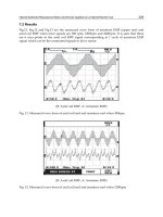
9.6.6 Torsional buckling stress
The buckling stress p
b
depends on the torsional buckling slenderness
parameter and may be read from one of the families of curves (T1,
T2) given in Figure 9.9. Alternatively, it may be calculated from the
relevant formula (Section 5.4.2). The appropriate family is chosen as
follows, the T2 curves being the more favourable:
Type-R sections T2
All other sections T1
Figure 9.8 Torsional buckling of a type-R section strut.
Copyright 1999 by Taylor & Francis Group. All Rights Reserved.
The different curves in each family are defined by the stress p
1
at which
they cut the stress axis, the relevant curve being found by taking p
1
as
follows:
(9.9)
where p
o
=limiting stress for the material (Section 5.3), A=gross section
area, and A
e
=effective area of the cross-section, disregarding any localized
weakening at the end-connections.
1. Type-R sections. A
e
is found by making a suitable reduction to allow
for any HAZ softening. No reduction is made for local buckling. Thus
for an unwelded Type-R section A
e
=A even if its section is not compact.
2. Other sections. For these A
e
is found in the same way as for column
buckling, making suitable reductions to allow for both HAZ softening
and local buckling. For a simple extruded member of compact section,
A
e
=A.
Figure 9.9 Limiting stress p
b
for torsional buckling.
Copyright 1999 by Taylor & Francis Group. All Rights Reserved.
9.6.7 Torsional buckling slenderness
The following is the rigorous procedure for obtaining the slenderness
parameter needed for entering the selected buckling curve. An alternative
and quicker method, available for certain common shapes, involves the use
of empirical formulae (Section 9.6.10). Under the rigorous procedure we take:
=k
t
(9.10)
where
t
=slenderness parameter based on pure torsional buckling about
the shear centre S, and k=torsion/flexure interaction factor (Section 9.6.8).
The slenderness parameter
t
may be determined using the following
general expression, which is valid for aluminium:
(9.11)
where =St Venant torsion factor, I
p
=polar inertia about shear centre S,
H=warping factor, and l=effective buckling length.
Here , Ip and H may be based on the gross section, and can be
found with the aid of Chapter 10. The effective length l is less critical
than with column buckling, and is normally taken equal to the actual
buckling length L. A lower value may be justified if there is significant
warping restraint at the ends, but not if the ends are welded.
The warping factor H for type-R sections is always zero, or virtually
so. It is therefore seen from the previous equation that
t
for these is
independent of length and becomes:
(9.12)
The torsional stability of type-R sections can be much improved by
providing liberal bulb and/or fillet material, since this increases .
Fillet size is less important for non-R shapes, because these have warping
resistance to improve their stability.
9.6.8 Interaction factor
The interaction factor k depends on the symmetry of the section (Figure
9.5) and should be found as follows, using the gross section in every case:
1. Bisymmetric sections. k=1
2. Radial-symmetric sections. k=1
3. Skew-symmetric sections. k=1
4. Mono-symmetric sections, k can be read from Figure 9.10 or else calculated
from the corresponding formula:
(9.13)
Copyright 1999 by Taylor & Francis Group. All Rights Reserved.
where s=
s
/
t
s
=slenderness parameter for column buckling about the axis of
symmetry ss,
X=(I
ss
+I
yy
)/I
p
I
ss
, I
yy
=inertias about the axis of symmetry and about the other
principal axis, respectively.
5. Asymmetric sections. When the section has no symmetry, so that all
three fundamental modes interact, k should be calculated as follows:
(9.14)
where
U, V=coordinates of shear-centre S (Figure 10.20),
I
uu
, I
vv
=major and minor principal axis inertias,
v
=minor axis column buckling slenderness,
t
=pure torsional buckling slenderness (equation (9.11)).
The quantity x is the lowest root of the following cubic, for the solution
of which BS.8118 provides a convenient nomogram:
x
3
-3x
2+
Ax-B=0 (9.15)
where
9.6.9 Torsional buckling of struts containing very slender outstands
When the section contains very slender outstands (Section 7.2.5), the
question arises as to how to handle the local buckling thereof. Which
effective section should be assumed: one that exploits the post-buckled
strength of such elements, or one that ignores it? As with column buckling
there are two possible options:
1. Method A is that adopted in BS.8118. p
1
is based on an effective section
that ignores the post-buckled strength of very slender outstands. But
in finding , it bases
t
and k on the gross section.
Copyright 1999 by Taylor & Francis Group. All Rights Reserved.
2. Method B employs an effective section which takes advantage of the
post-buckled strength of these elements, this effective section being
used for the determination of p
1
In finding , the method bases
s
or
v
on the same effective section, but all the other quantities are based
on the gross section.
As with column buckling, method B tends to be more favourable than
method A at low .
9.6.10 Empirical slenderness formulae
The torsional buckling slenderness parameter may be obtained
more simply for some conventional sections by using empirical
formulae. These are taken from BS.8118 and relate to the shapes
shown in Figures 9.11 and 9.13. The slenderness is still found from
the basic expression (9.10), but with
t
now calculated using the
appropriate data in Table 9.1 or 9.2. As before, k is read from Figure
9.10. Note that the formulae in the two tables will be inaccurate if
used outside the ranges indicated.
1. Type-R sections. Figure 9.11 shows the shapes covered and the notation,
the required formulae for
t
being given in Table 9.1. The parameter
in these is a measure of the fillet reinforcement defined as follows
(Figure 9.12):
Figure 9.10 Torsional buckling of monosymmetric sections, interaction factor k.
Copyright 1999 by Taylor & Francis Group. All Rights Reserved.
Figure 9.13 Sections covered in Table 9.2.
Figure 9.12 Root reinforcement.
Figure 9.11 Type-R sections covered in Table 9.1.
Copyright 1999 by Taylor & Francis Group. All Rights Reserved.
Table 9.1 Torsional buckling of certain type-R sections—empirical formulae for
t
and X
Notes. 1. Refer to Figure 9.11 for section details.
2. Despite the asymmetry of sections SA3 and SA4 the interaction factor k is still found accurately
enough using Figure 9.10. In entering this we take s=(
u
/
t
) {1+6(1-B/D)
2
}, where
u
is the
slenderness for column buckling about the major principal axis.
Table 9.2 Torsional of certain channel-type sections—empirical formulae for
, , X
Note. Refer to Figure 9.13 for section details.
Copyright 1999 by Taylor & Francis Group. All Rights Reserved.
The value of X, needed to obtain k, may be calculated using the
relevant formula in Table 9.1. s is taken as in Section 9.6.8(4), except
in the case of the unequal angles SA3 and SA4.
2. Channel and top-hat sections. The shapes covered and the notation, are
shown in Figure 9.13. For all of these
t
is calculated from the general
expression:
(9.16)
Figure 9.14 Four standardized profiles (BS. 1161).
Table 9.3 Properties of certain standardized shapes
Notes. 1. The sections are standardized in BS 1161.
2. For section details refer to Figure 9.14.
Copyright 1999 by Taylor & Francis Group. All Rights Reserved.
where
s
=slenderness parameter for column buckling about ss, and
, =parameters to be calculated using the relevant formulae in Table
9.2. Simple values are given for X.
9.6.11 Torsional buckling of certain standardized sections
Figure 9.14 shows four section shapes that are standardized in Britain
(BS.1161), having been proposed in 1952 by M.Bridgewater and J.B.
Dwight (except for the tee), as efficient profiles with a good compromise
between flexural, torsional and local stability. Each comes in a range of
geometrically similar sizes, and Table 9.3 lists their section properties
(in terms of the thickness t).
Table 9.4 lists seven different shapes of strut section using these
profiles, for which the torsional buckling slenderness can be readily
determined from expression (9.10), with
t
read direct from the table,
while k is found as in 9.6.8(4) using X and s as listed in the table.
9.7 COMBINED AXIAL FORCE AND MOMENT
9.7.1 The problem
When a member has to carry simultaneous axial force P and moment
M, it is obviously important to allow for interaction between the two,
typical examples being eccentrically loaded axial members and ‘beam-
columns’. Below we provide checks that cover failure of the cross-section
and overall buckling of the member. A simplified procedure is available
for checking simple angles, channels and tees connected to one side of
a gusset (Section 9.7.9).
Table 9.4 Torsional buckling of certain standardized profiles: parameter values
Notes. 1. Refer to Figure 9.14 for section geometry.
2. Despite its asymmetry, the value of k for section S2 may be found accurately enough as in
Section 9.6.8(4) taking s as given above.
3. For the back-to-back angles it is assumed that the two components are separated by a distance
t (at least).
4. For the channel S4:
Copyright 1999 by Taylor & Francis Group. All Rights Reserved.
9.7.2 Secondary bending in trusses
The members in triangulated truss-type structures, although primarily
subject to axial force, also pick up bending moments at their ends due
to joint rigidity. These ‘secondary’ moments can be significant and the
question arises as to whether to allow for them in design.
Linear elastic analysis readily enables secondary truss moments to
be computed, but the answer obtained is only valid in the early stages
of loading. When buckling is imminent, the moments at the ends of a
critical member are found to decrease and eventually change sign,
changing from disturbing moments to restraining ones. The normal
approach for obtaining the calculated static resistance of a truss member
is therefore to ignore secondary bending and just consider the axial
force. The situation is different in doing a fatigue check, when the
secondary bending stresses must be included.
The exception is when there is a significant non-concurrence of the
centroidal lines at a node, in which case the resulting eccentricity of
loading must always be considered, treated as a case of combined P
and M. Normally it is desirable to detail the truss so as to achieve
concurrence of the centroidal lines based on the gross section. However,
for thin channel-type members with very slender flange elements this
is not necessarily valid (Section 9.5.4).
9.7.3 Section classification
As in pure bending, the section must first be classified as fully-compact,
semi-compact or slender, unless it is in tension all over. Note that a
single classification is needed, corresponding to the particular combination
of P and M being applied. Again this is obtained by classifying any
individual elements that are wholly or partly in compression, the least
favourable element then dictating the classification for the section as a
whole.
In considering an element under strain gradient (Section 7.3), the
parameter
should be based on the usual assumption of flexural
behaviour (‘plane sections remain plane’). In other words, we put
=y
2
/
y
1
where y
1
and y
2
are the distances of the more heavily compressed
edge and the other edge from the neutral axis. The assumed neutral
axis should be that corresponding to the simultaneous action of P and
M, using a plastic stress pattern for the fully-compact or an elastic one
for the semi-compact check (Figure 9.15). In either case it is acceptable,
for classification purposes, to take this as the axis based on the gross
section. When P is high, it is possible for the elastic neutral axis to lie
outside the section.
In making the semi-compact check, it is permissible with an
‘understressed’ compression flange to use the same kind of relaxation as
Copyright 1999 by Taylor & Francis Group. All Rights Reserved.
that employed in the pure bending case (Section 8.2.8). This consists of
replacing in Table 7.1 by a modified value ’ given by:
(9.17)
where y
c
=distance from the elastic neutral axis to the element considered,
and y
0
=distance from the same axis to the far extreme fibres.
The assumed neutral axis, which again is based on the gross section,
should relate to the combined action of P and M.
9.7.4 Interaction formulae (P+uniaxial M)
Below we give four checks (A–D) that apply to members subject to
axial load P (applied at the centroid) and moment M, when the axis of
M either coincides with an axis of symmetry of the section or is
perpendicular to such an axis (Figure 9.16). Table 9.5 indicates which
checks are needed for different loading cases.
The checks appear in the form of interaction formulae and are based
on BS.8118. They give permissible combinations of P and M, the sign
convention being such that every term in each expression is positive.
The following general notation is used:
P=axial force arising under factored loading;
M=moment arising at a given cross-section under factored
loading;
Figure 9.15 Combined axial load and moment, idealized stress patterns: (a) plastic; (b)
elastic. NA=neutral axes.
Figure 9.16 Axial load with uniaxial moment.
Copyright 1999 by Taylor & Francis Group. All Rights Reserved.
M
–
=equivalent uniform value of M, found as in Section 8.7.3;
P
c
=calculated resistance to axial load (on its own);
M
c
=calculated resistance to moment (on its own).
Check A: Localized failure of the cross-section
(9.18)
where: P
c
=value found as in Section 9.3 based on p
a
M
c
=value found as in Section 8.2, reduced to allow for shear.
Check B: General yielding along the length
(9.19)
where: P
c
=value found as in Section 9.4 based on p
o
M
c
=as for check A, but with no reduction for shear.
Check C: Overall buckling in the plane of the moment
(9.20)
where: P
c
=resistance to overall column buckling in the plane of the
moment or to torsional buckling,
M
c
=as for check A, but with no reduction for shear.
Check D: Overall buckling out of the plane of the moment
(9.21)
where: P
c
=resistance to column buckling about other axis,
S=plastic modulus of gross section about axis of M,
p
b
=limiting stress for LT buckling (Section 8.7.4).
Table 9.5 Necessary checks for members under combined axial load (P) and moment (M)
Copyright 1999 by Taylor & Francis Group. All Rights Reserved.
Note that when P is tensile, the first term in equation (9.21) should
be put equal to zero. Also, if the section is of a type not prone to LT
buckling, p
b
is put equal to M
C
/S where M
c
is as in check B.
9.7.5 Alternative treatment (P+uniaxial M)
The checks A and B tend to be oversafe when applied to fully-compact
profiles, and for these a more realistic result can be obtained by using
a direct plastic calculation instead:
(9.22a)
(9.22b)
where p
o
is the limiting material stress for bending (Section 5.3), and S
p
is a suitably reduced value for the plastic modulus that allows for the
presence of P (Section 10.2.3). S
p
is different for the two checks.
Figure 9.17 compares results thus obtained with those given by the
British Standard rule. It covers check A for a fully-compact box section,
and shows how the reduced moment resistance of the section (in the
presence of axial load) varies with P. It is seen that the British Standard
rule can underestimate by as much as 20%.
9.7.6 Interaction formulae (P+biaxial M)
We now consider the case when the applied moment acts about an axis
mm inclined at to the major principal axis xx (Figure 9.18). Section
classification follows the same principles as those given in Section 9.7.3,
a single classification being needed which corresponds to the particular
Figure 9.17 Reduced moment resistance of a fully-compact square box cross-section in
the presence of axial load: (1) BS 8118 rule (equation 9.18); (2) Direct plastic calculation
(equation (9.22a)).
Copyright 1999 by Taylor & Francis Group. All Rights Reserved.
combination of P and M being considered.The relevant checks (E–G)
are given below (refer to Table 9.5). P, M and M
–
and the sign convention
are the same as in Section 9.7.4.
Check E: Localized failure of the cross-section
(9.23)
where: P
c
=value found as in Section 9.3 based on p
a
M
cx
, M
cy
=resistance of cross-section to bending about xx and yy,
reduced to allow for shear.
Check F: General yielding along the length
(9.24)
where: P
c
=value found as in Section 9.4 based on p
o
M
cx
, M
cy
=as for check A, but with no reduction for shear.
Check G: Overall buckling
(9.25)
where: M
–
cpx
=permissible value of M
–
acting about Gx taken as the lower
of the values given by (9.20) and (9.21)
M
–
cpy
=permissible value of M
–
acting about Gy given by (9.20).
The above interaction formulae may also be applied to a skew-symmetric
section, if x and y are changed to u, v.
9.7.7 Alternative treatment (P+biaxial M)
The checks E and F sometimes prove unduly pessimistic, in which case
better economy may be obtained by using alternative procedures as follows:
Figure 9.18 Axial load with biaxial moment.
Copyright 1999 by Taylor & Francis Group. All Rights Reserved.
1. Fully-compact sections. The limiting values of moment for the two
checks are found by employing the plastic expressions (9.22) with S
p
changed to S
pm
. Here S
pm
is a modified value of the plastic modulus,
which takes account of the inclination of mm as well as the presence
of P (Section 10.2.3).
2. Semi-compact and slender sections. The applied moment is resolved
into components M cos and M sin about the principal axes, the
effects of which are superposed elastically with that of P. The section
is adequate if at any critical point Q:
(9.26a)
(9.26b)
where x, y are the coordinates of Q, and the I’s relate to the effective
section. P is taken positive if tensile and negative if compressive. The
left-hand side of the equation is always taken positive.
9.7.8 Treatment of local buckling
In applying checks A–D and E–G, care is needed in dealing with
elements prone to local buckling. It was explained that the section
classification is based on the simultaneous action of P and M (Section
9.7.3). If on this basis the section comes out as fully or semi-
compact, no deduction for local buckling should be made in the
determination of P
c
and M
c
for these checks, even though the section
might be regarded as slender under the action of P or M in isolation.
But if (under P+M) the section is found to be slender, P
c
and M
c
should be found exactly as specified in Sections 9.7.4 and 9.7.6,
taking (different) effective sections each appropriate to the action
considered (P or M).
9.7.9 Eccentrically connected angles, channels and tees
Axial members of angle, channel or tee-section are often connected to
one side of a gusset-plate at their ends. Such members are subject to
end moment as well as axial force, because of the eccentricity of loading,
and may be rigorously checked using the appropriate interaction
equations. Alternatively, an easier method can be adopted as follows
without too severe loss of accuracy (based on BS.8118). The procedure
is to treat the member as an ordinary tie or strut, and make a simple
correction to allow for the eccentricity as follows:
Copyright 1999 by Taylor & Francis Group. All Rights Reserved.