ASME B31.3 docx
Bạn đang xem bản rút gọn của tài liệu. Xem và tải ngay bản đầy đủ của tài liệu tại đây (785.75 KB, 54 trang )
Table of Contents
Subject Index
Search
CASTI Guidebook
Process Piping
ASME B31.3
2nd Edition on CD-ROM
™
CASTI Publishing Inc.
10566 - 114 Street
Edmonton, Alberta T5H 3J7 Canada
Tel:(780) 424-2552 Fax:(780) 421-1308
E-Mail:
Internet Web Site: www.casti.ca
C
CASTI
CASTI Guidebook Series™
Volume 3
ASME B31.3
Process Piping
(Covering the 1999 Code Edition)
2nd Edition
Glynn E. Woods, P.E.
Roy B. Baguley, P.Eng.
Executive Editor
John E. Bringas, P.Eng.
Published By:
CASTI Publishing Inc.
10566-114Street
Edmonton, Alberta, T5H 3J7, Canada
Tel: (780) 424-2552 Fax: (780) 421-1308
E-mail:
Internet Web Site:
ISBN 1-894038-32-0
Printed in Canada
iii
CASTI Guidebook to B31.3 - Process Piping - 2nd Edition
CASTI PUBLICATIONS
CASTI GUIDEBOOK SERIES™
Volume 1 - CASTI Guidebook to ASME Section II - Materials Index
Volume 2 - CASTI Guidebook to ASME Section IX - Welding Qualifications
Volume 3 - CASTI Guidebook to ASME B31.3 - Process Piping
Volume 4 - CASTI Guidebook to ASME Section VIII Div. 1 - Pressure Vessels
Volume 5 - CASTI Guidebook to ASME B16 - Flanges, Fittings & Valves (to be released)
CASTI H
ANDBOOK SERIES™
Volume 1 - CASTI Handbook of Cladding Technology
Volume 2 - CASTI Handbook of Stainless Steels & Nickel Alloys
Volume 3 - CASTI Handbook of Corrosion in Soils (to be released)
CASTI M
ETALS DATA BOOK SERIES™
Volume 1 - CASTI Metals Black Book™ - Ferrous Metals
Volume 2 - CASTI Metals Red Book™ - Nonferrous Metals
Volume 3 - CASTI Metals Blue Book™ - Welding Filler Metals
CASTI S
ELF-STUDY SERIES™
Volume 1 - CASTI Self-Study Guide to Corrosion Control
Volume 2 - CASTI Self-Study Guide to Corrosion in Soils (to be released)
CASTI E
NGINEERING CD-ROM SERIES™
100 Best Engineering Shareware CD-ROM
First printing of 2nd Edition, August, 1999
ISBN 1-894038-32-0 Copyright 1999
All rights reserved. No part of this book covered by the copyright hereon may be reproduced or
used in any form or by any means - graphic, electronic, or mechanical, including photocopying,
recording, taping, or information storage and retrieval systems without the written permission of
the publisher.
iv
CASTI Guidebook to B31.3 - Process Piping - 2nd Edition
FROM THE PUBLISHER
IMPORTANT NOTICE
The material presented herein has been prepared for the general information of the reader and
should not be used or relied upon for specific applications without first securing competent technical
advice. Nor should it be used as a replacement for current complete engineering codes and
standards. In fact, it is highly recommended that the appropriate current engineering codes and
standards be reviewed in detail prior to any decision making.
While the material in this book was compiled with great effort and is believed to be technically
correct, CASTI Publishing Inc. and its staff do not represent or warrant its suitability for any general
or specific use and assume no liability or responsibility of any kind in connection with the
information herein.
Nothing in this book shall be construed as a defense against any alleged infringement of letters of
patents, copyright, or trademark, or as defense against liability for such infringement.
OUR MISSION
Our mission at CASTI Publishing Inc. is to provide industry and educational institutions with
practical technical books at low cost. To do so, each book must have a valuable topic, be current with
today's technology, and be written in such a manner that the reader considers the book to be a
reliable source of practical answers that can be used on a regular basis. The CASTI Guidebook
Series™ to industrial codes and standards has been designed to meet these criteria.
We would like to hear from you. Your comments and suggestions help us keep our commitment to
the continuing quality of the CASTI Guidebook Series™.
All correspondence should be sent to the author in care of:
CASTI Publishing Inc., 10566-114 Street,
Edmonton, Alberta, T5H 3J7, Canada,
tel: (780) 424-2552, fax: (780) 421-1308
E-mail:
Internet Web Site:
vii
CASTI Guidebook to B31.3 - Process Piping - 2nd Edition
PREFACE
The ASME B31.3 Process Piping Code provides a minimum set of rules concerning design, materials,
fabrication, testing, and examination practices used in the construction of process piping systems.
However, B31.3 offers little explanation with respect to the basis or intent of the Code rules.
Occasional insight can be gleaned from published interpretations of the Code, but these
interpretations are answers to very specific questions asked by Code users. Any conclusions
regarding the basis or intent of Code rules must be derived or inferred from the interpretations. This
book aims to develop an understanding of the basis and intent of the Code rules.
Like many cod e s, stand ards, and specifications, B31.3 c an be d ifficult to und erstand and apply. There
are endless cross references to explore during problem solving and the subject matter often overlaps
several technical disciplines. B31.3 assumes that Code users have a good understanding of a broad
range of subjects, but experience often shows the extent of understanding to be widely variable and
restricted to a specific te chnical area. This book offe rs s o me insi ght into t he basic te chnolo gie s
associated with design, materials, fabrication, testing, and examination of process piping systems.
B31.3 does not address all aspects of design, materials, fabrication, testing, and examination of
process piping systems. Although the minimum requirements of the Code must be incorporated into
a sound engineering design, the Code is not a substitute for sound engineering j udgement. A
substantial amount of additional detail may be necessary to completely engineer and construct a
process piping system, depending upon the piping scope and complexity. This book includes
supplementary information that the Code does not specifically address. The intent of this
information is generally to enhance the Code user’s understanding of the broad scope of process
piping system design, material selection, fabrication techniques, testing practices, and examination
methods.
As an active member of the B31.3 committee since 1979, Glynn Woods has seen many questions from
Code users asking for explanations of the Code’s intent, position, and application. Likewise, Roy
Baguley’s international experiences as a metallurgical and welding engineer have involved the
application of the Code in many different countries. These experiences have provided the practical
engineering background needed to write this book. It was the challenge of the authors to make the
reader feel more at ease with the use and application of the B31.3 Code and gain a greater insight
into the Code.
Editor’s Note
Chapters 1, 2, 3, 4, 8, and 9, constituting the “design” portion of this book, were written by
Glynn Woods, while Chapters 5, 6, 7 and Appendix 1 constituting the “materials/welding/inspection”
portion of this book, were written by Roy Baguley.
Note that the symbol “¶” precedes a Code paragraph referenced in the text of this book, for example,
¶304.1.2 refers to B31.3 paragraph 304.1.2.
Practical Examples of using the Code are shown throughout the guidebook in shaded areas. When a
CD-ROM icon appears next to a mathematical equation within a Practical Example, it indicates that
the equation is “active” in the CD-ROM version. CASTI’s “active equations” allow the user to enter
their own values into the equation and calculate an answer. The “active equations” can be used an
unlimited amount of times to calculate and recalculate answers at the user’s convenience.
ix
CASTI Guidebook to B31.3 - Process Piping - 2nd Edition
TABLE OF CONTENTS
1. Introduction
History of Piping and Vessel Codes
Scope
Definitions
1
6
8
2. Pressure Design of Piping & Piping Component
Design Conditions
Piping Design
Component Design
17
24
32
3. Flexibility Analysis of Piping Systems
Required Analysis
Allowable Stress Range
Displacement Stress Range
Sustained Load Stress
Occasional Load Stresses
Increasing Flexibility
Pipe Supports
77
79
83
100
102
115
118
4. Limitations on Piping and Components
Fluid Service Categories
Severe Cyclic Conditions
129
130
5. Materials
Introduction
Material Classification Systems and Specifications
Material Requirements of B31.3
Materials Selection
Material Certificates
131
131
143
150
158
6. Fabrication, Assembly, and Erection
Introduction
Bending and Forming
Welding
Joints
Base Metals
Filler Metals
Positions
Preheat & Interpass Temperatures
Gases for Shielding, Backing, and Purging
Cleaning
Workmanship
Mechanical Testing
Heat Treatment
161
162
166
171
175
177
180
181
186
187
187
188
188
7. Inspection, Examination, and Testing
Introduction
Inspection Versus Examination
Personnel Requirements
Examination
Acceptance Criteria for Visual and Radiographic Examination
Testing
195
195
196
197
204
208
x
CASTI Guidebook to B31.3 - Process Piping - 2nd Edition
TABLE OF CONTENTS (Continued)
8. Piping for Category M Fluid Service
Introduction
Design Conditions
Pressure Design of Metallic Piping Components
Flexibility and Support of Metallic Piping
Pressure Relieving Systems
Metallic Piping Materials
Fabrication and Erection of Category M Fluid Service Piping
Inspection, Examination, and Testing of Metallic M Fluid
Service Piping
213
214
215
217
217
217
218
218
9. High Pressure Piping
Scope and Definition
Modified Base Code Requirements for High Pressure Piping
Flexibility and Fatigue Analysis of High Pressure Piping
219
220
223
Appendix 1 - AWS Specification Titles, Classification Examples, and
Explanation
225
Appendix 2 - Engineering Data 239
Appendix 3 - International Standards Organization and
Technical Associations and Societies List
255
Appendix 4 - Expansion Coefficients for Metals 259
Appendix 5 - Simplified Stress Calculation Methods 265
Appendix 6 - Pipe Size and Pressure Class for Metric Conversion 269
Subject Index 271
Code Paragraph Index 279
CASTI Guidebook to ASME B31.3 - Process Piping - 2nd Edition
Chapter
1
INTRODUCTION
History of Piping and Vessel Codes
The realization of the need for codes did not become apparent until the invention of the steam engine.
The first commercially successful steam engine was patented by Thomas Savery of England in 1698.
The Savery engine, and the numerous improved engines which followed, marked the beginning of the
industrial revolution. This new economical source of power was used to drive machines in factories
and even enabled new and faster forms of transportation to be developed.
The boilers of these early steam engines were little more than tea kettle type arrangement where
direct heating of the boiler wall was the method used to generate the steam. These crude boilers
were the beginning of pressure containment systems.
Boiler designers and constructors had to rely only on their acquired knowledge in producing boilers
because there were no design and construction codes to guide them in their efforts to manufacture a
safe operating steam boiler. Their knowledge was inadequate as evidenced by the numerous boiler
explosions that occurred. A few of the more spectacular explosions will be mentioned.
On April 27, 1865, at the conclusion of the Civil War, 2,021 Union prisoners of war were released
from Confederate prison camps at Vicksburg, Mississippi. Their transportation home was aboard the
Mississippi River steamboat Sultana (Figure 1.1). Seven miles north of Memphis, the boilers of the
Sultana exploded. The boat was totally destroyed; 1,547 of the passengers were killed. This event
killed more than twice as many people as did the great San Francisco earthquake and fire of 1906.
In 1894, another spectacular explosion occurred in which 27 boilers out of a battery of 36 burst in
rapid succession at a coal mine near Shamokin, Pennsylvania, totally destroying the entire facility
and killing 6 people.
Boiler explosions continued to occur. In the ten-year period from 1895 to 1905, 3,612 boiler
explosions were recorded, an average of one per day. The loss of life ran twice this rate - over 7,600
people were killed. In Brockton, Massachusetts on March 20, 1905, the R. B. Grover Shoe Company
plant (Figure 1.2a and Figure 1.2b) was destroyed, killing 58 and injuring 117. A year later in Lynn,
Massachusetts, a $500,000 loss from a night-time factory boiler explosion occurred injuring 3 people.
Chapter 1 Introduction 3
CASTI Guidebook to ASME B31.3 - Process Piping - 2nd Edition
Figure 1.2b R.B. Grover Shoe Company. March 20, 1905, after explosion.
However, with all this legislation by the states, no two had the same rules. Great difficulties resulted
in validating the inspection of boilers destined for out of state use. Even materials and welding
procedures considered safe in one state were prohibited in another.
The American Society of Mechanical E ngineers (ASME), already recognized as the f oremost
engineering organization in the United States, was urged by interested sections of its membership to
formulate and recommend a uniform standard specification for design, construction, and operation of
steam boilers and other pressure vessels.
On February 15, 1915, SECTION 1, POWER BOILERS, the first ASME boiler code, was submitted to
council for ASME approval. Other code sections followed during the next eleven years:
Section III - Locomotive Boilers, 1921
Section V - Miniature Boilers, 1922
Section VI - Heating Boilers, 1923
Section II - Materials and Section VI Inspection, 1924
Section VIII - Unfired Pressure Vessels, 1925
Section VII - Care and Use of Boilers, 1926.
Figure 1.3 graphically illustrates the effectiveness o f codes with their collective effort to present
design rules and guidelines for designers and constructors to produce safe steam boilers. Here it can
be seen there was a rapid decline in steam boiler explosions even as steam pressure steadily
increased. Each of these code sections was written by committees of individuals with various areas of
expertise in design, fabrication, and construction of boilers and pressure vessels. The committees’
duty was to formulate safety rules and to interpret these rules for inquirers.
4 Introduction Chapter 1
CASTI Guidebook to ASME B31.3 - Process Piping - 2nd Edition
In 1934, an API-ASME code made its first appearance for large vessels operating at elevated
temperatures and pressures. A second edition was released in 1936. However, the API-ASME Vessel
Code was less c onservative than the ASME Section VIII code that was established in 1925, nine years
earlier. From 1935 to 1956, the m embers of the two code committees deliberated. The result was that
the API-ASME code was abandoned and the A SME Boiler And Pressure Cod e Section VIII was a dopted.
400
300
200
100
1880 1890 1900 1910 1920 1930 1940 1950 1960 1970 1980
Boiler explosions in the United States
Steam pressure (psi)
5000
4000
3000
2000
1000
0
Year
0
Boiler
Explosions in
the US
Steam pressure
Figure 1.3 Effective application of ASME codes and standards
resulted in a dramatic decline in boiler explosions.
The code for Pres s ure Piping has emerged much the same way as the pres s ure ves s e l code . T o mee t the
need for a national pressure piping code, the American Stand ards Association (ASA) initiated
PROJECT B31 in March 1926, at the request of ASME and with ASME being the sole sponsor. Because
of the wide f ield involved, Section Committee B31 c omprised some forty different engineering societies,
industries, government bureaus, institutions, and trade associations. The first e dition of the B31 Code
was published in 1935 as the American Tentative Standard Code for Pressure Piping.
To keep the Code current with developments in piping design and all related disciplines, revisions,
supplements, and new editions of the Code were published as follows:
B31.1 - 1942 American Standard Code for Pressure Piping
B31.1A - 1944 Supplement 1
B31.1B - 1947 Supplement 2
B31.1 - 1951 American Standard Code for Pressure Piping
B31.1A - 1953 Supplement 1 to B31.1 - 1951
B31.1 - 1955 American Standard Code for Pressure Piping
Chapter 1 Introduction 5
CASTI Guidebook to ASME B31.3 - Process Piping - 2nd Edition
The first edition of the Petroleum Refinery Piping Code was published as ASA B31.3-1959 and
superseded Section 3 of B31.1 - 1955. Two subsequent editions were published, ASA B31.3 - 1962
and ASA B31.3 - 1966.
In 1967, the American Standards Association was reorganized, and its name was changed to the
United States of America Standards Institute. In 1969, the Institute changed its name to American
National Standards Institute (ANSI).
In 1973, a new Petroleum R efinery Piping Code designated as ANSI B31.3 - 1973 was published.
A code for Chemical Plant Piping, designated ANSI B31.6, sponsored by the Chemical Manufacturers
Association was in preparation but not ready for issue in 1974. At this time, in response to an
inquiry to the ASME Code Piping Committee, Code Case 49 was issued, and instructed designers to
use B31.3 requirements for chemical plant piping.
Code Case 49, Co de Sect io n t o Be Used for C he mical-Indust ry P iping Inquiry.
Inquiry: Is there a Code Section of ASA B31 (Code for Pressure Piping) by
which chemical process industry piping may be designed, fabricated,
inspected, and tested?
Reply: It is the opinion of the Committee that until such time as an ASA
Pressure Piping Code Section specifically applying to chemical process piping
has been published, chemical process piping may be designed, fabricated,
inspected, and tested in accordance with the requirements of ASA B31.3,
Petroleum Refinery Piping.
Rather than publish two code sections, it was then decided to combine the requirements of B31.3 and
B31.6 into a new edition designated ANSI B31.3, with the title changed to Chemical Plant and
Petroleum Refinery Piping. This edition first appeared in 1976.
In 1978, the American Standards Committee B31 was reorganized as the ASME Code for Pressure
Piping, under the procedures developed by ASME and accredited by ANSI.
The 1980 edition of the Chemical Plant and Petroleum Refinery Piping Code appeared as
ANSI/ASME B31.3.
In July, 1981, a code section written for Cryogenic Piping, ANSI/ASME B31.10, followed the path
taken by B31.6 in 1976. It too was dissolved and the rules developed for cryogenic piping were
incorporated into the guidelines of B31.3. Changes in B31.3 have occurred to better accommodate
cryogenic piping. The decision was m ade not to rename the code t o reflect cryogenic piping coverage;
the current code is ASME B31.3.
In March 1996, a new base Code was published with its name changed to ASME B31.3 Process
Piping. It is with this edition that B31.3 will start adopting the metric system of measurement. The
1999 edition of B31.3 continues the metric unit transition.
6 Introduction Chapter 1
CASTI Guidebook to ASME B31.3 - Process Piping - 2nd Edition
The metric units of measure being adopted are:
Temperature will be measured in degrees Celsius (
°
C) rounded to the nearest degree. Absolute
temperatures are not used in Code calculations.
Linear measurement, millimeters (mm) will replace inches (in.), meters (m) will replace feet (ft). For
length ratios, as in Appendix C tables, mm/m replaces in./100 ft and
µ
m/m replaces
µ
in./in. For
precise measurement (e.g., for charpy impact specimens) round to the nearest 0.1 mm. For liquid and
gas capacity, milliliters (ml) and liters (L) will replace fluid ounces and gallons.
Pressure and stress, kil o pas ca l s and me ga pas ca ls , (kPa and MPa) r e pla ce s pound-force/s qua re inch a nd
kips/square inch. In all cases, kPa will be used for gauge pressure, MPa will be used for stress. This
permits equations to be written in dimensionless format so when consistent units are used, the units
may be either from the foot-pound or the metric system. In the special case of modulus of elasticity,
thousands of MPa will be used . Rounding will be to the n earest: pressure, 5 kPa, and stress, 1 MPa.
Force, moment, and energy, for force, newtons, (N), will replace pound force,(lbf), newton-meter (N-m)
will replace inch-pound-force, (in lbf); for energy, joules (J) will replace foot-pound-force (ft-lbf).
Nominal Pipe Size, (NPS) is replaced by Diamètre Nominal, (DN) [French].
Pressure Rating, (psi) is replaced by Pression Nominale (PN).
Wall thickness, schedule , there is no metric equivalent for schedule. The wall thickness equivalent
used in this manual is mm to one decimal accuracy, e.g. a 0.375 inch is converted to 9.5 mm.
Hardness and surface finish, Brinell and Rockwell C hardness have no known metric equivalent.
The calculations in this manual use both system of units where applicable, the inch-pound and the
metric. See metric conversion table, Appendix 2.
Scope
As seen in the preceding section, codes originated in response to numerous boiler explosions resulting
from unsafe design and construction practices. It is not surprising then that the primary goal of
codes is safety. This goal is achieved through putting into place a set of engineering requirements
deemed necessary for safe design and construction of piping systems. In addition, prohibitions and
warnings about unsafe designs and practices are also included.
Chapter 1 Introduction 7
CASTI Guidebook to ASME B31.3 - Process Piping - 2nd Edition
The B31.3 Code also provides:
1. A list of a cceptable p iping materials with their allowable stress at various temperatures and
numerous notes providing additional information on the use of each material.
2. A tabulation of standards which include acceptable components for use in B31.3 piping
systems such as:
a) ASME B16.5, which covers the dimensions, materials of construction, and the pressure-
temperature limitations of the common types of flanges found in refinery piping.
b) ASME B16.9, another dimensional standard for butt-welded fittings such as tees, crosses,
elbows, reducers, weld caps, and lap joint stub ends. B16.9 fittings must also be capable
of retaining a minimum calculable pressure.
c) ASME B16.11, another dimensional standard for socket-weld and threaded tees,
couplings, and half-couplings. This standard also has a minimum pr essure requirement.
These are only a few of the more than 80 listed standards.
3. Guidance in determining safe piping stress levels and design life.
4. Weld examination requirements for gaging the structural integrity of welds.
5. Pressure test requirements for piping systems before plant start-up.
With the above in mind, it might be ass ume d that the B31.3 Code is a des igne r's handbook. This belie f
could not be further from the truth. The C ode is n ot a d esign handbook a nd does n ot eliminate the need
for the designer or for competent engineering judgment [¶B31.3 Introd uction]. The Code provides only a
means to guide the designer to a nalyze the d esign of a piping system, by p roviding simplified equations
to determine the stress levels, wall thickness, or the design adequacy of components, and acceptance
criteria for examination. The Code does not provide any instruction on how to design anything.
The Code's approach to calculating stress levels and assuring safety in piping is a simplified one
[¶B31.3 Introduction]. Codes would be of little use if the equations specified were very complicated
and difficult to use. Codes would find little acceptance if their techniques and procedures were
beyond the understanding of the piping engineer. This is not to say, however, that designers who are
capable of ap plying a more rigorous analysis should be restricted to this simplified approach. In fact,
such designers who are capable of applying a more rigorous analysis have the latitude to do so
provided they can demonstrate the validity of their approach.
The choice of a code to comply with for a new piping system, lies for the most part, with the plant
owner. With the exception of a few states and Canadian provinces, B31.3 is not mandated by law.
The states and provinces that have made this Code mandatory as of mid 1985 are:
• Colorado • Washington, D C • Newfoundland
• Connecticut • Prince Edward Island • Nova Scotia
• Kentucky • Alberta • Ontario
• Ohio • British Columbia
• Washington • Manitoba
On occasion, the plant owner may have to decide which code book section to use for a particular
plant. Two different codes, for example, may have overlapping coverage where either may be
8 Introduction Chapter 1
CASTI Guidebook to ASME B31.3 - Process Piping - 2nd Edition
suitable. Cogeneration plants within a refinery, for example, could be designed either to B31.1 or
B31.3. The answers to two questions could be helpful in selecting the governing code section:
1. How long do you want the plant to last?
2. What reliability do you want the plant to have?
Plants designed to B31.3 generally have a life of about 20 to 30 years. Plants designed to B31.1, on
the other hand, may be expected to have a plant life of about 40 years. The difference between these
two codes is the factor of safety in the lower to moderate design temperature range. B31.3 uses a
3 to 1 factor of safety, where B31.1 has a 4 to 1 factor. This factor can reflect differences in p lant cost.
For example, the same design conditions for a B31.1 piping system may require schedule 80 pipe wall
thickness, while a B31.3 system on the other hand, may require only schedule 40 pipe wall thickness.
Plant reliability issues center on the effect of an unplanned shutdown. Loss of power to homes on a
cold winter night is an example of a reason to have very high plant reliability in B31.1 piping
systems. Here, the safety of the general public is affected. If a chemical plant is forced off stream for
one reason or another, very few people are affected. A lesser reliability can be tolerated in B31.3
piping systems.
The types of plants for which B31.3 is usually selected are: installations handling fluids including
fluidized solids; raw, intermediate, or finished chemicals; oil; petroleum products; gas; steam; air; and
refrigerants (not already covered by B31.5). These installations are similar to refining or processing
plants in their property requirements and include:
•
chemical plants
•
petroleum refineries
•
loading terminals
•
natural gas processing plants
•
bulk plants
•
compounding plants
•
tank farms
•
steel mills
•
food processing
•
beer breweries
•
pulp & paper mills
•
nuclear fuel reprocessing plants
•
off-shore platforms
Definitions
In applying the Code, the designer must have a working knowledge and understanding of several key
terms and conditions. This will greatly assist the designer in applying the intent of the Code. A few
of the fundamental terms and conditions are defined below.
Principal Axis and Stress
The analysis of piping loaded by pressure, weight, and thermal expansion can appear to be rather
complicated and difficult to accomplish. This complexity will be greatly simplified when the analyst
has an understanding of the Principal Axis System.
CASTI Guidebook to ASME B31.3 - Process Piping - 2nd Edition
Chapter
2
PRESSURE DESIGN OF PIPING
& PIPING COMPONENTS
Design Conditions
An essential part of every piping system design effort is the establishment of the design conditions for
each process. Once they are established, these conditions become the basis of that system’s design.
The key components of the design conditions are the design pressure and the design temperature.
Design Pressure and Temperature
Design pressure is defined as the most severe sustained pressure which results in the greatest
component thickness and the highest component pressure rating. It shall not be less than the
pressure at the most severe condition of coincident internal or external pressure and maximum or
minimum temperature expected during service [¶301.2].
Design temperature is defined as the sustained pipe metal temperature representing the most severe
conditions of coincident pressure and temperature [¶301.3]. B31.3 provides guidance on how to
determine the pipe metal temperature for hot or cold pipe in ¶301.3.2.
Designers must be aware that more than one design condition may exist in any single piping system.
One design condition may establish the pipe wall thickness and another may establish the component
rating, such as for flanges.
Once the design pressure and temperature have been established for a system, the question could be
asked: Can these conditions ever be exceeded? The answer is yes, they can be exceeded. In the
normal operation of a refinery or chemical plant, there is a need, on occasion, for catalyst
regeneration, steam-out or other short term conditions that may cause temperature-pressure
variations above design. Rather than base the design pressure and temperature on these short term
operations, the Code provides conditions to permit these variations to occur without becoming the
basis of design.
A review of ¶302.2.4, Allowances for Pressure and Temperature Variations, Metallic Piping, reveals
these conditions for variations. Therein, the Code sets the first two allowable stresses for design:
18 Pressure Design of Piping & Piping Components Chapter 2
CASTI Guidebook to ASME B31.3 - Process Piping - 2nd Edition
1. The nominal pressure stress (hoop stress), shall not exceed the yield strength of the material
at temperature.
2. The sum of the longitudinal stresses due to pressure, weight, and other sustained loadings
plus stresses produced by occasional loads, such as wind or earthquake, may be as high as
1.33 times the hot allowable stress, S
h
, for a hot operating system [¶302.3.6].
Before continuing on, let’s apply what has been covered in order to understand the basis of the limits
the Code places on these two stresses.
Pressure stress in the first condition above is the circumferential (principal) stress or hoop stress
defined earlier. The stress limit of the yield strength at temperature is simply a restatement of the
maximum principal stress failure theory. If indeed, the hoop stress exceeded the yield strength of the
material at temperature, a primary stress failure would occur.
The second stress condition, the longitudinal stress caused by pressure and weight, is a principal
stress and, pressure, weight and other sustained loadings are (wind or earthquake stresses) primary
stress loadings. The allowable stress, S
h
, is defined earlier in Chapter 1 as a stress limit value that
will not exceed a series of conditions, one of which was ²⁄₃ yield at temperature. Applying this ²⁄₃ yield
stress condition with the 1.33 S
h
stress limit, we find again, a direct application of the maximum
principal stress failure theory. That is, longitudinal principal stress must be less than 1.33 x ²⁄₃ yield
strength at temperature [¶302.3.6], the product of which results in a limit of about 90% yield. Again,
the primary stress is less than yield at temperature. (Some factor of safety is included in this
equation to account for the simplified technique of combining these stresses.)
Continuing to study the conditions for pressure-temperature variations, we find one of the most
misinterpreted and misapplied statements of the Code. It is in ¶302.2.4(1) (where the allowable
stress for pressure design is S
h
):
itispermissibletoexceedthepressureratingortheallowablestressforpressure
design at the temperature of the increased condition by not more than:
a) 33% for no more than 10 hours at any one time and no more than 100 hours/year; or
b) 20% for no more than 50 hours at one time and no more than 500 hours/year.
What is the Code saying? What is the basis of these time dependent stress or rating limits?
Allowing the pressure rating of components, such as flanges, to be exceeded by as much as 33% will
permit the stresses to approach yield in the flange without causing a genuine concern for over stress.
Flange rating procedures will be discussed later in this chapter. Caution must be exercised when the
allowable stress for pressure design is based on 90% yield at temperature as in the case of austenitic
stainless steels used in higher temperature service. Here, pressure stresses which exceed S
h
by 33%
can cause deformation and leakage in the flange. For these stainless steels, the pressure design
allowable stress should be based on 75% of S
h
from B31.3 Table A-1 or on ²⁄₃ of the yield strength of
the material listed in ASME Section II Part D [¶302.3.2(e)].
Chapter 2 Pressure Design of Piping & Piping Components 19
CASTI Guidebook to ASME B31.3 - Process Piping - 2nd Edition
The Code statement permitting the allowable stress for pressure design to be exceeded has confused
many designers. The allowable stress for pressure design is S
h
, the basic allowable stress of the
material at the hot temperature. Often this statement is mistakenly used to increase the allowable
stress range, “S
A
”, the allowable stress for displacement stresses, “S
E
”by33%. Thisisnottheintent
of the Code.
It is interesting that ¶302.2.4 includes time dependent stress limits. What is the basis of these stress
limits? These stress limits are based on the use-fraction sum rule,whichstates:
Σ
t(i)
t(ri)
1.0≤
where: t(i) = the total lifetime in hours associated with a given pressure P(i) and/or temperature T(i).
t(ri) = the allowable time in hours before failure commences at a given stress corresponding to
a given pressure P(i) and temperature T(i). Such t(ri) values are obtained by entering
the stress-to-rupture curve for the particular material at a stress value equal to the
calculated stress S(i) divided by 0.8. This action adds a 25% factor of safety by
escalating the calculated stress, which then allows a failure curve to be used as a design
curve. Designers may select another factor of safety depending on their particular
conditions. The stress-to-rupture curves, found in ASME Code Case N47, do not have a
factor of safety built in. They are failure curves, not design curves.
(The metric equivalent of this procedure was not available at the time of this writing.)
The use fraction sum rule is illustrated by the following example:
Example 2.1
Assume that the sustained load (primary) stresses, “S
L
”, in an elbow caused by pressure, weight, and
other sustained loadings is 5,000 psi at 1100°F and 600 psig pressure. Further assume that the
process requires a short time pressure-temperature variation above normal operating as shown in
Table 2.1. Applying the use fraction sum rule, is the elbow over stressed? The elbow material is
ASTM A 358 Type 304; the plant life is 10 years.
The question is, are normal operating “P(i)” and “T(i)” to be the design pressure and temperature or
are they design conditions to be replaced by a variation?
The allowable stress limit for S
L
based on normal operating conditions is the hot allowable, S
h
,which
is: S
h
= 9,700 psi (from B31.3 Table A-1, for ASTM A 358 Type 304 at 1100°F). Note that S
h
is not
exceeded, but should the design conditions be changed?
Solution: Construct the time fraction table (Table 2.2) using the allowable hour at stress vs.
temperature graph shown in Figure 2.1. The use fraction sum is less than 1.0; therefore, pressure-
temperature variations are within the time and calculated stresses are within the time-stress criteria
as specified in ¶302.2.4 of the Code. The elbow will not be over stressed and the design pressure and
temperaturewillnothavetobeincreased.
20 Pressure Design of Piping & Piping Components Chapter 2
CASTI Guidebook to ASME B31.3 - Process Piping - 2nd Edition
Table 2.1 Pressure-Temperature Operating Status
Mode
P(i)
(psig)
T(i)
(
°
°°
°F)
Frequency and
hours per event
S(i)
(psi)
Total Time, t(ri),
(hours)
Normal Operations 600 1100 Continuous 5,000 100,000
Pressure Surge 700 1100 12 events per year,
40 hours duration
5,300 4,800
Temperature Surge 600 1200 10 events per year,
10 hour duration
5,400 1,000
Pressure-Temperature 750 1250 3 events per year,
10 hour duration
5,800 300
Table 2.2 Use Fraction Table
Mode S(i)/0.8 (psi)
T(i) (
°
°°
°F)
t(i) (hours) t(ri) (hours) t(i)/t(ri)
Normal operations 6,250 1100 100,000 200,000 0.50
P Surge 6,625 1100 4,800 100,000 0.05
T Surge 6,750 1200 1,000 10,000 0.10
T-P Sur
g
e7
,
250 1250 300 2
,
000 0.15
Use Fraction Sum = 0.80
Cases of ASME Boiler and Pressure Vessel Code
Figure 2.1 Timed allowable stress per temperature for Type 304 stainless steel.
Chapter 2 Pressure Design of Piping & Piping Components 21
CASTI Guidebook to ASME B31.3 - Process Piping - 2nd Edition
Considerations of Design
In addition to the design temperature and pressure, there are several other considerations of design that
must be addressed to ensure a safe operating piping system. The Code lists several of these considerations
beginning with ¶301.4 and provides a good explanation of each. However, there is one consideration for
which the explanation should be expanded. That is the discussion on vibration [¶301.5.4].
Vibration
The guidance presented in the Code for checking cyclic stress levels is based on low cycle, high stress.
In a vibrating system, the stress concern is high cycle, low stress. A clarification of what is meant by
high and low cycle is in order.
The Code allowable stress range for cyclic stresses, S
A
[¶302.3.5], is based in part, on the number of
thermal or equivalent cycles the system will experience in the plant life. Table 302.3.5 of the Code
tabulates a factor used to determine S
A
, called the stress-range reduction factors (“f”). f ranges from
1.0 for 7,000 cycles or less (7,000 cycles is about one cycle per day for 20 years), to 0.3 for cycles up to
2,000,000. The intent of the Code is to provide an allowable stress reduction factor for the secondary
stress cycles expected in the lifetime of the plant.
A vibrating piping system (see Figure 2.2) can easily experience more than 500,000 stress cycles in a
single day. Clearly, the stress range reduction factor-allowable stress range philosophy is not
applicable for vibrating piping systems. The Code does not address high cycle - low stress piping life
in vibrating systems.
How then does one analyze a vibrating pipe? One answer to this question is to:
1. Calculate the stress level, S
E
, caused by the displacement in the vibrating pipe [¶319.4.4].
2. Estimate the number of vibrating cycles expected in the life of the plant.
3. Enter the ASME BPV code design fatigue curves for the pipe material to determine if the
stress-cycle intersection point will be below the fatigue curve. If it is, the vibrating system
should last the design plant life.
Design fatigue curves are presented in Appendix 5-Mandatory of the ASME BPV Code Section VIII
Division 2. The fatigue curve for carbon steel operating at temperature service not over 700
°Fis
presented in Figure 2.3. As an example, consider the use of this guideline to determine the cycle life
of a carbon steel elbow where S
E
has been calculated to be 30,000 psi.
Intersecting a line from 30,000 psi to the ultimate tensile strength (UTS) < 80 line gives a cycle life of
about 35,000 cycles. Typical vibrating stresses would be in the range of 1,000 to 2,000 psi. Another
graph covering that stress and cycle range would have to be selected to address cycle life of that lower
stress range.
Chapter 2 Pressure Design of Piping & Piping Components 23
CASTI Guidebook to ASME B31.3 - Process Piping - 2nd Edition
Water Hammer [¶301.5]
Water hammer and pressure surge are piping systems design considerations where the designer can
find assistance in the AWWA Steel Pipe Manual (AWWA M11) in predicting the pressure rise in a
liquid system caused by rapid valve closure. An example follows:
The pressure rise (“P”) for instantaneous valve closure is directly proportional to the fluid-velocity
(“V”) cutoff and to the magnitude of the surge wave velocity (“a”) and is independent of the length of
the pipe.
P=
aW
V
144g
()()( )
()
a=
12
W/g x 1/k
fps
+ dEe/
where: a = wave velocity (fps)
P = pressure rise above normal (psi)
V = velocity of flow (fps)
W = weight of fluid (lb/cu ft)
k = bulk modulus of elasticity of liquid (psi)
E = Young's modulus of elasticity of pipe material (psi)
d = inside diameter of pipe (in.)
e = thickness of pipe wall (in.)
g = acceleration due to gravity (32.2 fps/sec)
For steel pipe,
()
()
a=
4660
1+ d / 100e
fps
For example, a rapid closing check valve closes in a 36 in. OD, 0.375 in. wall thickness pipe with a
water velocity of 4 fps (k = 294,000 psi, E = 29,000,000 psi, and W = 62.4 lb/cu ft). What is the
instantaneous pressure rise above operating pressure?
a = 3345 fps and
P = 180 psi pressure rise above normal.
This pressure rise acting at the closed valve in this piping system can exert a force equal to pressure
times the cross sectional area of the pipe or about 175,665 pounds, which can cause an unrestrained
pipe to move from its normal position.
Chapter 2 Pressure Design of Piping & Piping Components 43
CASTI Guidebook to ASME B31.3 - Process Piping - 2nd Edition
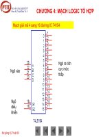
Unreinforced fabricated tee
A
4
A
2
L
4
th
C
L
RUN PIPE
C
L
BRANCH PIPE
Th
Pad reinforced fabricated tee
A
4
A
2
A
1
A
1
L
4
Tb
Tb
tb
tb
A
3
A
3
A
3
A
3
A
4
A
4
d
2
d
1
d
2
d
1
d
2
d
2
th
c+Mill Tol.
c+Mill Tol.
C
L
RUN PIPE
C
L
BRANCH PIPE
c+Mill Tol.c+Mill Tol.
th
th
Th
Tr
A
2
A
2
Figure 2.13 Branch connections.
Example 2.7a metric units, – Intersection:
DN 200;
T
= 8.2 Nom. wall x DN 100; T = 6.0 mm Nom. wall, pad reinforced intersection,
pad dimensions:
r
T
= 8.2 mm, diameter = 203.2 mm.
I. Nomenclature. (Reference Fig. 304.3.3)
T = 204°C; P = 4135 kPa; c = 2.5 mm; T
r
= (8.2 - 1.0) = 7.2 mm
D
h
= 219.1 mm; T
h
= 8.2 mm; Header Material: A 53 Gr. B EFW; E = 0.85
D
b
= 114.3 mm; T
b
= 6.0 mm; Branch Material: A 53 Gr. B SMLS; E = 1.0
Material SE; Header: 117 MPa; Branch: 118 MPa
T
h
=7.2mm T
b
=5.2mm (T -12¹⁄₂ % mill tolerance)
d
1
=D
b
-2(T
b
- c) = 114.3 mm - 2 (5.2 mm - 2.5 mm) = 108.9 mm
d
2
=thegreaterofd
1
or (T
b
-c)+(T
h
-c)+d
1
/2
d
2
= 108.9 mm
L
4
= the lesser of 2.5 (T
h
-c)or2.5(T
b
-c)+T
r
L
4
= 2.5 (7.2 mm - 2.5 mm) = 11.7 mm
The pressure design thickness for the header and branch pipes, calculated using equation (3a):
t=(PxD)/2(SE+PxY); t
h
= 3.8 mm, t
b
=1.7mm
II. Required Area
A
1
=(t
h
xd
1
)x(2-Sinβ) = 413.8 mm
2
CASTI Guidebook to ASME B31.3 - Process Piping - 2nd Edition
Chapter
3
FLEXIBILITY ANALYSIS OF
PIPING SYSTEMS
The safety of a piping system subjected to a temperature change and resulting thermal displacement
is determined by a flexibility analysis to insure against the following [¶319.1.1]:
1. Overstrain of piping components,
2. Overstrain of supporting structures,
3. Leakage at joints, and
4. Overstrain of connecting equipment, without material waste.
Required Analysis
Compliance with B31.3 Code flexibility analysis is a requirement of most petroleum and chemical
plant piping installations. The Code places the burden of this analysis the designer [¶300 (2)] and
holds the designer responsible to the owner for assuring that all the engineering design c omplies with
the requirements of the Code.
The Code is clear as to which piping systems require an analysis; all systems require an analysis
with the exception of the following: [¶319.4.1]
1. Those that are duplicates of successfully operating installations,
2. Those that can be judged adequate by comparison with previously analyzed systems, and
3. Systems of uniform size that have no more than two anchor points, no intermediate
restraints, and fall within the limitation of the equation:
()
Dy
L-U
K
2
≤
1
where: D = outside diameter of pipe, in. (mm)
y = resultant total displacement strains, in. (mm), to be absorbed by the piping system
L = developed length of piping between anchors, ft (m)
U = anchor distance, straight line between anchors, ft (m)
K
1
= 0.03 for U.S. customary units listed above (208.3 for SI units).
78 Flexibility Analysis of Piping Systems Chapter 3
CASTI Guidebook to ASME B31.3 - Process Piping - 2nd Edition
Example 3.1
Using the above equation, is a flexibility analysis required for the following installation?
A two-anchor routing of a DN 200 (NPS8) schedule 40 carbon steel pipe is shown in Figure 3.1 below.
The design temperature is 93
°
C (200
°
F), installed temperature = 21
°
C(70
°
F).
(e = 0.8 mm/m (0.99 in./100 ft) at 93
°
C (200
°
F), from Table C-1).
X
X
(anchor)
7620 mm (25 ft)
3660 (12 ft)
(anchor)
Y
Z
Figure 3.1 Two-anchor piping system.
Metric units: U.S. customary units:
D = 219.1 mm D = 8.625 in.
y=
22
ZY + y=
22
ZY +
∆Y = 3.66 m x 0.8mm/m = 3 mm ∆Y = 12 ft x 0.99 in./100 ft = 0.119 in.
∆Z =7.62 m x 0.8 mm/m = 6 mm ∆Z = 25 ft x 0.99 in./100 ft = 0.248 in.
y=
22
mm)6()mm3(
+
=7mm y=
()()
22
in.248.0in.119.0
+
= 0.275 in.
L = 3.66 m + 7.62 m = 11.28 m L = 12 ft + 25 ft = 37 ft
U=
()()
22
m62.7m66.3 + =8.5m U=
()()
22
ft25ft12 + = 27.73 ft
then 219.1 mm x 7 mm/(11.28 m - 8.5 m)
2
= 198 8.625 in. x 0.275 in./(37 ft - 27.72 ft)
2
= 0.0275
so
()
2
U-L
Dy
≤
208.3
()
2
U-L
Dy
≤
0.03
This two-anchor problem falls within the limits of the equation and does not require any further
thermal fatigue analysis.
Chapter 3 Flexibility Analysis of Piping Systems79
CASTI Guidebook to ASME B31.3 - Process Piping - 2nd Edition
Although this simple equation is useful in determining the need for formal stress analysis, it does
have limitations. No general proof can be offered to assure that the formula will yield accurate or
conservative results. Users are advised to be cautious in applying it to abnormal configurations (such
as unequal leg U-bends with L/U greater than 2.5 or near-saw-tooth configurations), to large
diameter thin-wall pipe (stress intensification factors of the order of 5 or more), or to conditions
where extraneous motions other than in the direction connecting the anchor points constitute a large
proportion of the expansion duty.
Allowable Stress Range
B31.3 establishes maximum allowable stress limits that can be safely accommodated by a piping
system before failure will commence for two separate stress loading conditions. These limits are for
stress levels that can cause failure from a single loading, S
h
, and those that can cause failure from
repeated cyclic loadings, S
A
.
The allowable stress range, S
A
, [¶302.3.5 (d)] is the stress limit for those stresses that are repeated
and cyclic in nature, or simply, it is the allowable stress to be compared to the calculated
displacement stress range, “S
E
” [¶319.4.4]. S
E
(a secondary stress) will be discussed in the
Displacement Stress Range section of this chapter.
The allowable stress range is presented in B31.3 by two equations:
Equation (1a):
S
A
=f(1.25S
c
+0.25S
h
)
S
A
, by equation (1a), is a “system” allowable stress of the entire piping system of the same material
and temperature.
and equation (1b):
S
A
=f[1.25(S
c
+S
h
)-S
L
]
S
A
, by equation (1b), is a “component” allowable stress at temperature where S
L
has been calculated
for that component.
S
c
and S
h
are the basic allowable stresses for the cold and hot conditions a s defined in the Defintion
and Basis for Allowable Stress section in Chapter 1. Their values are found in B31.3 Appendix A
Table A-1. (Note: For c ryogenic or cold pipe service, S
c
is taken at the operating temperature, S
h
is
taken at the installed temperature).
80 Flexibility Analysis of Piping Systems Chapter 3
CASTI Guidebook to ASME B31.3 - Process Piping - 2nd Edition
fisthestress-range reduction factor presented in B31.3 Table 302.3.5 or equation (1c):
f=6.0(N
-0.2
) ≤ 1.0
Values are as follows:
Cycles N Factor f
7,000 and less 1.0
Over 7,000 to 14,000 0.9
Over 14,000 to 22,000 0.8
Over 22,000 to 45,000 0.7
Over 45,000 to 100,000 0.6
Over 100,000 to 200,000 0.5
Over 200,000 to 700,000 0.4
Over 700,000 to 2,000,000 0.3
S
L
is the longitudinal stresses to be discussed later in the Sustained Load Stress section in this
chapter.
An example of the application of the allowable stress range equation (1a) is as follows:
Example 3.2
Calculate the S
A
for a piping system constructed of ASTM A 106 Grade B pipe material used in 260°C
(500°F) service, and with a design life of 18,000 thermal cycles.
Solution: From B31.3 Table A-1 for ASTM A 106 Grade B
S
c
= 138 MPa (20,000 psi), (at min. temp. to 38°C (100°F))
S
h
= 130 MPa (18,900 psi), at 260° C (500°F)
f = 0.8 (from B31.3 Table 302.3.5), then
Metric units U.S. customary units
S
A
= 0.8 (1.25 x 138 MPa + 0.25 x 130 MPa) S
A
= 0.8 (1.25 x 20,000 psi + 0.25 x 18,900 psi)
S
A
= 164 MPa S
A
= 23,780 psi
This piping system can be expected to operate safely provided the displacement stress r ange, S
E
, does
not exceed S
A
of 164 MPa (23,780 psi) and the number of thermal cycles is less than 18,000. (The
f factor although appropriate for the 18,000 cycles of this p roblem, is also suitable for 22,000 cycles as
shown in Table 302.3.5.)
The allowable stress range equation (1b) can be used as a design basis in place of equation (1a)
provided the longitudinal stresses due to sustained loads, S
L
, have been calculated for each
component and these longitudinal stresses are less than the hot allowable stress, S
h
,(S
L
≤ S
h
).