Intelligent Vehicle Technology And Trends Episode 1 Part 7 ppsx
Bạn đang xem bản rút gọn của tài liệu. Xem và tải ngay bản đầy đủ của tài liệu tại đây (378.38 KB, 20 trang )
SafeTRAC uses a video camera to watch the road ahead, track the road and
vehicle position in the lane, monitor for weaving and lane drifts, and alert the driver
before a road or lane departure. The camera is mounted in a center position on the
windshield interior. Lane detection software tracks both lane markings and subtle
features such as the road edge and oil strips in the lane center area. Assistware has
optimized the lane-tracking algorithms so that the system performs well in a wide
variety of lighting, environmental, and pavement conditions.
SafeTRAC is unique in that the system provides a continuous indication to the
driver of vehicle position within the lane, via a simple graphical display. Per Figure
6.2, lane position is shown as a vertical “dash” character moving between two verti
-
cal “dash” lane boundary characters. An audible alarm is sounded if the vehicle
begins to depart the road or cross into another lane without the turn signal acti
-
vated. Seat vibrators can also be activated from the system output. Sensitivity is
adjustable, and the system automatically disables when road features are inadequate
for lane detection.
The system also continuously tracks the driver’s relative accuracy over time in
maintaining lane position to provide an “alertness feedback score” (shown as “86”
in Figure 6.2). In this way, erratic or degraded driving can be detected even if lane
departures are not occurring. This feedback can help the driver realize his or her
level of fatigue may be more than they thought, and data such as this can also be
logged for fleet managers to review as an indication of needed driver training.
Iteris LDWS [8–10] The Iteris Autovue system, shown in Figure 6.3, is the market
leader in LDWS. Originally introduced in Europe in 2000, over 8,000 units have
since been sold there and sales are averaging 4,000 systems annually. Iteris estimates
that the systems have logged one billion kilometers thus far in Europe alone. A
modified system entered the European motorcoach market in 2004. In the United
States, Autovue is now available as a factory option from several truckmakers and
over 600 units have been sold. In the auto market, Iteris is also the supplier of the
102 Lateral/Side Sensing and Control Systems
Figure 6.2 SafeTRAC camera (left) and combination processing and driver interface unit (right).
(Source: AssistWare Technology.)
LDWS introduced by Infiniti and Citroën. Autovue is sold as an integrated system
installed by the manufacturer.
Autovue detects lane boundaries through video-based image processing as well.
The system works in full daylight and at night with headlights on, as well as any
weather in which lane markings are visible. This includes heavy fog, as the viewing
proximity is very close to the front of the vehicle. A “virtual rumble strip” warning
is provided to the driver if a lane departure is imminent, using the left or right audio
speakers to indicate the direction of the lane departure. An exception is the Euro-
pean motorcoach version, which provides directional warnings via seat vibration.
Iteris notes that the system promotes the use of turn signals when changing lanes
and conditions drivers to have a keen sense of “lane position awareness” and
remain in the lane center.
In surveys conducted with over 200 truck drivers in the United States and
Europe who have used Autovue, 75% or more of the drivers drove regularly with
the system enabled and believed the warnings came at the right time, the system was
valuable even with occasional false alarms, and the system could prevent crashes.
MobilEye LDWS [11, 12] MobilEye has pioneered the development of
application-specific integrated circuits for driver assistance with their EyeQ™
system-on-a-chip (SoC). The company’s vision-sensing approach based on the
EyeQ™ provides lane departure warning as well as forward collision warning (see
Chapter 7). The system became available to automotive and truck fleets as an
aftermarket product in 2004. The system also mimics the rumble strip sound as a
way of alerting the driver to a lane departure.
MobilEye’s algorithmic approach fits a three-parameter road model that
accounts for lateral position, slope, and curvature. The curvature parameter is
used for increasing the warning reliability on curved roads and for estimating
time to lane crossing. In addition the system retains multiple lane models (such
as urban roads, merging lanes, or exit lanes) so that it can switch between them
6.1 Lane Departure Warning System (LDWS) 103
Figure 6.3 Iteris’s first generation LDWS. Used in the United States commercial market starting in
2002. (Source: Iteris, Inc.)
instantaneously to find the best match for the conditions. During heavy rain, the
visual interference caused by raindrops and windshield wiper motion are pro
-
cessed so that lane detection is not impeded.
Toyota Rearview System [13, 14] The Toyota LDWS on the market in Japan takes
an innovative approach in using the rearview camera for double duty. Rearview
cameras are primarily intended to assist the driver by providing an image of the area
behind the vehicle on the navigation screen during parking maneuvers. The Toyota
system, developed cooperatively with supplier Aisin, uses the same camera to look
at lane markings immediately behind the vehicle while on the highway to realize the
LDWS function.
6.1.3 LDWS Evaluations
Researchers in Europe and the United States have conducted evaluations of the
behavioral effects, driver acceptance, and overall safety effectiveness of LDWS for
heavy truck operations. These types of field trials provide valuable insight into “real
world” use of such systems—are they truly supporting the driver? Two projects are
briefly reviewed here.
LDWS Evaluations Conducted by the Dutch Ministry of Transport [15] The Dutch
Ministry of Transport sponsored field trials of LDWS during 2002 and 2003. The
trials were conducted by a team of researchers led by TNO and focused on
professional drivers operating heavy-duty trucks and long-distance buses.
The research was organized into six major work packages:
•
Analysis of the driving task and the role of LDWS;
•
Behavioral effects of LDWS;
•
Expert opinion of traffic flow effects of lateral driver support systems;
•
Acceptance of LDWS;
•
Infrastructural consequences of LDWS;
•
Relation of LDWS to the use of narrow road lanes.
The test fleet consisted of 35 trucks and five motorcoaches. Five of the trucks
had data recorders to collect detailed information. Several different LDWS, typical
of those offered commercially, were used.
Overall, the effects of LDWS on traffic safety were seen to be positive. The
results indicated that, with all trucks in the Netherlands equipped, approximately
10% of injury crashes involving heavy vehicles could be prevented. With respect to
traffic flow, LDWS are not expected to have either a positive or negative influence,
other than the reduction in congestion due to fewer truck crashes.
The Dutch government has investigated reconfiguring existing roadways into
narrower lanes to create additional lanes as a way of reducing congestion. There
-
fore, LDWS were evaluated for their ability to help drivers maintain correct lane
position in narrow lanes. Truck driving simulator experiments were conducted in
which the lane widths on the virtual road varied from 3.5m down to 2.9m. A dis
-
traction task was intentionally introduced to stress the lane-keeping task of the
104 Lateral/Side Sensing and Control Systems
driver. The study results showed that the LDWS system improved lane-keeping,
particularly for the narrower lane widths. At the same time, however, drivers
reported driving to require more effort when using the LDWS.
LDWS enjoyed a high degree of user acceptance among drivers who used the
systems during the on-road evaluation. This was also the opinion of managers at the
transport companies involved, a key point given that company management must
see benefits to make decisions to buy such systems. A total of 75% of the drivers had
positive opinions of LDWS, and over 50% stated that they would prefer to drive
with such a system installed in their vehicle. However, 21% of drivers stated that
they would prefer vehicles without LDWS.
On the positive side, drivers noted fewer “startle” reactions during lane
departure events by using LDWS, as they were advised earlier in the event and
therefore could respond more gracefully; similarly, reaction times to take cor
-
rective action were reduced. Interestingly, 60% of drivers concluded that the
system caused them to pay more attention to the driving task. Increased comfort
levels were noted, as well.
On the down side, 20% of the drivers felt that the system could cause a startle
response that might be worse than crossing the lane line; this factor was seen as
potentially being related to the loudness of the audible warning. Further, drivers
perceived 25% of the warnings as needless (i.e., false alarms). Obviously, this
would argue for the provision of sensitivity and volume adjustments being available
to the user, at the level of either the fleet or individual driver.
Mack Trucks/U.S. DOT LDWS Field Operational Test [16] The U.S. DOT Federal
Motor Carrier Safety Administration, as part of the IVI program, partnered with
Mack Trucks and McKenzie Tank Lines to evaluate the SafeTRAC LDWS on a fleet
of approximately 20 tractor-tankers. The test, which is ongoing, involves extensive
data collection on each of the trucks. To provide a basis for comparison, lane
detection and data collection is active on all trucks, but the driver warning is
disabled for a subset of the fleet. For the trucks with activated driver interfaces,
driver acceptance is being evaluated through the use of surveys.
The onboard measurement system provides the following critical information:
•
Vehicle state;
•
Driving behavior;
•
Roadway alignment and lane markings;
•
Presence of precipitation;
•
LDWS operational status;
•
LDWS alerts;
•
Lateral velocity and lateral acceleration during lane departure events;
•
Surrounding traffic;
•
Location.
When a lane departure event occurs, data from the previous 30 seconds and the
following 30 seconds is captured in one-second intervals. The data acquisition sys
-
tem logs several different types of lane departures: less than 10 inches, 10–18 inches,
6.1 Lane Departure Warning System (LDWS) 105
and greater than 18 inches. When the field testing is completed in 2005, over one
million miles will have been logged by the test fleet. The data will be analyzed to
assess the overall safety benefit of the system, as well as any negative impacts.
6.2 Road Departure Warning Systems (RDWS)
As one might expect, RDWS are similar to LDWS in providing lane tracking. How
-
ever, there are some important differences and specialized applications in RDWS
that are reviewed here.
6.2.1 Curve Speed Warning
Curve speed warning systems advise drivers when their speed is too high for an
upcoming curve. These systems are currently in developmental stages and have not
yet been introduced commercially; however, this application is expected to be
brought to market in the near term.
The Digital Map Approach [3, 17] Here, the premise is simple: Digital maps
produced for use in onboard navigation systems could contain sufficient road
geometry information to enable a safe speed estimate to be generated for
upcoming curves in typical road conditions. When a vehicle is approaching such
a curve, an onboard processor compares this estimate with the actual vehicle
speed. If the threshold speed is exceeded, a warning is issued to the driver or
speed is automatically reduced. While some road geometry is available in
current digital maps, it is generally agreed that enhanced next generation maps
are needed for curve speed warning to be sufficiently reliable.
Curve speed warning, as well as vehicle control techniques to reduce speed auto-
matically, have been addressed by projects in the United States and Europe examin-
ing the application of digital maps to driver assistance in general. Ford and GM
separately prototyped curve speed warning approaches for both warning and vehi
-
cle control in the United States EDMap project, and BMW did the same within the
European ActMAP project. BMW’s approach provides a good example of an
advanced system implementation. BMW uses an active accelerator to provide feed
-
back to the driver in a manner that provides both warning and a form of control.
Whenever the current speed is deemed too high for the road conditions, the accelera
-
tor pedal presents a slight but insistent feeling of resistance to indicate that the driver
should slow down. Through its respective position, the active accelerator pedal also
“suggests” the right speed to the driver. However, the system cannot be all-know
-
ing, so this feedback always remains a suggestion for the driver to accept at his or
her discretion. In this way, the driver remains in the loop and the amount of feed
-
back is based on the deviation between expected and actual behavior.
In addition to curve radius and curve angle, a fully informed curve speed warn
-
ing system would also incorporate parameters such as surface quality, street width,
number of lanes, shoulders, visibility (daytime), weather (for determining friction),
and driving style of the driver. As curve speed warning systems evolve, they can take
advantage of such data from other sensor systems to enhance the safe speed
calculation.
106 Lateral/Side Sensing and Control Systems
Infrastructure-Oriented Curve Speed Warning [18] In Japan, AHSRA has pursued
an infrastructure-centered approach to a curve speed warning that focuses on
particular road sections known to be hazardous. While static roadside signs can
be placed to provide general warnings to all drivers, these are not deemed to be
sufficiently effective—drivers who are going too fast for the curve need to
receive a direct warning. Prior to the curve, therefore, speed detectors and
road-vehicle communications equipmentareinstalledsoastowarndriversif
their speed is too high.
This system approach is being evaluated at several sites. On National Highway
25 in Naga Prefecture, the “Omega Curve” is infamous for its steep downgrade and
length, which tends to cause vehicles to accelerate to unsafe speeds. Another site,
National Road 246 in Kanagawa Prefecture, is a two-lane bidirectional road in
which one section has two consecutive curves on a downslope, such that the second
curve is not in view and tends to surprise drivers. Lane departures caused by exces
-
sive speed for the situation have resulted in serious head-on collisions in this section.
Testing is also under way on the Tomei Expressway and at several metropolitan
freeway interchanges with complex and sharp flyover ramps.
6.2.2 U.S. DOT Road Departure Warning Field Operational Testing [19–22]
In 2001, U.S. DOT partnered with the University of Michigan Transportation
Research Institute, Visteon Corporation, Navteq, and Assistware in a field
operational test project focused on RDWS. The project defines and evaluates a
system which warns drivers when they are about to drift off the road and crash
into an obstacle, as well as when they are traveling too fast for an upcoming
curve. As shown in Figure 6.4, technologies include a vision- and radar-based
6.2 Road Departure Warning Systems (RDWS) 107
New high-
definition
maps and
GPS
Short-range
radar sensor
Camera-based
lane detection
Short-range
radar sensor
Long-range
radar sensor
Long-range
radar sensor
Integrated
human
system
interface
Road departure crash warning system:
Combines curve speeds and lateral drifts warnings into one uniform function
Figure 6.4 Road departure crash warning system under evaluation by the U.S. DOT.
(Source: Visteon.)
lateral drift warning system and a map-based curve speed warning system. A
photo of the radar sensors, which are installed on each side of the vehicle, is
shown in Figure 6.5.
The lateral drift warning subsystem takes road detection a step further than a
typical LDWS. Using machine vision, it assesses the existence and width of the road
shoulder. Furthermore, forward- and side-looking radar detects the presence of any
obstacles on the shoulder (such as parked cars) or the roadside (such as poles or
guardrails). Armed with this information, the driver warning modality can be more
situation-aware. In the case of no shoulder or an obstructed shoulder, the warning
would be at its most urgent level; conversely, when the shoulder is broad and unob
-
structed, the driver might only receive an advisory message. Audio, visual, and seat
vibration warnings are used to present the various warning levels.
For the region ahead and nearby the vehicle, data collected includes the following:
•
Upcoming road curvature;
•
Lane width;
•
Number of lanes;
•
Paved shoulder width;
•
Boundary marker types;
•
Any temporary roadside objects (such as parked vehicles);
•
Permanent roadside objects (such as bridge abutments).
At the heart of the system is a “situation awareness module,” which fuses data
coming from the sensors to understand the situation and calculate available maneu-
vering room.
108 Lateral/Side Sensing and Control Systems
Side-looking
radar
Forward-
looking radar
Figure 6.5 Side- and forward-looking radar units installed on a Nissan Altima for the road
departure crash warning system. (Source: UMTRI; photo: Shekinah Errington.)
System development is complete and field data collection began with a test fleet
of 14 Nissan Altima’s in early 2004. Plans called for 78 people to drive the vehicles
over a 10-month period. Data collection will be completed in early 2005.
6.3 Lane Keeping Assist Systems (LKA)
6.3.1 System Approaches
Lane-keeping systems are intended as convenience products by reducing the driver’s
need to make the frequent minute steering corrections that are a normal part of driv
-
ing. The lane detection function is handled as described in section 6.1 and active
steering input is added by the LKA system. For automotive products, the paradigm
is one of shared control, whereas in specialty applications such as transit buses, full
steering control is sometimes provided.
Automotive LKA Systems For automotive implementations of LKA, automatic
steering torque is provided by a motor integrated with the vehicle steering system.
Future systems will likely use steer-by-wire to “actuate” steering. Per Figure 6.6,
torque increases as the vehicle nears a lane edge to create a “driving in a bathtub” type
sensation for the driver. Surprisingly, the delivered torque to adjust vehicle direction at
highway speeds is quite small. Therefore, the systems are easily override-able by even
the weakest drivers—in fact, the systems were tested with specially selected “weak
drivers” in Japan before being introduced to the market there!
Based on the shared control paradigm, automotive LKA require driver input to
remain enabled. Approximately 80% of control is provided by the system and 20%
by the driver, with the systems only operating on highways of rather modest curva-
ture. If the curvature limits are exceeded, the system disables automatically [39].
6.3 Lane Keeping Assist Systems (LKA) 109
Max torque
driver to feel
Lane
marker
Assist torque
Lane
position
Lane departure
warning area
Lane departure
warning area
Center
Assist torque
Figure 6.6 A relative indication of steering assist torque provided in steering assist systems.
(Source: Honda.)
BMW’s LKA system, called heading control, uses onboard sensors to analyze
any crosswind, curves or ridges in the road, in addition to detecting lane edges [23].
It uses this information to calculate optimal steering behavior and define tolerance
limits; should these be exceeded, the system applies force to the steering wheel to
suggest corrections. Drivers then decide to accept the recommendation or initiate
another action, such as overtaking. Heading control is currently under test by BMW
and is expected to be introduced to the market soon.
Lane-keeping performance for LKA systems is typically better than human driv
-
ers can maintain. One study showed maximum lateral deviation within the lane at
0.2m for the automatic lane- keeping system, as compared to 0.4m for an experi
-
enced test driver.
When lane-keeping support systems are discussed, questions frequently arise as
to the driver’s ability to remain alert. Is the system providing too much assistance,
such that the driver tunes out? This is one reason that system designers have adopted
the 80/20 rule for first generation systems, so that driver input is required for the sys
-
tem to remain active. Research on this topic is discussed in Chapter 12.
Full Steering Support for Transit Bus Applications BRT systems rely on various
methods to provide express service to travelers as compared to automobile travel, so
as to attract greater bus ridership. One approach is to provide exclusive lanes for the
buses. In many cities, the creation of such lanes is a major challenge given the
existing development and already crowded streets. Real estate is at a premium, and
even fractions of a meter in the width of a new lane can make or break the viability
of new bus service of this type. When the pressure is on to make the lanes as narrow
as possible (only centimeters wider than the width of the bus itself), automatic
steering assistance is called for.
Given the limited lane-miles of such implementations, various approaches to
lane-tracking can be used, including special infrastructure treatments. The CIVIS
system, developed by Irisbus, uses image processing to detect distinctive lines
painted on the road surface (Figure 6.7), and a guidance module synthesizes this and
110 Lateral/Side Sensing and Control Systems
Figure 6.7 Specialized pavement markings used by the CIVIS system for lane-tracking.
(Source: Irisbus.)
other relevant inputs to generate steering commands (Figure 6.8). The Phileas sys
-
tem, developed by APTS, relies upon magnetic markers installed in the road surface.
6.3.2 LKA Systems on the Market
Automotive Systems
LKA systems were introduced initially by Nissan in Japan in
2001 [24] and are now available from all major automakers there. The system
philosophy is that steering assist is for the purpose of improved stability and
reduced driver fatigue; it is not intended for autonomous driving. The systems on
Japanese vehicles typically operate only over 65 km/hr on roads with a radius of
curvature of 1,000m or more. However, the Honda system operates on road radii
down to 230m, which essentially covers all Japanese highways.
An example of the Nissan LKA driver interface on the market is shown in
Figure 6.9 [38]. This interface is placed within the instrument cluster and shows the
activation of the LKS function by illuminating the “LANE” icon. When the system
is actively tracking the lanes, an image is illuminated to iconically illustrate road
lanes. In this image, a vehicle icon is also illuminated to indicate that the ACC sys
-
tem is tracking a vehicle ahead.
Similar systems are expected to be introduced on the European market within
approximately three years, and North America not long afterwards. The market
pull in North America is seen as particularly strong, given the long, monotonous
intercity trips undertaken by Americans for business and vacation travel on the
nation’s interstate highway system.
6.3 Lane Keeping Assist Systems (LKA) 111
Vision module
Guidance module
Special painted lines
Steering
sensor
Electric
actuator
Camera
Figure 6.8 CIVIS lateral guidance approach. (Source: Irisbus.)
Figure 6.9 Nissan LKS driver interface integrated into instrument panel. (Source: Nissan.)
Bus Transit Systems Automated and semiautomated bus systems are now in operation
in various parts of the world. The first CIVIS systems were installed in France in 2001
and are now operational in the French cities of Clermont-Ferrand and Rouen. CIVIS
was also the first semiautomated bus system installed in the United States, with service
initiated in Las Vegas in 2004 [25]. As shown in Figure 6.10, CIVIS buses are highly
stylized so as to reflect the high-technology nature of the system.
CIVIS provides lateral control only. The Phileas system in the Netherlands and
the Intelligent Multimode Transit System in Japan incorporate both lateral and lon
-
gitudinal control and are further discussed in Chapter 10.
6.4 Parallel Parking Assist [14, 26, 27]
In 2003, Toyota surprised the IV world by introducing yet another system based on
their rearview camera. Keying on the great challenges encountered in parking in
Japan, a semiautomated parallel parking assistant called Intelligent Parking Assist
(IPA) was introduced on its Prius hybrid. The system relies upon the rearview cam
-
era and image processing for sensing and provides automated steering. It frees the
driver from the tedious, and sometimes unsuccessful, precision maneuvering needed
to parallel park their vehicle successfully. The system is designed so that throttle and
braking is still under driver control. Developed by supplier Aisin Seiki Co. in cooper-
ation with Toyota, IPA builds upon an earlier parking assist system that performed
the same sensing computations but provided only voice prompts, not steering, to
guide the driver.
Toyota demonstrated the system at the ITS World Congress in Madrid in
November 2003. After a brief demonstration by a helpful Toyota engineer, your
intrepid author was allowed at the controls. The system has a brief learning curve,
during which he was coached in using touch-sensitive arrows on the display screen
to position a green rectangle over the empty parking spot, which could be seen in the
video display sourced from the rear-mounted camera. Once properly indicated, the
“set” button was pressed. A message was displayed that reminded me that, as driver,
112 Lateral/Side Sensing and Control Systems
Figure 6.10 CIVIS Vehicle in operation in Las Vegas. (Source: Irisbus.)
I remain fully responsible for the operation of the vehicle, and the proper acknowl
-
edgment key was clicked to indicate my assent and understanding. At this point, I
was in charge of the throttle and accelerator and the car was poised to handle the
precise steering necessary to adroitly move into the targeted parking space. From a
driver perspective, it was simply a matter of watching the steering wheel and the
scenery as the Prius glided into the designated spot. It was then my job as driver to
place the vehicle in forward gear and finish the positioning process for a perfect
parallel parking job.
Even though the functions implemented in IPA are only basic aspects of the
driving experience for the average automobile customer, the significance of this type
of product should not be lost. Toyota’s automated parking assist provides a superb
testbed for engineers to understand the performance of their automated steering in
the real world, in the hands of real customers. Refinements stemming from this type
of product will likely contribute to the future introduction of fully automated steer
-
ing systems for all types of driving.
6.5 Side Sensing: Blind Spot Monitoring and Lane Change Assistance
(LCA)
Side sensing supports drivers in detecting vehicles within the proverbial “blind
spot” to the rear left of their own vehicle, to facilitate safe lane changes on motor-
ways. LCA incorporates basic blind spot monitoring, which is fundamentally a
short-range sensing mode, with longer range sensing to detect vehicles in adjacent
lanes, which may be rapidly approaching and could also pose a hazard in a lane
change maneuver.
Being a simpler problem, blind spot monitoring systems are more mature and
basic systems are on the market. The primary sensing modality is short-range radar,
typically operating at 24 GHz. Vision-based systems for both blind spot monitoring
and LCA have also been implemented. Ultrasonics can be used for low-speed appli
-
cations in urban operations. Additionally, a lidar system is being tested by the ITS
Institute at the University of Minnesota to assist bus drivers with merging assist and
blind zone reduction [2]. LCA based on laser scanners has also been developed to
sense approaching traffic at a range of up to 200m [28]. The following sections
review some representative systems.
6.5.1 Radar-Based Systems [29–31]
The “granddaddy” in blind spot monitoring is the Eaton VORAD system, which was
introduced to the heavy-truck market in the early 1990s, combined with forward colli
-
sion warning. The VORAD system uses range-gated Doppler radar at 24 GHz to help
drivers detect vehicles in the right-side blind spot of the typical large truck. The sensor
is pointed at a right angle to the truck and the active sensing zone is 2–10 feet to cover
the adjacent lane. The VORAD system is further described in Chapter 7.
For the automotive market, the challenge is to offer radar-based sensing systems
at a much lower cost than that the systems sold to truckers. Many suppliers have
radar-based blind spot monitors in development, although their attributes differ.
Here we provide a brief sketch of systems from Valeo Raytheon and Visteon.
6.5 Side Sensing: Blind Spot Monitoring and Lane Change Assistance (LCA) 113
The Valeo Raytheon system uses 24-GHz radar sensors to monitor the blind
spot on both sides of the vehicle. If a vehicle is present in the blind spot, the system
alerts the driver through a visible icon. The system range extends to 40m, with a
150-degree broad field of view. The radar is a multibeam system operating in a nar
-
row bandwidth. Using several beams to recognize objects in the blind spot allows for
high accuracy in determining the position and distance of the object as well as its rel
-
ative speed. The sensors are integrated into the vehicle behind the rear plastic
bumper. Valeo Raytheon expects its system to appear on production vehicles
around 2006.
The Visteon system is a close-in blind spot monitor, covering a detection range
of 6m, again using 24-Ghz radar. Its driver interface approach uses an illuminated
icon integrated into the side mirror. Per Figure 6.11, the alert zones are programma
-
ble, so that a customizable zone can be provided both laterally and longitudinally to
fit specific product needs or regulations. As is key with all blind spot monitors, the
system does not alarm on stopped objects, such as guardrails. Also, to avoid nui
-
sance alerts, the system is designed to delay an alarm for what appears to be an over
-
taking vehicle that is likely not a threat. If the approaching vehicle does indeed pass
the host vehicle, no alarm is sounded at all.
6.5.2 Vision-Based Systems [32]
MobilEye offers blind spot monitoring and LCA using a single camera solution. The
system detects moving and stationary vehicles in adjacent lanes and determines the
vehicle range, relative speed, lateral position and time to contact by monocular
image processing. A warning is provided when vehicles in an adjacent lane do not
permit a safe lane change maneuver.
The vision sensor is typically located on the vehicle’s sideview mirrors and sup-
ports both right and left sides. Vehicles close to the subject vehicle are detected, even
if the adjacent vehicles are only partly visible to the camera. It detects close-by vehi-
cles based on visual motion analysis whereas vehicles farther away are detected
114 Lateral/Side Sensing and Control Systems
Figure 6.11 Programmable alert zones in side object detection enables customization. (Source:
Visteon.)
using pattern recognition. The application discerns the lane position of all detected
target vehicles so as to suppress warnings for vehicles that are in nonadjacent lanes
and therefore not a hazard. If there are no lane markings at all, or the markings are
not detectable, the warnings are determined based on the lateral distance of the
approaching or passing vehicle.
6.5.3 Ultrasonic-Based Side Object Sensing For Transit Buses [33]
As described in Chapter 4, the U.S. Federal Transit Administration is developing
performance specifications for several types of collision avoidance systems. The
agency’s work in side sensing was evaluated on 100 buses within the Port Authority
of Allegheny County system in Pittsburgh, Pennsylvania.
Transit bus operations suffer from numerous property damage incidents result
-
ing from maneuvering large buses in tight urban areas. Based on average property
damage costs for the transit industry, a side object warning system costing $3,000
would have a payback in less than three years. Taking into account other factors
such as legal costs, these types of systems could potentially pay for themselves
within a single year.
The approach with the Pittsburgh bus fleet was to integrate a number of ultra
-
sonic sensors within a plastic strip running along each side of the buses. These buses
were operated in regular service during 1999 and 2000. In a side-by-side compari-
son, a fleet of buses equipped with side object sensing had 100 such collisions in
2001, compared to almost 300 collisions for an equal number of unequipped buses
over the same period. The system has subsequently been commercialized with a
reduced set of sensors focusing on the vehicle areas most likely to be involved in
potential collisions.
6.6 Comprehensive Lateral Control Assistance (LCA)
The systems discussed thus far can obviously be integrated into a more comprehen
-
sive suite of applications based on radar and vision sensing. Two such approaches
are reviewed here.
6.6.1 INVENT: LCA [34]
The German INVENT R&D program includes LCA within the suite of applications
addressed by the program subtasks Detection and Interpretation of the Driving
Environment and Anticipatory Active Safety. This work is motivated by data that
shows that 35% of fatal crashes in Germany in 2001 were due to road departure.
In the INVENT program, LCA is a comprehensive package of applications
including lane departure warning, road departure warning, lane keeping assist,
blind spot sensing, and lane change assist. Some LCA work is devoted specifically to
support heavy truck drivers, to relieve them of the tiring tasks of driving “against”
wind gusts, roadway banking, and road grooves, through automatic compensation
in the steering mechanism.
Furthermore, the Predictive Control of Vehicle Dynamics program component
takes a more comprehensive approach, addressing any situation in which vehicle
speed and orientation are critical. The goal here is to avoid entering the hazardous
6.6 Comprehensive Lateral Control Assistance (LCA) 115
range of vehicle dynamics through active intervention. In the initial phase, targeted
braking/steering interventions are implemented to support the driver when in dan
-
ger of losing control in holding the lane or road. The second phase implements more
significant preventive measures, via braking and steering to improve lane orienta
-
tion. For instance, the orientation of the vehicle may be automatically adjusted when
approaching a curve too rapidly.
6.6.2 PReVENT [35]
Within the European PReVENT integrated project, the lateral support and driver
monitoring subtask is relevant here. The subtask includes the first European-level
R&D in lane-keeping support, called SAFELANE. Also, lane change assistance and
blind spot monitoring is being addressed in a subproject called LATERALSAFE.
These applications are depicted in Figure 6.12. A particular project focus is to imple
-
ment systems that support the driver in adverse or low visibility conditions. Driver
monitoring systems are also integrated into these applications.
The work, which began in 2004, is expected to result in a lane-keeping support sys
-
tem for situations with poor road and environmental conditions, an integrated driver
support system for handling critical driving situations, and lateral support in all traffic
scenarios. For the demonstrations planned in 2006, two LATERALSAFE cars and one
truck simulator will illustrate multiple system approaches and driving scenarios; also,
two trucks and one car will demonstrate SAFELANE lane-keeping support.
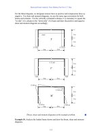
6.7 Rollover Collision Avoidance (RCA) for Heavy Trucks [36, 37]
RCA does not involve external sensing and as such does not precisely fit the IV sys-
tem definition in Chapter 1. However, the safety contribution of these systems is so
significant, particularly for large trucks, as to merit some attention.
Electronically controlled stability systems have recently become available for
automobiles and are seen as particularly important in preventing rollovers of sport
116 Lateral/Side Sensing and Control Systems
LATERALSAFE
10s
100 ms1s
10 ms
Lane
support
Lane change blind spot
Lane support
SAFELANE
Lane support
SAFELANE
Rear detection
and lane change assistance
LATERAL SAFE
Figure 6.12 Lateral assist applications suite in the European PReVENT project. (Source: PReVENT.)
utility vehicles. These systems use complex algorithms to detect roll forces and acti
-
vate differential wheel braking to compensate and prevent the roll event.
RCA for tractor-trailer truck configurations is a different case for several
reasons. First, while the trucker has full braking control of both tractor and trailer,
any specialized electronics must be limited to the tractor. This is because trailers are
mated to tractors randomly in many trucking operations, and special interfaces and
equipment on the trailer is therefore infeasible, particularly when the trailer is
owned by a different company than the tractor owner, which is commonly the case.
Also, the effects of a truck rollover go far beyond the individual vehicle. When a
rollover blocks several lanes of traffic, thousands of hours of delay are incurred by
other travelers. Further, tanker trucks, often carrying flammable materials such as
gasoline, are more prone to rollovers due to “slosh” of their cargo. In the abso
-
lute worst cases, a massive fireball creates a major disaster site. We’ve all seen the
news reports.
In the United States, rollovers comprise 6% of combination vehicle crashes, of
which over 50% involve personal injury. The average cost of such a crash is in the
range of $120,000, but can be more than an order of magnitude greater when haz
-
ardous material spills occur.
In North America in particular, tractor-trailer combinations have a long wheel-
base, and high centers of gravity (CG) are common due to the cargo. Both of these
factors increase susceptibility to a rollover. Maneuvers promoting rollovers include
the following:
•
Excessive speed entering a curve;
•
Maintaining a constant speed in a reducing radius curve;
•
Accelerating in a curve;
•
Sudden lane change.
A compounding factor is that drivers have difficulty sensing proximity to the criti
-
cal vehicle rollover threshold. Amazingly, the trailer’s wheels can be lifting off the
ground on one side and this action is undetectable within the tractor (see Figure 6.13).
Rollovers occur in situations of a high lateral coefficient of friction (i.e., dry
pavement). When driving speeds exceed the threshold and surface friction is suffi
-
cient to resist sliding, the vehicle is prone to rollover. If the road surface is wet and
friction low, then the trailer slides and a jackknife event is the result.
Rollover risk is calculated based on direct measurement of lateral acceleration
and estimation of the vehicle CG. The CG is estimated using a load distribution
model and calculated vehicle mass. The mass is calculated from comparing engine
torque to the acceleration achieved, along with other factors such as tire size. The
system intervenes through engine control or braking to reduce speed, which will in
turn reduce the roll forces.
RCA accelerometers and the embedded computer system are typically incorpo
-
rated in the same circuit boards used for antilock braking and traction control on
the tractor body.
RCA systems have been developed by several truck suppliers, including Meritor
WABCO and Bendix. The systems are available on Freightliner trucks and other
truck OEMs are expected to follow suit very soon.
6.7 Rollover Collision Avoidance (RCA) for Heavy Trucks 117
6.8 Summary
From this review of lateral and side sensing systems, we can see that there is a wealth
of applications, most of which can supported by range sensing (radar, lidar, laser
scanner) or image processing. LDWS are quite mature and expected to proliferate
fairly quickly, picking up momentum within the trucking industry and gradually
being offered to more models on the car side. LDWS and blind spot and LCA sys-
tems offer a vital advantage in that drivers will perceive the presence and usefulness
of the systems virtually every day—this way, they clearly see the value gained from
purchasing the product. However, given the daily visibility of these systems, a
potential downfall is the potential that the systems will sound too many false alarms
and become a nuisance. Early indications from LDWS usage suggest that false
alarms are at a reasonable level; this challenge remains for blind spot and LCA
systems as they are brought to market.
Another advantage of LDWS is that they require no connection to the vehicle
and can easily be mounted within the driver’s compartment. Their simplicity allows
for after-market sales and relatively easy integration into factory vehicles.
Lane-keeping assistance is an appealing idea to the average driver as another
means of relieving the tedium of normal driving. However, human factors analysts
are concerned that LKA combined with ACC gives drivers “too much” support. As
we will see in Chapter 12, results so far are reassuring, but this will remain an area of
debate for some time. Fortunately, having systems on the market in Japan provides
solid user data against which to compare human factors laboratory experiments.
For bus transit, LKA has become an enabling technology for exclusive lane opera
-
tions, allowing transit operators to offer a light-rail type experience at a fraction of
the cost.
118 Lateral/Side Sensing and Control Systems
Figure 6.13 Photo of tractor-trailer on a test track invoking roll forces (note that the tractor is rel
-
atively stable while the trailer is in serious trouble). (Photo courtesy of Meritor WABCO.)
ADAS supported by digital maps and satellite positioning are moving toward
reality, and most likely curve speed warning will be one of the first embodiments of
this concept.
What about automated parking assistance? No doubt it passes the “coolness”
test, but how likely is it to be a market success? The key is customer pull—parallel
parking is a common task for Europeans and Japanese, but fairly rare for Americans
who are more likely to be pulling into the parking lots of shopping malls. As the
United States is the largest market, automated parking assistance may not be see
huge sales but will certainly serve as a launching pad for other applications based on
automatic steering.
As vision-based lateral support systems come into greater usage, vision sensing
can also be used to enhance forward sensing systems, as we shall see in the next
chapter.
References
[1] “Driving Safely Into the Future with Applied Technology,” Informational Brochure, U.S.
DOT ITS Joint Program Office, Publication number FHWA-OP-99-034.
[2] Donath, M., “The Vehicle-Highway Partnership: The Infrastructure Needs to Get Smarter,” ITS
Institute, University of Minnesota, Proceedings of the 7
th
International Task Force on Vehi-
cle-Highway Automation, Paris, 2003 (available via ).
[3] Bracht, A., et al., “ActMAP Validation Plan, Deliverable D6.1, European IST Project
IST-2001-34141,” September 2003.
[4] PSA e-Safety Presentation, e-Safety Conference, Lyon, France, September 2002.
[5] “Nissan Announces Lane Departure Warning System for MY2005 Infiniti’s,”
, June 2004.
[6] “AssistWare Licenses Lane Tracking Technology to Visteon,” ,
August 2002.
[7] Pomerleau, D., “Leveraging Technology to Improve Driver Safety,” presented at the Active
Safety Systems for Heavy Trucks Workshop, sponsored by the Federal Motor Carrier
Safety Administration, March 2004.
[8] van dan Elzen, C., “Autovue Lane Departure Warning System,” presented at the Active
Safety Systems for Heavy Trucks Workshop, sponsored by the Federal Motor Carrier
Safety Administration, March 2004
[9] “Bus Industry ‘Comes on Board’ with Iteris Lane Departure Warning System,”
IVsource.net, December 19, 2004.
[10] Patrolia, W., “Advanced Safety Technologies on the Horizon: Autovue Lane Departure
Warning System,” presented at the American Trucking Association Technology and Main
-
tenance Council Fall Meeting, September 2004.
[11] “Mobileye Introduces After-Market Driver-Assist Products,” IVsource.net, April 2004.
[12] “Lane Departure Warning,” published by Mobileye N.V., February 2004.
[13] “Toyota’s Approaches to ITS,” Toyota promotional brochure, September 2002.
[14] “The Future is Here…ITS,” Aisin Promotional Brochure, undated.
[15] Hoedemaeker, M., and S. N. de Ridder, “The Dutch Experience with LDWA Systems,”
TNO document TM-03-C048, September 2003.
[16] “Mack Trucks IV Initiative Field Operational Test System Specification,” September 2004,
unpublished.
[17] “EdMAP Progress Report,” October 2002, unpublished.
[18] “AHS Proving Tests 2002,” informational video produced by AHSRA, 2002.
6.8 Summary 119
[19] Burgett, A., “IVI Light Vehicle Program,” presented at the ITS America Annual Meeting,
April 2004.
[20] “DOT Awards Run-off-the-Road Crash Prevention Project to UMTRI-Visteon-AssistWare
Team,” , November 2001.
[21] Vallance, R., “IV Technology: Making Drivers Better Drivers,” presented at the National
IV Initiative meeting, Society of Automotive Engineers, June 2003.
[22] “Road Departure Crash Warning Field Operational Test,” UMTRI Research Review,
April–June 2004.
[23] , accessed June 4, 2004.
[24] “February Industry Snippets,” http.www.IVsource.net, March 2001.
[25] , accessed July 14, 2004.
[26] “Aisin Parking Assist for Prius,” Automotive Engineering International, May 2004.
[27] “Madrid ITS World Congress Full of IV Action,” IVsource.net, February, 2004.
[28] “Automotive Laserscanners,” informational brochure published by Ibeo Automobile Sen
-
sor GmbH, 2004.
[29] , accessed June 20, 2004.
[30] “Valeo Raytheon Systems Wins Blind Spot Detection System Production Contract,” http://
www.IVsource.net, June 2004.
[31] accessed November
12, 2004.
[32] “Lane Change Assist,” published by Mobileye N.V., February 2004.
[33] Cronin, B., Transit IVI Update,” presented at the ITS America Annual Meeting, April 2004.
[34] , accessed July 14, 2004.
[35] Konhaeuser, P., “Integrated Project on Preventative and Active Safety Applications,” pre-
sented at ITS Europe, Budapest, May 2003.
[36] Romanchok, K., “Deployment Planning and Facilitation for Active Safety Systems for
Heavy Trucks,” presented at the Active Safety Systems for Heavy Trucks Workshop, spon-
sored by the Federal Motor Carrier Safety Administration, March 2004.
[37] Korn, A., “Roll Stability Control for Heavy Trucks and Tractors,” presented at the Active
Safety Systems for Heavy Trucks Workshop, sponsored by the Federal Motor Carrier Safety
Administration, March 2004.
[38] Kawazoe, H., et al., “Development of a Lane-Keeping Support System,” Proceedings of the
SAE 2001 World Congress, Paper 2001-01-0797, Detroit, Michigan.
[39] “Honda Intelligent Transport Systems 2003,” Honda promotional brochure.
120 Lateral/Side Sensing and Control Systems
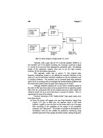
CHAPTER 7
Longitudinal Sensing and Control
Systems
Longitudinal sensing and control systems address situations pertaining to the for
-
ward and rearward movement of the vehicle. Drivers are assisted in perceiving and
responding to obstacles, traffic, and road conditions to avoid crashes.
When parking, basic rear sensing systems help the driver avoid minor bumps
and scratches, while more advanced systems are expected to have the perceptiveness
to detect dangerous situations, such as small children out of view of the driver. On
the open road, the driver’s perception is enhanced through systems such as night
vision and adaptive headlights. Beginning with ACC, forward sensing systems help
drivers perceive the situation ahead of the vehicle to assist in following other traffic
as well as in avoiding crashes.
In fact, forward sensing systems build upon one another. ACC constitutes the
initial foray into forward sensing, which opens up the possibility of using the ACC
sensor for forward collision warning and precharging of the brakes when a colli-
sion is imminent. Higher performance forward sensors support active braking to
mitigate crashes, with the eventual possibility of avoiding most forward crashes
altogether.
Forward collision countermeasures have actually been with us since the late
1980s, starting with systems on heavy trucks. Automotive systems for convenience
(i.e., ACC) came along in 1997, with safety-focused systems being introduced only
recently. There is also interest in equipping transit buses with these collision coun
-
termeasures. While the business case for transit buses may not be strong in general,
just one tragedy in a city can spur equipping an entire fleet.
The net effect of the proliferation of these forward collision countermeasures is
that severe crashes will decrease dramatically in coming years. Drivers will have an
earlier awareness of a potential crash situation and can respond sooner. Forward
crashes in general will decrease as well, but at a slower pace.
Another quite challenging and important area is the detection of pedestrians in
the forward path of the vehicle. Pedestrian detection is challenging due to the com
-
plex road scene in urban areas and difficulty in predicting pedestrian movements
that may be hazardous. Significant progress is being made in this field, however,
and recent progress is described.
Examining the applications list in Chapter 3, we can extract quite a number of
applications that rely upon longitudinal sensing. These are listed here, in the order
in which they will be addressed in this chapter:
121