Machinery Components Maintenance And Repair Episode 1 Part 3 ppsx
Bạn đang xem bản rút gọn của tài liệu. Xem và tải ngay bản đầy đủ của tài liệu tại đây (310.25 KB, 25 trang )
•
Resolve deviations from plan
•
Verify machinery alignment
•
Supervise test runs
•
Restart per startup instructions
Mechanical Supervisors/Planners
Planners, and also mechanical and maintenance supervisors provide
machinery related data and support to the senior machinery specialist and
turbotrain T/A engineers involved in planning and execution of turbotrain
turnarounds.
Again, nine months before the scheduled shutdown for a major
machinery T/A, planners and mechanical supervisors will be given
initial guidance on anticipated duties and responsibilities prior to
and during the actual T/A. From then on, typical action and timing
would be:
Nine Months Before T/A:
•
Maintenance personnel forward machinery-related work lists to
senior machinery specialist for review
•
The most probable work zone outline (see pages 394–400, Volume I
third edition, 1998) is drawn up and forwarded to the senior machin-
ery specialist
•
The mechanical supervisors instruct the spare parts coordinator to
assemble up-to-date tabulation of spare parts presently on hand for
major machinery trains. After review, they forward the tabulation to
the senior machinery specialist.
Eight Months Before T/A:
•
The spare parts coordinator and maintenance personnel receive the
senior machinery specialist’s request to:
1. Place a “hold” on selected parts
2. Order additional spare parts
In response, they issue purchase orders for additional replacement
parts.
•
Next, maintenance supervisors commence dimensional checking
of selected (existing) spare parts per request made by the senior
machinery specialist. The results should be documented within eight
days.
•
Dimensional checking has frequently shown serious discrepancies in
parts designation, dimensional configurations, and tolerances. These
must be identified early if a smooth turnaround is to result.
40 Machinery Component Maintenance and Repair
Six Months Before T/A:
•
Maintenance personnel arrange for vendor assistance
•
Maintenance personnel also work up a more definitive work zone
arrangement and commence tabulation of detailed work list for each
zone
•
Maintenance or technical department personnel witness check bal-
ancing of major turbomachinery rotors
•
Assemble tools and identify missing tools
•
Arrange for scaffolding, etc.
•
Forward data to senior machinery specialist regarding status of spare
parts ordered six months earlier
•
The planner should now provide final work zone arrangement and
detailed work list for each
One month before T/A, maintenance planners or mechanical supervisors
provide bar chart diagrams for machinery-related T/A work.
•
They participate in a meeting with the senior machinery specialist
and designated turbotrain T/A engineers
One week before T/A, mechanical supervisors commence meeting with
designated turbotrain T/A engineers for briefings on matters relating to
machinery work.
Specific Preparation and Planning
When preparing for an overhaul of a major piece of turbomachinery,
it is important to know as much as possible about the machine and why
it needs to be taken out of service. There are several obvious sources
of information, including the operating and maintenance personnel,
the equipment file folder and the vibration history record. If sufficient
information is not found in the file folder, which is all too often the
case, this fact should reinforce the resolve to do a proper job of docu-
menting the planned overhaul in a special manual or “machinery T/A
package.”
Before proceeding, one question usually arises: Is a complete overhaul
really necessary? To properly answer this question, you will need to eval-
uate the symptoms. Has the vibration steadily increased over a long period
of time or have you witnessed a step change? What does an analysis of
the vibration signature reveal? Has the performance gradually fallen off
or taken a dramatic drop? Problems such as a locked gear coupling or
soluble deposits inside the machine can sometimes be corrected without
opening the machine and at a considerable savings of time and effort.
Maintenance Organization and Control for Multi-Plant Corporations 41
Another obvious source of information is the manufacturer’s manual.
The good ones provide detailed, step-by-step instructions with clear illus-
trations; others assume prior knowledge or place undue reliance on the
manufacturer’s service representative. Consequently, it is prudent to
develop procedures, installation instructions, or even detailed commis-
sioning instructions for inclusion in the turnaround package. See Figure
2-6 for typical requirements.
Since a detailed manual is often too bulky for constant reference, we
might reduce portions of it to a critical item list. Certain steps, clearances,
and methods are vital to doing a good job. These items should be sum-
marized and kept for ready reference during the course of the overhaul.
In fact, one complete turnaround package should be on the compressor
platform and should be used while the job is in progress.
It is important to assign the responsibility for the overhaul to one person
so that conflicting positions do not occur. As indicated earlier, we recom-
mend the appointment of a turbotrain T/A engineer to oversee the job and
believe that all decisions and compromises should be made by him. He
should be responsible for the engineering coverage, interface with the
maintenance and operating departments, interface between user company
and original equipment manufacturer, and for documenting the overhaul.
It is a responsible assignment, one that requires judgment, maturity, and
initiative on the part of the engineer. It is strongly recommended that the
turbotrain T/A engineer assume responsibility for the development of data
packages and checklists, some of which are shown later in sample form,
but which must of course be adapted to fit a specific machine or turn-
around situation.
Safety
Work safely. Be sure all power is off, blinds in, purging procedures
followed, etc. A prework safety item checklist is strongly recommended,
as is a list of all blind locations. The latter item is important at the begin-
ning of a job to ensure all necessary lines are secure, and, at the end of
the job, to check off the removal of all installed blinds. Failure to install
or remove a blind at the appropriate time could lead to a disaster.
Account for tarps and “welding blankets.” These are known to have
been left in piping, only to later be ingested into equipment. The conse-
quences of these oversights have ranged from costly to catastrophic.
It is important to establish teamwork and proper communication among
the operations, safety, engineering, and maintenance personnel at the start
of the job so that each can fulfill his role in the total effort. A list of key
42 Machinery Component Maintenance and Repair
players and where or how they can be reached during the overhaul period
should be made available at the start of the job.
Planning
If this is a planned overhaul, as opposed to a forced outage, so much
the better. Take full advantage of the planning period to make a visual
inspection of the machine before the shutdown. Pay particular attention to
the condition of the foundation, anchor bolts, piping, instruments, and
look for leaks. It is a good idea to keep an “evergreen” list of required
maintenance items in the equipment folder. Encourage personnel who fre-
quently go on the machinery deck to make written note of any problems.
Take a final check of vibration, performance, alignment, and mechani-
cal health data just prior to the shutdown. A small shirt-pocket size tape
recorder or palm-size computer with voice recognition software is partic-
ularly useful to record notes; it leaves the hands free to manipulate instru-
ments, etc. The data can then be transferred to spreadsheets back in the
office. If you are working a forced outage, the most recent set of data will
have to do. Compare the most recent information to previous readings
and develop a list of anticipated problems. Translate all of this informa-
tion into a detailed job plan per Figure 2-7, or as available from CMMS
software programs.
In our experience, machines are normally shut down for overhaul due
to fouling (restricted performance); excessive vibration (ingestion of a
liquid slug, a loose piece of hardware, the failure of a mechanical com-
ponent or misalignment); misoperation (surge, lube oil supply failure,
etc.); or when the whole process unit is shut down for a T/A. In general,
we do not open machines that are running satisfactorily just for inspec-
tion. At every convenient opportunity one should inspect externally
accessible components, such as couplings, and also check items such
as rotor float and shaft alignment, and all tripping devices and general
instrumentation.
In the case of steam turbines, the overspeed trip bolt and the steam trip
and throttle valve have proven to be the least reliable—and yet most
important—safety devices in the train. A check of these two components
is mandatory during major shutdowns, and checks should be made at
every other opportunity. We believe these are the most important checks
performed during a shutdown. In addition, one should “exercise” the trip
and throttle valve weekly by moving the stem in and out manually several
turns on the hand wheel to preclude the buildup of deposits that would
prevent the machine from tripping during a shutdown condition.
Maintenance Organization and Control for Multi-Plant Corporations 43
44 Machinery Component Maintenance and Repair
Figure 2-7. Sample sheet of turbomachinery turnaround job plan.
Consider an example of the penalty associated with the failure of a trip
circuit at one plant. A 10,000 horsepower, steam turbine-driven com-
pressor train failed to trip during a condition which had caused the com-
pressor to fill with liquid while at full speed. The resulting loads led to
catastrophic failure of both the compressor and coupling and allowed the
steam turbine to overspeed to destruction. The repair bill for parts and
labor came to well over $1,000,000. The cause of the wreck was eventu-
ally traced to the buildup of deposits on a brass piston in the hydraulic
shutdown system which was in a hot dead-ended oil circuit. The heat
caused the oil to decompose over a long period of time, in turn causing
the piston to stick. As a result, the plant now checks trip circuits more fre-
quently. They have also installed redundant electronic backup trip devices
on large equipment trains.
Spare Parts
The time to check spare parts is not in the middle of the night follow-
ing an emergency phone call from the operating department manager.
Most large companies have some degree of computer control on the ware-
housing and reordering of spare parts. But how many times have you been
lied to by a computer? There is no substitute for a hands-on check of parts
by a knowledgeable individual. Part numbers must be checked because
the item on the shelf is not necessarily the one you expected to find.
Many major plants allocate special boxes to major machinery spare
parts storage. The boxes have individual compartments for labyrinths,
seals, bearings, etc. A list on the lid details all parts inside, their location
in the box, the manufacturer’s part number and the company’s stock
number. Once filled, the box is sealed and stored in the usual manner.
During an overhaul, the box is taken to the field and some or all of the
parts consumed. The box is then returned to the warehouse with a list of
consumed parts to be replaced. A computerized call-file system should be
used to keep tabs on rotors that are out of the plant for repairs and deliv-
ery of other critical spare parts.
When checking spare parts, it is important to recognize that not only
must the part be the right size, it also must be in good condition. Handling
and improper storage, as well as deterioration with time, are a few of the
hazards associated with a warehousing operation. A nicked O-ring or a
carbon seal face out of flatness could require a second shutdown to correct
the problem. The use of an optical flat, a set of micrometers, and a know-
ledgeable pair of eyes can be invaluable in detecting a defective part.
Also, remember that just because the part came from the factory,
doesn’t necessarily mean it is the right one for your machine. While
Maintenance Organization and Control for Multi-Plant Corporations 45
equipment manufacturers have various quality control procedures, they
too rely on human beings, and errors do occur. In addition, some parts
have a finite shelf life (case split line sealant is an example) and must be
fresh when the time comes to use them.
This is also the time to check on the availability of special (custom
fabricated) tools. These should be kept in a separate box, inventoried at
regular intervals, and generally treated as a valuable spare part or essen-
tial resource. Delaying an overhaul for several hours to fabricate a special
seal nut wrench is time and money wasted. Alignment brackets and cou-
pling “solo” plates fall into this category.
The Spare Rotor
By far the most critical single spare part is the spare rotor. Most com-
panies purchase the spare rotor at the time the machine is purchased and
require a four-hour mechanical test to ensure integrity prior to acceptance
of the machine. It would be prudent to check the spare rotor after every
transport event. This means a runout or rotor bow check upon receipt from
the manufacturer, as well as a check of the preservative used for long-term
storage. A runout check is also performed at the time the rotor is check-
balanced and prepared for installation. Be sure to obtain a rotor runout
diagram and balance report at that time.
Rotors of all sizes are often stored vertically in a remote temperature
controlled storage building as shown in Figure 2-8. If a user opts for hor-
izontal storage, the rotors must be placed on substantial stands and should
be turned 180° two to four times a year. These stands must employ rollers
rather than lead or Teflon
®
material at the support points. In cases where
sheet Teflon
®
is placed between the storage cradle and the rotor there is
some risk of filling the microscopic pores of a shaft journal which could
prevent the formation of an adequate oil film on startup and could cause
bearing failure.
Rotors must, of course, be handled with great care. Nylon slings should
be used to prevent damage and all lifts should be made under the watch-
ful eye of a competent individual. Never hesitate to call a halt to a lifting
operation if the possibility of damage exists. You are being paid to look
out for the company’s interests and a rotor worth $200,000 to $1,000,000
or more is well worth a lot of care and concern. The rotor must be slung
so that it is horizontal and its center of gravity is located under the hook,
and it must be moved very slowly. Consider your vibration monitoring
probes when removing a rotor from storage in preparation for installation.
Record the rotor’s serial number and verify that it is not positioned in a
way that will interfere with a thrust position eddy current probe. Some
46 Machinery Component Maintenance and Repair
users also report success with degaussing and/or micropeening techniques
to minimize electrical runout in the areas viewed by the radial eddy current
probes. Others report some success rolling the rotor on a balance stand
with the areas under the probes directly on the balance rollers.
Diagrams
A critical dimension diagram (Figure 2-9) and associated tabular
records (Figures 2-10 through 2-12) have proven invaluable in the middle
of the night during a complicated overhaul. A critical dimension diagram
is a tabulation or sketch recording critical data such as bearing and
labyrinth clearances, rotor float, seal clearances, coupling advance, cou-
pling bolt torque, etc. The document must clearly show maximum and
Maintenance Organization and Control for Multi-Plant Corporations 47
Figure 2-8. Spare rotors must be removed from storage and cleaned and inspected prior
to the turnaround.
minimum values, as well as spaces for “as found” and “as left” conditions.
Any warning notes such as internal bolts, left-hand threads, or other crit-
ical steps should be clearly flagged on this sheet. Clearances should be
properly labeled as to diametral or radial, metric or English units, to avoid
confusion.
An alignment diagram, as shown in the chapter on machinery align-
ment, complete with estimated thermal growth and desired readings, is
mandatory. This should be available from previous alignment work. If it
is not, and if reverse dial indicator alignment techniques are not well
known and practiced at your plant, we would strongly recommend imple-
mentation of such a program. The techniques and procedures have been
the subject of many papers.
The records and documents described thus far have proven to be time
saving and hence, money saving, and are well worth the effort. Another
useful item involves preplanning the allowable limits on the desired shaft
position. It is impractical to expect the field crew to place a compressor
or turbine in the exact position as shown on the alignment graph. If allow-
able limits are known in advance (not necessarily by the field crew, but by
48 Machinery Component Maintenance and Repair
Figure 2-9. Critical dimension diagram for centrifugal compressor.
the engineer in charge of the overhaul), a decision or compromise can be
made in a rational manner depending on need for the machine and time
available to achieve acceptable alignment. Under no circumstances should
alignment be compromised beyond a few thousandths off the desired posi-
tion nor excessive pipe strain be permitted on the machine. The search for
absolute perfection will, however, generally be rewarded with time con-
suming frustration and an ultimate compromise in any case.
Miscellaneous Items
Any good shutdown/overhaul plan should include an inspection of aux-
iliary components. During the overhaul period is the time to clean lube
Maintenance Organization and Control for Multi-Plant Corporations 49
Figure 2-10. Critical data tabulation.
oil coolers, replace filters, overhaul lube oil pumps, etc. But beware of
introducing dirt into the system. Many a clean lube set and newly over-
hauled machine have been damaged by a few seconds of careless main-
tenance activity.
The instrumentation associated with the machinery train should also be
checked and calibrated. Again, a list and adequate record keeping prac-
50 Machinery Component Maintenance and Repair
Figure 2-11. Critical dimension tabulation.
tices are a must. The list should include all set points and complete infor-
mation on any rebuilt instruments placed back in service. The engineer in
charge of the overhaul will normally delegate this task to the instrument
group after collaborating on the list with this group and the operating
department to pinpoint any troublesome items. Key shutdown instruments
such as low oil pressure and high discharge temperature should, of course,
receive as accurate a test as practical.
The Factory Serviceperson
Most machinery manufacturers’ manuals recommend the use of a
factory serviceperson. It is most important to know whom you are getting
and what his qualifications are. One maintenance manager had the un-
settling experience of shaking the hand of a serviceman from a major
Maintenance Organization and Control for Multi-Plant Corporations 51
Figure 2-12. Clearance tabulation.
supplier of gas turbines who then mentioned that he normally worked on
steam turbines and this would be his first gas turbine. The point is, after
several years in the field, assuming continuity of plant personnel, the user
many times will know more about the machine than its manufacturer.
Factory field servicemen lead a rough life: 16–20 hour or more shifts
are common, as well as frequently being away from home. Attrition
is high. You will find some very good and some very bad ones. Keep
a list of those to invite back, as well as those you would rather not use
again.
The Overhaul
During the course of the overhaul, it is very important to keep track of
the job on an hour-to-hour, shift-to-shift basis. Companies using a shift
log or diary for this purpose have found it to be an invaluable communi-
cations tool. The critical dimension diagram and the alignment diagram
should likewise be kept available for ready reference, as should the turn-
around book or T/A package mentioned earlier.
The use of a good quality camera and a capable photographer to doc-
ument details of the overhaul is strongly recommended. A good T/A
package will include a pictorial sequence of assembly and disassembly
steps, as we will show later. After all, if you do a good job, it will be five
to eight years or longer before anyone sees the inside of the machine again.
Be sure to use a digital camera, and keep in mind the merits of video
taping to provide training films for the maintenance department.
Before the actual shutdown of the machine is the time to take a final
set of hot alignment data, if such a program is currently in use at your
plant. There are, of course, several accepted methods for checking hot
alignment. One is the use of eddy current probes, either inside the cou-
pling guard or on the machine cases. A second is the optical method using
a transit and targets on the machine train. A third is the use of a telescoping
measuring rod with reference points on each machine and benchmarks on
the foundation. A fourth and most up-to-date method may involve laser
optics.
If you don’t currently check running hot alignment (as opposed to the
old method requiring a shutdown/alignment check, which has proven to
be both inaccurate and unreliable), we would strongly recommend evalu-
ating the various systems to see which one best fits your needs. As with
reverse dial indicator alignment, a good hot alignment method can be a
real money saver. Several items should be checked after the machine has
stopped turning, but before the actual disassembly begins:
52 Machinery Component Maintenance and Repair
1. The coupling: If it is a gear coupling, is it free to move on the gear
teeth? Have you considered upgrading to a contoured diaphragm
coupling?
2. Look for broken coupling bolts. Broken bolts can indicate several
problems, the most likely being incorrect bolt torque on installation,
the wrong bolt material, or mismachined coupling flanges.
3. Get a sample of coupling grease, if a grease-packed coupling is used.
4. When removing the coupling, remember to turn the nuts and prevent
the bolt head from turning so as to avoid wearing the body-fitted
bolts. In a double-keyed coupling, be sure to check that the keys are
marked as to their location.
5. Be sure to keep the coupling bolts and nuts together as individual
assemblies. Do not plan to reuse the nuts more than twice. If any
doubt exists in this area, a new set of match-weighed nut and bolt
assemblies is cheap insurance.
6. Check and record rotor float within the thrust bearings, and note also
the spacing between shaft ends.
7. Check the total rotor float with the thrust bearing removed, and note
the rotor position relative to the machine case. Check nozzle stand-
off in the case of a steam turbine, or position between diaphragms
in the case of a compressor.
8. When removing the thrust bearing, be sure to measure and tag any
thrust shims used for thickness and location (inboard or outboard).
Opening the Machine
Before actually opening a major piece of machinery, take time to review
the critical steps in the operation. Attempting to remove an upper half
casing without first removing internal (nonexposed) bolting or lifting the
casing without using guide pins can result in a much longer and more
expensive overhaul. Be especially careful when opening lube oil lines. The
loss of a flow control orifice or the introduction of dirt into the system can
cause serious problems during the machine startup.
As the machine comes apart, take lots of pictures, make written notes,
and/or use a handheld computer or tape recorder to document what you
see. It’s amazing how much detail will be lost and how difficult it is to
accurately reconstruct events hours or days—let alone years—after they
have occurred.
One major petrochemical company operates four identical 20,000
horsepower steam turbines which, due to a series of blade problems, had
to be opened a total of 31 times in an eight-year period. They recognize
Maintenance Organization and Control for Multi-Plant Corporations 53
the importance of rotor charts to keep track of rotor movements and mod-
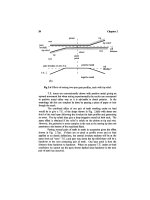
ifications, as shown in Figure 2-13. When the first blade in the first rotor
failed, it was not apparent that they were in for such a lengthy problem.
The rotor movement chart was laboriously constructed from memory
when they were halfway into the program and had added a sixth rotor to
the system (four installed and two spares).
If you plan to remove compressor diaphragms, be sure to match mark
them as to their position in the case. Inadvertent mixing of inlet guide
vanes could alter machine performance! Be careful to stone down any
match marks which are placed in a machined area, such as the casing split
line. When the top half of a horizontally split compressor is removed, it
is a good idea to position the rotor with its thrust bearing as it was before
shutdown and check to see if the impellers are centered with the diffuser
flow passages.
Inspection
As the machine is being opened, pay particular attention to visible
deposits. On machined sealing surfaces you may find telltale tracks of a
leak or wire drawing. Such leaks may indicate a need to check the flat-
ness and fit of the surfaces with lead wire or Plasti-Gage
®
, or simply better
54 Machinery Component Maintenance and Repair
Figure 2-13. Rotor history chart.
attention to bolt torquing requirements. Fouling inside the flow passages
of the machine will likely not be distributed uniformly from one end to
another. In a compressor, the gas will get hotter with each successive stage.
With some gases this will bake the deposits in the latter stages;
with other gases, heavy, wet deposits will form in the first stages of the
machine. Get a sample of the deposits to determine, first, what they are
in order to see if they can be eliminated from the process. Failing that,
test to see if they can be dissolved in some suitable solvent, for either
on-line or off-line washing, in order to delay a subsequent machine over-
haul. While compressor manufacturers shy away from on-line full-speed
washing, knowledgeable users have had very good experiences with both
this technique and with off-line washing when the machine is slow rolled
while half full of the wash liquid. When choosing a wash fluid be sure it
is compatible with all components in the machine, such as O-rings, as well
as the process. On-line abrasive cleaning with walnut hulls, etc., has found
wide acceptance with gas turbine users, but is not without its problems.
Plugged orifices, airbleed passages, and the like are common. The total
subject of on-line or off-line cleaning is beyond the scope of this text, but
it is well worth considering in specific situations as it is a real time and
money saver.
The bearings, journals, and seals should be visually checked for signs
of distress. One frequent problem has been that of babbitt fatigue. While
the aftermarket has been offering bearings with babbitting less than
0.010 in. thick for a number of years, some machinery manufacturers have
resisted change in this area. Nevertheless, industry experience with thin
babbitt bearings has been excellent to date.
Labyrinths can also tell a story which needs to be read and analyzed.
Deep grooves in the impellers or shaft spacers are indications of a shaft
excursion at some time in the operating cycle. Worn or corroded labyrinths
indicate loss of efficiency, and, if found over the balance piston, could
lead to a thrust bearing failure. As with bearings, new materials, such as
Vespel
®
high-performance graphite-filled polymers able to combat the
corrosion problem, are now coming into the after-market. Rubs could
indicate misoperation, such as running at or near a rotor critical speed or
in surge; a rotor dynamics problem; a thermal bow, or similar difficulty.
Observations regarding location, depth, and distribution of the rubs are
the keys to a proper analysis.
Cleaning
When cleaning fouled components—rotors and diaphragms, etc.—
make sure the work is done in a remote location. Sand or nut hulls used
Maintenance Organization and Control for Multi-Plant Corporations 55
for this purpose will usually find a way of invading the wrong parts of the
machine, such as bearings and seals. The rotor should be carefully checked
at this time for debris lodged in the gas passages. We know of instances
where a rag or piece of metal was jammed in an inaccessible place in an
impeller. The use of a small dental mirror and a thorough inspection by
hand can reveal much of this debris.
It is fairly common practice to inspect a rotor using magnetic particle
or dye penetrant techniques. This is a strongly recommended step; it can
turn up defects which could otherwise prove to be highly damaging during
a subsequent running period. In one such instance we uncovered an unde-
sirable manufacturing technique which has been practiced for many years.
The magnetic particle and subsequent dye penetrant inspections showed
several cracks around the eye of the fifth stage impeller in a multistage
barrel compressor rotor installed in relatively clean hydrogen service. Up
to this point the overhaul had been a routine matter, but now took on far
more serious implications. It seems that this particular compressor man-
ufacturer had been in the habit of overspeed testing impellers and then
trimming the eye labyrinth area to size, thus weakening the most critical
structural area of the impeller. The explanation given (to compensate for
bore stretch during overspeed) is, of course, unacceptable. Most manu-
facturers will now readily guarantee maximum allowable expansion in the
diameter of the eye of an impeller as a function of the diameter before
the overspeed test. This is the only acceptable way to buy compressor
impellers, either as part of a new machine or as a replacement part.
Reassembly
Once the machine has been opened and all parts cleaned and inspected,
the reassembly procedure can begin. There are many critical phases
involved with this operation, one of the most important being care in han-
dling the rotor. Large heavy rotors (over approximately 2,500lbs) require
special handling and, in some cases, special guide fixtures should be fab-
ricated to avoid damaging components. This is particularly necessary with
gas turbines which have many exposed, fragile parts. A solid rotor cradle
is also a very necessary item. Do not jeopardize your most valuable spare
part by failing to protect it during the course of an overhaul or during
transit to or from the storage warehouse.
When fitting housings and other components with multiple O-rings in
blind areas, we have found that it is usually beneficial to first remove the
O-rings and fit the housing by hand to check the alignment of the assem-
bly. Blind dowels or concealed shims can be located in this manner with
pencil marks. The O-ring fits should be touched lightly with Grade 600
56 Machinery Component Maintenance and Repair
wet or dry emery paper to remove any burrs, and then checked carefully
by hand. Lubricate the O-rings with a suitable grease or oil. A cut O-ring,
worth very little in itself, can bear heavily on the success of an overhaul.
Bearing clearance is one of the most important checks during reassem-
bly. We have found that after several years of operation, the pads of a tilting
pad journal bearing will wear small depressions in the support ring or
housing which can open the clearance beyond specifications. Also,
replacement pads may not be within tolerance. The only proper way to
check bearing clearance with this type of bearing is by using a mandrel
the size of the journal and a flat plate. The clearance in a sleeve-type
journal bearing can be checked with Plasti-Gage
®
. Be sure to torque the
bearing cap bolts correctly or you may get a false reading.
When assembling bearings be sure the anti-rotation dowels are in place
and look to be sure the oil dam (if used in that particular bearing) is in
the correct direction of rotation. Some of these steps will sound obvious,
but each one results from a problem experienced in the field. It is also
useful to check the alignment of oil supply holes in the housing with oil
feed grooves in the bearing. For want of a
3
/
8
-in, groove in the housing of
a replacement bearing, one user lost a high speed shaft and impeller
assembly in a plant air compressor package.
Before the upper half of the casing of a horizontally split machine is
bolted in place, a final rotor mid-span bow check is recommended. This
is particularly useful if you, as the responsible engineer on an overhaul,
have not been able to personally witness all rotor movements during the
course of the job.
Coupling hub fit is another area requiring consideration. The assump-
tion that the taper is correct provides a false sense of security. By lightly
bluing the shaft and transferring the bluing to the coupling bore, the fit
can be properly checked. It is prudent to require at least 85 percent contact.
If the contact pattern is not acceptable, the question of whether to lap
or not to lap needs to be addressed. We will not lap using the coupling
half for obvious reasons, but will lap using a ring and plug gauge set.
The advance of the coupling on the taper must be correct and should be
witnessed and recorded by a knowledgeable individual. Coupling bolts
must be torqued to the coupling manufacturer’s specifications as the
clamping force, not the bolt body, is generally the means of transmitting
the torque.
As the machine goes back together, fill in the information in the criti-
cal dimension diagram. Labyrinth and bearing clearances, total rotor float,
thrust clearance, coupling advance, bolt torque, etc., should all be mea-
sured and logged. Shaft alignment and cold baseline data for comparison
with hot growth data taken after startup should also be logged on the
appropriate sheet. Remember to check the shaft end gap, as not all rotors
Maintenance Organization and Control for Multi-Plant Corporations 57
are created equal and the wrong dimension could damage your coupling.
When leaning into an open machine, it is well to remember to remove all
loose objects from shirt pockets!
There are some other checks which may or may not have been incor-
porated in the critical dimension diagram, most notable of them being
whether the rotor is free to turn and whether oil is flowing to and from
the proper places. This latter item can be viewed just prior to bolting
bearing caps or covers in place, assuming the oil lines have been recon-
nected. On some machines with internal oil tubing, it is possible to have
oil flow showing in the main oil drain sight flow indicator while no oil is
reaching the bearings or seals!
Documenting What You’ve Done
Following the overhaul, the startup will need to be monitored. If you
don’t have a fixed-base monitoring system, use a portable real time ana-
lyzer and a modern recorder to obtain baseline vibration data for com-
parison with previous operating information. Hot alignment readings
can usually be taken several hours after startup. Machine performance will
normally be checked after the process has stabilized which, on some
machines, can be as long as several days after startup. All of this infor-
mation provides a very useful check on the success of the overhaul and
should be taken at the outset of a run and not delayed until a “convenient”
time several weeks from startup.
As soon as the machine is operating satisfactorily, do the paper work,
i.e., update your computer log. Many engineers shy away from this duty
and use the excuse of day-to-day business pressures to delay or even forget
this very necessary chore. While the events are still fresh in your mind,
sit down and finish the job. In documenting an equipment overhaul, con-
sider using the following format:
1. Basic Machine Data—A brief description of the machine, includ-
ing manufacturer, model number, number of stages and other phys-
ical parameters, serial number, date purchased, date of last overhaul
and reason for current overhaul.
2. Performance, Vibration, and Mechanical Health Data—A compar-
ison of pre- and post-overhaul levels. Performance and vibration
data for the train, including process flow, pressure and temperature,
machine case, and eddy current probe vibration levels, as well as
oil supply pressure, temperature, and oil return temperature. The
performance data should be sufficient to accurately assess the
machine’s condition. Calibrated instruments are required.
58 Machinery Component Maintenance and Repair
3. Spare Parts—A complete list of spare parts for the machine, as well
as a list of parts actually consumed. Include machine manufac-
turer’s part number, as well as company warehouse stock number.
4. Critical Dimension Diagram—Complete with factory specifica-
tions, as-found dimensions (logged during disassembly), and as-
overhauled dimensions. This information must include items such
as total rotor float, thrust clearance, rotor position within the total
float, labyrinth clearance, radial bearing clearance, nozzle stand-
off, coupling bluing check, and coupling advance.
5. Rotor run-out diagram and balance report.
6. Shaft Alignment Diagram—A shaft alignment diagram showing
desired readings based on anticipated thermal growth data, “as
found” readings (prior to overhaul), “as left” readings after over-
haul, and actual measured thermal growth data.
7. Photographs of the overhaul.
8. A discussion of the overhaul. Refer to appropriate photographs
throughout.
9. Recommendations:
•
For future overhauls
•
For reconditioning worn but reusable parts
•
For on-line cleaning, if applicable
•
For redesigned parts, if applicable
10. Shift logs and backup data as required.
In writing a report, decide what went right and what went wrong. Fully
identify the causes in each case so that your successor can benefit from
your experiences. Send a list of spare parts used in the overhaul to the
warehouse controller. While you hope you won’t need parts in a hurry,
don’t bet on it! Decide if you plan to invite the factory serviceperson back
for a subsequent overhaul. In either case, put his name on your report so
no confusion exists on this point. Go back to the machine manual and
make notes in the margin on any errors that may have appeared in the
printed material.
Nonstandard Parts
Once a new machine has operated for a year, it is well to remember that
the guarantee has probably elapsed. In addition, bear in mind that the orig-
inal equipment manufacturer’s parts were generally a design compromise
which took into account a competitive marketplace and existing, available
designs in the manufacturer’s shop. Any parts that fail to stand up should
not necessarily be replaced by standard parts. There are many excellent
Maintenance Organization and Control for Multi-Plant Corporations 59
aftermarket manufacturers of components and many specialized tools
such as multiplane milling machines and overspeed spin pits for individ-
ual components. Aerospace technology and materials are beginning to
filter down to the aftermarket also. None of the above should be construed
as an indictment of the equipment manufacturer, but when his spare part
pricing, policies, and failure to solve design problems mount to a point
where it becomes necessary to put properly engineered aftermarket
components into a machine, do not hesitate to do what is best for your
company.
60 Machinery Component Maintenance and Repair
Chapter 3
Machinery Foundations and
Grouting*
What’s an Epoxy?
According to the Handbook of Epoxy Resins,
1
the term epoxy refers to
a chemical group consisting of an oxygen atom bonded with two carbon
atoms already united in some other way. The simplest epoxy is a three-
membered ring. There is no universal agreement on the nomenclature of
the three-membered ring. There is division even on the term epoxy itself—
the Europeans generally prefer the term epoxide, which is doubtless more
correct than the American epoxy.
In addition to providing a history of the development of epoxy resins,
the handbook states that the resins are prepared commercially thus:
1. By dehydrohalogenation of the chlorohydrin prepared by the reac-
tion of epichlorohydrin with a suitable di- or polyhydroxyl material
or other active-hydrogen-containing molecule.
2. By the reaction of olefins with oxygen-containing compounds such
as peroxides or peracids.
3. By the dehydrohalogenation of chlorohydrins prepared by routes
other than by route 1.
Dozens of distinct types of resins are commercially available, and the
term epoxy resin is generic. It now applies to a wide family of materials.
Both solid and liquid resins are available.
61
* E. M. Renfro, P. E. Adhesive Services Company, Houston, Texas.
There are other liquid resins such as phenolics, polyesters, acrylics, etc.,
which cure in similar fashion, but the epoxy resins possess a rather unique
combination of properties. The liquid resins and their curing agents form
low-viscosity, easy-to-modify systems. They can cure at room tempera-
tures, without the addition of external heat and they cure without releas-
ing by-products. They have low shrinkage compared to other systems.
They have unusually high bond strengths, excellent chemical resistance,
high abrasion resistance, and good electrical insulation properties.
The basic properties can be modified by blending resin types, by selec-
tion of curing agents (hardeners), the addition of modifiers, and by adding
fillers.
Perhaps the most valuable single property of the epoxy resins is their
ability to cure, thus converting from liquids to tough, hard solids. This is
accomplished by the addition of a curing agent. Some agents promote
curing by catalytic action, while others participate directly in the reaction
and become part of the resin chain. Depending upon the particular agent,
curing may be accomplished at room temperature with heat produced by
exothermic reaction, or may require application of external heat. The
epoxies will react with over 50 different chemical groupings, but the basic
curing agents employed in the epoxy resin technology are Lewis bases,
inorganic bases, primary and secondary amines, and amides.
An entire spectrum of properties can be obtained in a cured epoxy resin
system by careful selection of resins, careful selection of curing agents,
varying the ratio of resin to curing agent and by including additives or
fillers. The resins and curing agents, themselves, may even be blends. As
an illustration of the spectrum of obtainable properties, a cured epoxy
system may be as soft as a rubber ball or so hard that it will shatter when
dropped. Epoxies can be formulated to be either sticky or tack free. They
can be formulated to either melt or char when heated; to release tremen-
dous amounts of heat when curing or they may require heat for curing; to
bond tenaciously to sandblasted steel, even under cryogenic conditions, or
have relatively little bond; or to be either tough or friable.
Epoxy Grouts
Grout is a broad term covering all of those materials used in a wide
variety of applications which include clinking for cracks, fissures, or cav-
ities; a mortar for tile and other masonry; a support for column footings;
a sealant for built-in vessels; or a mortar for setting heavy machinery. This
text, however, is concerned with those epoxy-based materials used in
setting heavy machinery and in repairing concrete foundations. Specifi-
cations for Portland cement grouting and epoxy grouting of rotating equip-
62 Machinery Component Maintenance and Repair
ment, as well as a checklist for baseplate grouting, can be found in the
appendices at the end of this chapter.
The need for a machinery grout is created by a combination of cir-
cumstances occurring in the construction of foundations. Many of these
circumstances are unfavorable to concrete, thereby complicating its use.
This condition is brought about primarily because it is impossible to pour
a concrete foundation to within the tolerances usually required for preci-
sion leveling and alignment of dynamic equipment. Even if such exact
placement were possible it would be further complicated by the fact that
concrete shrinks while curing.
Furthermore, the laitance or weak surface created when simple concrete
is cast or troweled would not provide sound support for machinery requir-
ing precision alignment. It has therefore become a standard practice in
construction of foundations to pour the concrete to a level slightly above
the desired grade, and after curing, chip away the surface to remove the
laitance. The machinery is then positioned on the foundation, leveled and
aligned to within proper tolerances with the aid of jack screws, wedges,
shims, etc., and the gap grouted in solidly to establish integrity between
the machine base and the concrete foundation below.
When improperly installed machinery breaks loose, the static forces to
which the foundation is subjected do not act alone. Vibratory forces of
high magnitude will also exist. Given enough time, this will usually cause
cracks in the foundation that allow lubricating oil to penetrate deep into
the foundation and proceed to degrade the concrete. It therefore becomes
necessary to repair the cracked foundation, remove or repair oil-soaked
concrete and regrout in order to re-establish the integrity of the system.
Epoxy grouting materials have long been used for these repairs.
The specific use for which grout is intended should be taken into
consideration when evaluating the properties of a prospective grout. It is
equally important to ascertain the conditions under which a manufacturer
obtained his test data.
Some properties contribute to the long service life or performance of a
grout while others facilitate the ease of installation or grout placement. In
evaluating a prospective grout, performance characteristics should take
preference over ease of placement characteristics. These properties are of
key importance:
•
Nonfoaming—Without a doubt, the single most important charac-
teristic of a grout from a performance standpoint is its ability to sta-
bilize and disperse any air introduced with the aggregate or entrained
during normal, nonviolent mixing. Otherwise, a weak, foamy surface
would develop soon after pouring, and be unable to maintain align-
ment. Surface foam can always be eliminated by selecting the proper
Machinery Foundations and Grouting 63
aggregate and maintaining viscosity of the mixed grout with proper
aggregate ratio. This ratio cannot be fixed for all temperature
conditions because the viscosities of the liquid ingredients change
with temperature as do other hydrocarbons. The aggregate ratio will
increase as the temperature of the ingredients becomes higher. Incor-
porating air release agents and surface defoamers in the grout for-
mulations does improve the appearance of the exposed foundation
shoulders, but does not prevent entrapment of air bubbles under the
equipment base. Even with a time lapse between grout mixing and
grout placement, air cannot be properly released because of the
difference in rise rates of various size air bubbles, particularly in
“soupy” mixes.
•
Dimensional Stability—Three causes of dimensional change in
grouts are shrinkage while curing, thermal expansion or contraction
from temperature changes, and stress deformation or creep. Shrink-
age in epoxy grout systems can occur if the formulation contains non-
reactive volatile solvents that can, with time, gradually evaporate
from the grout. This material loss usually results in shrinkage or
cracking. Shrinkage is also theoretically possible in cases where
improper ratio of resin to curing agent exists as a result of dispens-
ing error or as a result of poor or incomplete mixing. Shrinkage is
virtually nonexistent in properly formulated and properly mixed
epoxy grout.
•
Grout Expansion—Thermal expansion coefficients of grouts should
be compared with the rate of thermal expansion of concrete and steel
since it will be sandwiched between the two materials. Concrete and
steel have about the same linear coefficient of thermal expansion.
Unfilled epoxy resin systems expand or contract at about ten times
the rate of concrete and steel. The high rate of expansion of unfilled
epoxy does not cause problems when the epoxy is of a nonbrittle for-
mulation and is present only in thin films, as in pressure grouting.
When aggregate is added to the liquid epoxy/curing agent mixture to
form a mortar, the linear coefficient of thermal expansion can be
reduced to the range of 1.2–1.4 ¥ 10
-5
in./in.°F, or about twice the
rate for concrete or steel. When reviewing properties of a grout,
compressive strengths should be considered along with the modulus
of elasticity (the slope of the stress-strain curve). Generally, the
more rigid the material, the steeper the slope and the higher the
modulus of elasticity. Rubber, for example, is elastic according to
the lay definition, but relatively nonelastic according to the technical
definition.
•
Strength—There are several methods of measuring strength of a
grout. It can be measured under compression, tension, impact, and
64 Machinery Component Maintenance and Repair