Machinery Components Maintenance And Repair Episode 1 Part 8 pdf
Bạn đang xem bản rút gọn của tài liệu. Xem và tải ngay bản đầy đủ của tài liệu tại đây (343.63 KB, 25 trang )
Process Machinery Piping
165
(Text continued from page 157)
All bolt torque values are based on the use of new nuts (ASTM A194,
GR 2H) and new bolts (ASTM A193, GR 87) of proper design, acceptable quality, and approved materials of construction as well as metallurgy.
It is also required that two hardened steel washers be used under the head
of each nut and that a non–metallic-based lubricant (i.e., oil and graphite)
be used on the nuts, bolts, and washers.
The flanges are assumed to be in good condition and in compliance with
ASME B16.5 specifications. Special attention should be given to seating
surface finish and flatness.
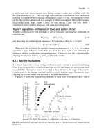
Only torque wrenches that have been calibrated should be used. The
proper bolt tightening pattern must be followed (see Figure 4.6 for proper
bolting pattern) with the desired ultimate torque value arrived at in a
minimum of three equal increments. All bolts in the flange should then be
checked in consecutive order in a counterclockwise direction.
The contact dimensions listed are taken from the inside diameter (ID)
and outside diameter (OD) of the windings, which are different from the
ASME ring gasket dimensions. No provisions have been made in these
tables to account for vibration effects on the bolts. These tables are based
on ambient conditions, without compensation for elevated temperatures.
If conditions different from these exist, we suggest that further analysis
be performed to determine the appropriate torque values.
Gasket Installation
In a flanged connection, all components must be correct to achieve a
seal. The most common cause of leaky gasketed joints is improper installation procedures.
Figure 4-6. Installation sequence for 4-, 8-, and 16-bolt flanges.
166
Machinery Component Maintenance and Repair
Bolting Procedures
•
•
•
•
•
•
•
•
•
Place the gasket on the flange surface to be sealed
Bring the opposing flange into contact with the gasket
Clean the bolts and lubricate them with a quality lubricant, such as
an oil and graphite mixture
Place the bolts into the bolt holes
Finger-tighten the nuts
Follow the bolting sequence in the diagrams above
During the initial tightening sequence, do not tighten any bolts more
than 30 percent of the recommended bolt stress. Doing so will cause
cocking of the flange and the gasket will be crushed
Upon reaching the recommended torque requirements, do a clockwise bolt-to-bolt torque check to make certain that the bolts have
been stressed evenly
Due to creep and stress relaxation, it is essential to pre-stress the bolts
to ensure adequate stress load during operation
Hydrostatic Testing Precautions
If hydrostatic tests are to be performed at pressures higher than those
for which the flange was rated, higher bolt pressures must be applied in
order to get a satisfactory seal under the test conditions.
Use high-strength alloy bolts (ASTM B193 grade B7 is suggested)
during the tests. They may be removed upon completion. Higher stress
values required to seat the gasket during hydrostatic tests at higher than
flange-rated pressures may cause the standard bolts to be stressed beyond
their yield points.
Upon completion of hydrostatic testing, relieve all bolt stress by 50
percent of the allowable stress.
Begin replacing the high-strength alloy bolts (suggested for test conditions) one by one with the standard bolts while maintaining stress on the
gasket.
After replacing all the bolts, follow the tightening procedure recommended in the bolting sequence diagrams (Figure 4-6).
Pre-Stressing Bolts for Thermal Expansion
Bolts should be pre-stressed to compensate for thermal expansion as
well as for relaxation, creep, hydrostatic end pressure, and residual gasket
loads.
Process Machinery Piping
167
A difference in the coefficient of thermal expansion between the materials of the flange and the bolts may change loads. In cases of serious
thermal expansion, it may be necessary to apply a minimum of stress to
the bolts and allow the pipe expansion to complete the compression of the
gasket.
A gasket with a centering guide ring should be compressed to the guide
ring. A gasket without a centering guide ring must be installed with precautions taken to prevent thermal expansion from crushing the gasket
beyond its elastic limit.
Calculating Load Requirements
The load requirements can be calculated from two formulas that define
the minimum load required to effect a seal on a particular gasket. The two
formulas are
Wml and Wm2. When these formulas have been calculated, the larger
load of the two is the load necessary to effect a seal.
Let:
p = 3.14
p = Maximum internal pressure
M = Gasket factor “M” defined in Figure 4-7
(M = 3 for spiral woud gaskets)
Y = Seating stress “Y” defined in Figure 4-7
(Y = 10,000 psi for spiral wound gaskets)
N = Basic width of a gasket per chart in Figure 4-8
(For raised face flanges see diagram 1a)
B0 = Basic seating width of a gasket per chart, Figure 4-8
(For raised face flanges, B0 = N/2)
B1 = Effective seating width of a gasket; must be determined.
ID = Inside diameter of gasket
OD = Outside diameter of gasket
For gaskets where the raised face is smaller than the OD of the gasket
face, the OD is equal to the outer diameter of the raised face.
Find:
ID = __________
OD = __________
168
Machinery Component Maintenance and Repair
Figure 4-7. Gasket factors “M” and “Y.”
Process Machinery Piping
Figure 4-8. Effective gasket sealing width.
169
170
Machinery Component Maintenance and Repair
Given the ID and OD, find the value of N. Then define B0 in terms
of N (see Figure 4-8):
N = __________
B0 = __________
Determine if B0 is greater or less than 1/4≤, then find B1:
If B0 £ 1/4≤, then B1 = B0;
If B0 > 1/4≤, then B1 = (÷B0)/2;
B1 = __________
Using B1, determine G:
G = OD - [(B1)(2)]
Now, insert these values in the final equations to determine minimum
required load:
Wm1 = [p(P)(G2)/4] + [2(B1)(p)(G)(M)(P)]
Wm2 = p(B1)(G)(Y)
When Wm1 and Wm2 have been calculated, the larger of the two
numbers is the minimum load required to seat a gasket. In most cases
the available bolt load in a connection is greater than the minimum load
on the gasket. If not, higher bolt stresses or changes in the gasket design
are required for an effective seal.
NOTE: Flange design code suggestions for low-pressure applications
calling for minimum seating stress (Y value) are sometimes inadequate
to seat the gasket because the bolting and flange rigidity are insufficient
to effect a proper seal. Care should be taken to ensure that flange conditions provide a suitable seating surface. For internal pressure to be
contained, flange rotation and sufficient residual loads must also be considered in the flange design.
General Installation and Inspection Procedure
This segment covers recommended procedures relating to the preparation and inspection of a joint prior to the actual bolt-up. Obviously, high
temperature piping joints in hydrogen-containing streams are less forgiving than those in more moderate service. Critical flanges are defined
as joints in services in excess of 500°F and in sizes above six in. in
diameter:
(Text continued on page 175)
Process Machinery Piping
171
Figure 4-9. Typical flanged joint record form.
172
The torque required to produce a certain stress in bolting is dependent on several conditions, including:
•
•
•
Diameter and number of threads on bolt
Condition of nut bearing surfaces
Lubrication of bolt threads and nut bearing surfaces.
The tables below reflect the results of many tests to determine the relation between torque and bolt stress.
Values are based on steel bolts that have been well-lubricated with a heavy graphite and oil mixture.
A nonlubricated bolt has an efficiency of about 50 percent of a well-lubricated bolt. Also, different lubricants produce results that vary
from 50 to 100 percent of the tabulated stress figures.
For Alloy Steel Stud Bolts (Load in pounds on stud bolts when torque load is applied)
Nominal
Diameter
of Bolt
(inches)
/4
/16
3
/8
7
/16
1
5
Stress
Number
of
Threads
(per inch)
Diameter
at Root
of Thread
(inches)
Area at Root
of Thread
(sq. inch)
20
18
16
14
0.185
0.240
0.294
0.345
0.027
0.045
0.068
0.093
30,000 psi
Torque
Compression
(ft lbs)
(lbs)
4
8
12
20
810
1,350
2,040
2,790
Torque
(ft lbs)
6
12
18
30
45,000 psi
Compression
(lbs)
1,215
2,025
3,060
4,185
Torque
(ft lbs)
8
16
24
40
60,000 psi
Compression
(lbs)
1,620
2,700
4,080
5,580
Machinery Component Maintenance and Repair
Table 4-5
Torque to Stress Bolts
/2
/16
5
/8
4
/3
7
/8
1
9
0.400
0.454
0.507
0.620
0.731
0.838
0.963
1.088
1.213
1.338
1.463
1.588
1.713
1.838
2.088
2.338
2.588
2.838
0.126
0.162
0.202
0.302
0.419
0.551
0.728
0.929
1.155
1.405
1.680
1.980
2.304
2.652
3.423
4.292
5.259
6.324
30
45
60
100
160
245
355
500
680
800
1,100
1,500
2,000
2,200
3,180
4,400
5,920
7,720
3,780
4,860
6,060
9,060
12,570
16,530
21,840
27,870
34,650
42,150
50,400
59,400
69,120
79,560
102,690
128,760
157,770
189,720
45
68
90
150
240
368
533
750
1,020
1,200
1,650
2,250
3,000
3,300
4,770
6,600
8,880
11,580
5,670
7,290
9,090
13,590
18,855
24,795
32,760
41,805
51,975
63,225
75,600
89,100
103,680
119,340
154,035
193,140
236,655
264,580
60
90
120
200
320
490
710
1,000
1,360
1,600
2,200
3,000
4,000
4,400
6,360
8,800
11,840
15,440
7,560
9,720
12,120
18,120
25,140
33,060
43,680
55,740
69,300
84,300
100,800
118,800
138,240
159,120
205,380
257,520
315,540
379,440
Table continued on next page.
Process Machinery Piping
1
11/8
11/4
13/8
11/2
15/8
13/4
17/8
2
21/4
21/2
23/4
3
13
12
11
10
9
8
8
8
8
8
8
8
8
8
8
8
8
8
173
174
For Machine Bolts and Cold Rolled Steel Stud Bolts (Load in pounds on stud bolts when torque load is applied)
Nominal
Diameter
of Bolt
(inches)
/4
/16
3
/8
7
/16
1
/2
9
/16
5
/8
3
/4
7
/8
1
5
1
11/8
11/4
13/8
11/2
15/8
13/4
17/8
2
Number
of
Threads
(per inch)
20
18
16
14
13
12
11
10
9
8
7
7
6
6
51/2
5
5
41/2
Stress
Diameter
at Root
of Thread
(inches)
Area at Root
of Thread
(sq. inch)
0.185
0.240
0.294
0.345
0.400
0.454
0.507
0.620
0.731
0.838
0.939
1.064
1.158
1.283
1.389
1.490
1.615
1.711
0.027
0.045
0.068
0.093
0.126
0.162
0.202
0.302
0.419
0.551
0.693
0.890
1.054
1.294
1.515
1.744
2.049
2.300
7,500 psi
Torque
Compression
(ft lbs)
(lbs)
1
2
3
5
8
12
15
25
40
62
98
137
183
219
300
390
525
563
203
338
510
698
945
1,215
1,515
2,265
3,143
4,133
5,190
6,675
7,905
9,705
11,363
13,080
15,368
17,250
15,000 psi
Torque
Compression
(ft lbs)
(lbs)
2
4
6
10
15
23
30
50
80
123
195
273
365
437
600
775
1,050
1,125
405
675
1,020
1,395
1,890
2,340
3,030
4,530
6,285
8,265
10,380
13,350
15,810
19,410
22,725
26,160
30,735
34,500
Torque
(ft lbs)
4
8
12
20
30
45
60
100
160
245
390
545
730
875
1,200
1,550
2,100
2,250
30,000 psi
Compression
(lbs)
810
1,350
2,040
2,790
3,780
4,860
6,060
9,060
12,570
16,530
20,760
26,700
31,620
38,820
45,450
52,320
61,470
69,000
Machinery Component Maintenance and Repair
Table 4-5—cont’d
Torque to Stress Bolts
Process Machinery Piping
175
(Text continued from page 170)
•
Indentify critical flanges and maintain records. A suitable record
form is attached in Figure 4-9. A suggested identification procedure
is to use the line identification number and proceed in the flow direction with joints #1, #2, etc.
Prior to Gasket Insertion
•
•
•
•
•
Check condition of flange faces for scratches, dirt, scale, and protrusions. Wire brush clean as necessary. Deep scratches or dents will
require refacing with a flange facing machine.
Check that flange facing gasket dimension, gasket material and type,
and bolting are per specification. Reject nonspecification situations.
Improper gasket size is a common error.
Check gasket condition. Only new gaskets should be used. Damaged
gaskets (including loose spiral windings) should be rejected. The ID
windings on spiral-wound gaskets should have at least three evenly
spaced spot welds or approximately one spot weld every six in. of
circumference (see API 601).
Use a straightedge and check facing flatness. Reject warped flanges.
Check alignment of mating flanges. Avoid use of force to achieve
alignment. Verify that:
1. The two flange faces are parallel to each other within 1/32 in. at the
extremity of the raised face
2. Flange centerlines coincide within 1/8 in.
Joints not meeting these criteria should be rejected.
Controlled Torque Bolt-Up of Flanged Connections
Experience shows that controlled torque bolt-up is warranted for certain
flanged connections. These would typically include:
•
•
•
•
•
All flanges (all ratings and sizes) with a design temperaure >900°F
All flanges (all ratings) 12 in. diameter and larger with a design temperature >650°F
All 6 in. diameter and larger 1,500 pound class flanges with a design
temperature >650°F
All 8 in. diameter and larger 900 pound class flanges with a design
temperature >650°F
All flanges not accessible from a maintenance platform and >50 ft
above grade
Table 4-6
Flange and Bolt Dimensions for Standard Flanges
150 psi
NPS
(inches)
/4
/2
3
/4
1
1
1
11/4
11/2
2
21/2
3
31/2
4
5
6
8
10
12
14
16
18
20
24
Dia. of
Flange
(inches)
No.
of
Bolts
33/8
31/2
37/8
41/4
45/8
5
6
7
71/2
81/2
9
10
11
131/2
16
19
21
231/2
25
271/2
32
4
4
4
4
4
4
4
4
4
8
8
8
8
8
12
12
12
16
16
20
20
300 psi
Dia. of
Bolts
(inches)
Bolt
Circle
(inches)
Dia. of
Flange
(inches)
No.
of
Bolts
/2
/2
1
/2
1
/2
1
/2
1
/2
5
/8
5
/8
5
/8
5
/8
5
/8
3
/4
3
/4
3
/4
7
/8
7
/8
21/4
23/8
23/4
31/8
31/2
37/8
43/4
51/2
6
7
71/2
81/2
91/2
113/4
141/4
17
183/4
211/4
223/4
25
291/2
33/8
33/4
45/8
47/8
51/4
61/8
61/2
71/2
81/4
9
10
11
121/2
15
171/2
201/2
23
251/2
28
301/2
36
4
4
4
4
4
4
8
8
8
8
8
8
12
12
16
16
20
20
24
24
24
1
1
1
1
11/8
11/8
11/4
400 psi
Dia. of
Flange
(inches)
No.
of
Bolts
33/8
33/4
45/8
47/8
51/4
61/8
61/2
71/2
81/4
9
10
11
121/2
15
171/2
201/2
23
251/2
28
301/2
36
4
4
4
4
4
4
8
8
8
8
8
8
12
12
16
16
20
20
24
24
24
Dia. of
Bolts
(inches)
Bolt
Circle
(inches)
/2
/2
5
/8
5
/8
5
/8
3
/4
5
/8
3
/4
3
/4
3
/4
3
/4
3
/4
3
/4
7
/8
21/4
25/8
31/4
31/2
37/8
41/2
5
57/8
65/8
71/4
77/8
91/4
105/8
13
151/4
173/4
201/4
221/2
243/4
27
32
1
1
1
11/8
11/8
11/4
11/4
11/4
11/2
600 psi
Dia. of
Bolts
(inches)
Bolt
Circle
(inches)
Dia. of
Flange
(inches)
No.
of
Bolts
/2
/2
5
/8
5
/8
5
/8
3
/4
5
/8
3
/4
3
/4
7
/8
7
/8
7
/8
7
/8
21/4
25/8
31/4
31/2
37/8
41/2
5
57/8
65/8
71/4
77/8
91/4
105/8
13
151/4
173/4
201/4
221/2
243/4
27
32
33/8
33/4
45/8
47/8
51/4
61/8
61/2
71/2
81/4
9
103/4
13
14
161/2
20
22
233/4
27
291/4
32
37
4
4
4
4
4
4
8
8
8
8
8
8
12
12
16
20
20
20
20
24
24
1
1
1
11/8
11/4
11/4
13/8
13/8
11/2
13/4
Dia. of
Bolts
(inches)
Bolt
Circle
(inches)
/2
/2
5
/8
5
/8
5
/8
3
/4
5
/8
3
/4
3
/4
7
/8
7
/8
21/4
25/8
31/4
31/2
37/8
41/2
5
57/8
65/8
71/4
81/2
101/2
111/2
133/4
17
191/4
203/4
233/4
253/4
281/2
33
1
1
1
1
11/8
11/4
11/4
13/8
11/2
15/8
15/8
17/8
900 psi
NPS
(inches)
/2
/4
1
3
1
11/4
11/2
2
21/2
3
4
5
6
8
10
12
14
16
18
20
24
Dia. of
Flange
(inches)
No.
of
Bolts
43/4
51/8
57/8
61/4
7
81/2
95/8
91/2
111/2
133/4
15
181/2
211/2
24
251/4
273/4
31
333/4
41
4
4
4
4
4
8
8
8
8
8
12
12
16
20
20
20
20
20
20
1500 psi
Dia. of
Bolts
(inches)
Bolt
Circle
(inches)
Dia. of
Flange
(inches)
No.
of
Bolts
/4
/4
7
/8
7
/8
31/4
31/2
4
43/8
47/8
61/2
71/2
71/2
91/4
11
121/2
151/2
181/2
21
22
241/2
27
291/2
351/2
43/4
51/8
57/8
61/4
7
81/2
95/8
101/2
121/4
143/4
151/2
19
23
261/2
291/2
321/2
36
383/4
46
4
4
4
4
4
8
8
8
8
8
12
12
12
16
16
16
16
16
16
3
3
1
/8
7
1
/8
7
11/8
11/4
11/8
13/8
13/8
13/8
11/2
15/8
17/8
2
21/2
Dia. of
Bolts
(inches)
Bolt
Circle
(inches)
/4
/4
7
/8
7
/8
31/4
31/2
4
43/8
47/8
61/2
71/2
8
91/2
111/2
121/2
151/2
19
221/2
25
273/4
301/2
323/4
39
3
3
1
/8
7
1
11/8
11/4
11/2
13/8
15/8
17/8
2
21/4
21/2
23/4
3
31/2
2500 psi
Dia. of
Flange
(inches)
No.
of
Bolts
51/4
51/2
61/4
71/4
8
91/4
101/2
12
14
161/2
19
213/4
261/2
30
4
4
4
4
4
8
8
8
8
8
8
12
12
12
Dia. of
Bolts
(inches)
Bolt
Circle
(inches)
/4
/4
7
/8
31/2
33/4
41/4
51/8
53/4
63/4
73/4
9
103/4
123/4
141/2
171/4
211/4
243/8
3
3
1
11/8
1
11/8
11/4
11/2
13/4
2
2
21/2
23/4
WARNING: Properties/applications shown throughout this table are typical. Your specific
application should not be undertaken without independent study and evaluation for suitability. For specific application recommendations consult the manufacturer. Failure to select
the proper sealing products could result in property damage and/or serious personal injury.
Performance data published in this table have been developed from field testing, customer
field reports and/or in-house testing.
While the utmost care has been used in compiling this material, we assume no responsibility for errors.
178
Machinery Component Maintenance and Repair
In addition, it is generally appropriate to apply the above criteria to
flanged connections on equipment and other components such as:
•
•
•
Valve bonnets, where the valve is positioned to include the above
referenced design temperature/size/flange rating category
Flanged equipment closures where they qualify for inclusion in the
above categories
All flanged connections which will eventually be covered with low
temperature insulation within the above reference criteria
Adherence to the following procedure is recommended for controlled
torquing of line flanges, bonnet joints, ect., when specified.
Preparation
•
Thoroughly clean the flange faces and check for scars. Defects
exceeding the permissible limits given in Table 4-7 should be
repaired.
Table 4-7
Flange Face Damage/Acceptance Criteria
Type
1
Gasket Type Used
Ring Joint
Damage
Scratch-like
Critical Defect
Across seating
surface
Smooth depression
Permissible Limits
1–2 mils deep-one
seating surface
only
3 mils deep-one
seating surface
only
2
Spiral wound in
tongue and groove
joint
Scratch-like
>1/2 of tongue/
groove width
1 mil maximum
3
Spiral wound in
raised face joint
Scratches, Smooth
depressions & gen’l
metal loss due to
rusting.
>1/2 of seated
width (min of
1/4≤ intact
surface left).
Up to 1/2 of
serrated finish
depth
4
Asbestos
≤
>1/2 of seated
width
Up to 1/2 of
serrated finish
depth
For gasket types 1 and 2 refacing required if more than 3–5 (permissible) defects found.
Seating surface taken as center 50 percent of groove face.
Process Machinery Piping
•
•
•
•
•
179
Check studs and nuts for proper size, conformance with piping material specifications, cleanliness, and absence of burrs
Gaskets should be checked for size and conformance to specifications. Metal gaskets should have grease, rust, and burrs completely
removed.
Check flange alignment. Out-of-alignment of parallelism should be
limited to the tolerance given in Figure 4-2.
Number the studs and nuts to aid in identification and to facilitate
applying crisscross bolt-up procedure
Coat stud and nut thread, and nut and flange bearing surfaces with a
liberal amount of bolt thread compound
Equipment
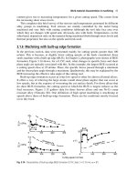
For studs larger than 11/2 in. in diameter, use “Select-A-Torq” hydraulic
wrench (Model 5000 A) supplied by N-S-W Corp. of Houston, Texas, the
“Hydra-Tork” wrench system (Model HT-6) supplied by Torque System,
Inc., the “Hytorc” (Figure 4-10), tensioners by Hydratight-Sweeney
(Figure 4-11), or one of many available Furmanite “Plarad” devices
(Figure 4-12). Torque wrenches can be used on small flanges, with stud
diameters less than 11/2 in. The torque wrenches should be calibrated at
least once per week.
Figure 4-10. “Hytorc” stud tensioner.
180
Machinery Component Maintenance and Repair
Figure 4-11. Tensioners by Hydrotight-Sweeney.
Hot Bolting and Leakage Control
Hot bolting during startup and during process runs has been found to
be an important factor in minimizing flange leakage. During heat-up and
because of temperature changes, the bolts and gaskets deform permanently. This causes a loss of bolt stress after the temperature changes have
smoothed out. Hot bolting helps correct this.
Process Machinery Piping
181
Figure 4-12. Furmanite “Plarad” hydraulic tensioning devices in action.
Hot Bolting Procedure
The objective of hot bolting is to restore the original bolt stress which
has dropped due to yielding and/or creep of the flange joint components.
If possible, this should be done with a bolt tensioning device. Hot bolting
should start at the point of leakage and proceed in a crisscross pattern as
described previously. Seized bolts sometimes present a problem when hot
bolting. In such cases, it is necessary to use a wrench on both nuts.
Using Bolt Tensioners
There exists considerable experience with the use of various bolt tensioners for hot bolting. These procedures typically involve first running a
die over the stud projections to facilitate subsequent installation of the tensioner heads. Mechanics are instructed to leave the heads in place for the
minimum time necessary so as to prevent leakage of hydraulic fluid at the
seals. Past procedures called for immersion of heads in water between
applications; however, this is no longer necessary.
182
Machinery Component Maintenance and Repair
Using Hammer and Wrench or Torque Wrench
If leaks occur, it may be necessary to employ a 7 lb or heavier hammer
to stop the leak. Tightening should first be done where the leakage has
originated and the crisscross pattern should be used from there. Joints with
spiral-wound gaskets can be tightened only to the limit of the steel centering ring thickness. Further tightening is fruitless if a spiral-wound
gasket has already been tightened to this point.
If Hot Bolting Does Not Stop Leak
If leakage cannot be stopped by tightening, the line must be isolated
and the joint broken to determine the cause:
•
•
•
•
•
•
•
•
Examine flange facings for damage, distortion (warping), or foreign
matter
Check flange alignment, cut and realign piping if necessary
Check gasket for proper material, dimensions, and type. Use a new
gasket for reassembly of the joint.
Check gasket deformation to determine if it was centered. This is best
done by noting the position of the gasket before it is withdrawn and
examining it immediately after withdrawal.
Reassemble the joint
If leakage persists, piping support and flexibility must be examined.
It may be necessary to revise the support system or install spring
hangers to lower bending moments.
If leakage occurs during rainstorms, it will be necessary to install
sheet metal rain shields, which may cover the top 180° of the flange,
to prevent such leakage. These should be located about four inches
away from the flange surface and should have sufficient width to
cover the bolts plus two inches on each side.
If leakage occurs during sudden changes in process temperatures,
examine the process sequence to determine if steps can be taken to
minimize rapid heat-up or cooling of lines. It may only be necessary
to open a valve more slowly.
Recommendations for the Installation, Fabrication, Testing,
and Cleaning of Air, Gas or Steam Piping*
The importance of starting any compressor with clean piping, particularly on the intake to any cylinder, cannot be over-emphasized. This is particularly important with multi-stage high-pressure compressors where
* Refer to appendices at the end of this chapter for typical checklists.
Process Machinery Piping
183
special metallic packing is required and parts are much more expensive
than in a low-pressure compressor. Any dirt, rust, welding beads or scale
carried into the compressor will cause scored packing rings, piston rods,
cylinder bores, and pitted, Leaky valves.
It is important that the piping be fabricated with sufficient flange joints
so that it can be dismantled easily for cleaning and testing. It is far better to
clean and test piping in sections before actual erection than after it is in
place.
If it is necessary to conduct the final test when the piping is in position,
care should be taken to provide vents at the high spots so that air or gas
will not be trapped in the piping. Make provision for complete drainage after
the test is completed. These connections should be planned in advance.
When piping is cleaned in sections before erection, it is possible to do
a thorough job of eliminating all acid. This is difficult to do with piping
erected and in position, because carry-over of acid into the cylinders is
almost certain to occur when the machine is started. This can cause extensive damage.
The use of chill-rings for butt welds in piping is recommended. This
prevents welding beads from getting into the pipe to carry through, not
only on the original starting, but later on during operation.
After hydrostatic tests have been made and the pipe sections have been
cleaned as thoroughly as possible on the inside, the piping should be
pickled by this procedure:
1. Pickle for 14 hours with hydrochloric acid. Circulate the acid continuously by means of a small pump. Use a five to 12 percent solution of hydrochloric acid, depending upon the condition of the pipe.
2. Neutralize the caustic.
3. Blow hot air through for several hours.
4. Fill with mineral seal oil and drain.
5. Blow out with hot air.
6. Pipe is now ready to use. If the pipe section is not to be assembled
immediately, seal the ends tightly until ready for use. Then, before
installation, pull through a swab saturated with carbon tetrachloride.
Even though this procedure has been carefully followed; on reciprocating compressor piping, a temporary filter (such as Type PT American
Filter, Type PS Air-Maze, or equal) should be installed in the suction line
to the suction bottle to remove particles 230 microns* (0.009 in. diameter) or larger. Provision must be made in the piping to check the pressure
drop across the filter and to remove the filter cell for cleaning. Filter cell
should be removed and left out only when the inlet line is free of welding
beads, pipe scale, and other extraneous matter.
* 140 microns (0.0055 in. diameter) for nonlubricated cylinders.
184
Machinery Component Maintenance and Repair
On large piping (where a man can work inside), the pickling procedure can be omitted if the piping is cleaned mechanically with a wire
brush, vacuumed and then thoroughly inspected for cleanliness. Time and
trouble taken in the beginning to ensure that the piping is clean will shorten
the break-in period, and may save a number of expensive shutdowns.
Pickling Procedure for Reciprocating Compressor
Suction Piping: Method I
General Recommendations
1. The job should be executed by experienced people.
2. Operators must wear adequate safety equipment (gloves and
glasses).
3. Accomplish entire pickling operation in as short a time as possible.
Preliminary Work
1. Install an acid-resistant pump connected to a circulating tank.
2. Provide 11/2 in. (or greater) acid resistant hoses for the connections
(prepare suitable assembly sketch).
3. For ensuring the filling of the system, flow must go upward and vents
must be installed.
4. Provide method for heating the solutions (e.g., a steam coil).
Pretreatment
Pretreatment is required only when traces of grease are present.
1. Fill the system with water at 90°C (194°F).
2. Add 2 percent sodium hydroxide and 0.5 percent sodium metasilicate (or sodium orthosilicate if cheaper). If these compounds are not
available and only a small amount of grease is present 2 percent of
NaOH and 3 percent of Na2CO3 may be used.
3. Circulate for 20–30 minutes at 90°C (194°F).
4. Dump the solution and wash with water until pH = 7.
Acid Treatment
1. Fill the system with water at 50°C (122°F).
2. Add 4 percent of Polinon 6A® and circulate to ensure its complete
distribution.
Process Machinery Piping
185
3. Add hydrochloric acid to reach the concentration of 7 percent.
4. Circulate intermittently for about 45 minutes or more until the pickling has been accomplished.
Notes:
1. In order to avoid corrosion:
(a) Keep the flow rate lower than 1 m/sec.
(b) Take samples of the solution and check for the Fe+++ content: if
[Fe+++] > 0.4 percent dump solution.
2. In order to determine when the system has been adequately pickled,
put a piece of oxidized steel in the circulation tank and inspect it
frequently.
Neutralization
1. Add sodium hydroxide for neutralizing the acid, and water to avoid
a temperature rise.
2. Circulate for 15–30 minutes.
3. Dump the solution and wash with water until pH = 7.
Note:
The concentration must be calculated on the overall volume of the
solution.
Passivation
1. Fill the system with water at 40°C (104°F).
2. Add 0.5 percent of citric acid and circulate to ensure complete
mixing.
3. Check the pH of the solution: if pH < 3.5, slowly add ammonia to
raise pH to 3.5.
4. Circulate for 15–20 minutes.
5. Slowly add ammonia to raise pH to 6 in 10 minutes.
6. Add 0.5 percent sodium nitrite (or ammonium persulfate).
7. Circulate for 10 minutes.
8. Add ammonia to raise pH to 9.
9. Circulate for 45 minutes.
186
Machinery Component Maintenance and Repair
10. Stop the pump and hold the solution in the system for at least three
hours.
11. Dump the solution.
Cleaning of Large Compressor Piping: Method II
Cleaning of the piping may be done by commercial companies with
mobile cleaning equipment or by the following recommended cleaning
procedure. After hydrostatic tests have been made and the pipe sections
have been cleaned as thoroughly as possible on the inside, the piping
should be pickled by the following (or equivalent) procedure:
1. Remove all grease, dirt, oil, or paint by immersing in a hot, caustic bath. The bath may be a solution of eight ounces of sodium
hydroxide to one gallon of water with the solution temperature
180°–200°F. The time of immersion is at least thirty minutes,
depending on the condition of the material.
2. Remove pipe from caustic and immediately rinse with cold water.
3. Place pipe in an acid pickling bath. Use a 5 to 12 percent solution
of hydrochloric (muriatic) acid, depending upon the condition of the
pipe. Rodine inhibitor should be added to the solution to prevent
the piping from rusting quickly after removal from the acid bath. The
temperature of the bath should be 140°–165°F. The time required
in the acid bath to remove scale and rust will vary, depending on the
solution strength and condition of piping; however, six hours should
be a minimum. The normal time required is about 12 to 14 hours.
4. Remove pipe from acid bath and immediately wash with cold water
to remove all traces of acid.
5. Without allowing piping to dry, immerse in a hot neutral solution.
A one to two ounce soda ash per gallon of water solution may be
used to maintain a pH of 9 or above. The temperature of the solution should be 160°–170°F. Litmus paper may be used to check the
wet piping surface to determine that an acidic condition does not
exist. If acidic, then repeat neutral solution treatment.
6. Rinse pipe with cold water, drain thoroughly and blow out with hot
air until dry.
7. Immediate steps must be taken to prevent rusting, even if piping
will be placed in service shortly. Generally, a dip or spray coating
of light water displacement mineral oil will suffice; however, if
piping is to be placed in outdoor storage for more than several
weeks, a hard-coating water displacement type rust preventative
should be applied.
Process Machinery Piping
187
8. Unless piping is going to be placed in service immediately, suitable gasketed closures must be placed on the ends of the piping
and all openings to prevent entrance of moisture or dirt. Use of
steel plate discs and thick gaskets is recommended for all flanges.
Before applying closures, the flange surfaces should be coated with
grease.
9. Before installation, check that no dirt or foreign matter has entered
piping and that rusting has not occurred. If in good condition, then
pull through a swab saturated with carbon tetrachloride.
10. For nonlubricated (NL) units where oil coating inside piping is not
permissible (due to process contamination), even for the starting
period, consideration should be given to one of the following
alternatives:
(a) Use of nonferrous piping materials, such as aluminum.
(b) Application of a plastic composition or other suitable coating
after pickling to prevent rusting.
(c) After rinsing with water in step six, immerse piping in a hot
phosphoric bath. The suggested concentration is three to six
ounces of iron phosphate per gallon of water, heated to
160°–170°F, with pH range of 4.2 to 4.8. The immersion time
is three to five minutes or longer, depending on density of
coating required. Remove and dry thoroughly, blowing out with
hot air.
CAUTION: Hydrochloric acid in contact with the skin can
cause burns. If contacted, acid should be washed
off immediately with water. Also, if indoors, adequate ventilation, including a vent hood, should
be used. When mixing the solution, always add
the acid to the water, never the water to the acid.
On large piping (where a man can work inside), the pickling procedure
can be omitted if the piping is cleaned mechanically with a wire brush,
vacuumed and then thoroughly inspected for cleanliness. Time and trouble
taken in the beginning to insure that the piping is clean will shorten the
break-in period, and may save a number of expensive shut downs.
Temporary Line Filters
When first starting, it is advisable to use a temporary line filter in the
intake line near the compressor to catch any dirt, chips, or other foreign
188
Machinery Component Maintenance and Repair
material that may have been left in the pipe. But clean the pipe first. Do
not depend on a temporary line filter. If the gas or air being compressed
may, at times, contain dust, sand, or other abrasive particles, a gas scrubber or air cleaner must be installed permanently and serviced regularly.
Even though the previous cleaning procedure has been carefully followed on the compressor piping, a temporary filter (such as Type PT
American Filter or equal) should be installed in the suction line to the
suction bottle to remove particles 230 microns (0.009 in.) in diameter or
larger. If the compressor is an “NL” (nonlubricated) design, the filter
should be designed to remove particles 140 microns (0.0055 in.) in diameter or larger. Provision must be made in the piping to check the pressure drop across the filter and to remove the filter cell for cleaning. If the
pressure drop across the filter exceeds 5 percent of the upstream line pressure, remove the filter, clean thoroughly and reinstall. The filter cell should
be removed and left out only when the inlet line is free of welding beads,
pipe scale, and other extraneous matter.
Appendix 4-A
Detailed Checklist for Rotating
Equipment: Machinery Piping*
189