Machinery Components Maintenance And Repair Episode 1 Part 9 pps
Bạn đang xem bản rút gọn của tài liệu. Xem và tải ngay bản đầy đủ của tài liệu tại đây (445.67 KB, 25 trang )
190
Machinery Component Maintenance and Repair
Appendix 4-B
Specifications for Cleaning
Mechanical Seal Pots and
Piping for Centrifugal Pumps
191
192
Machinery Component Maintenance and Repair
Process Machinery Piping
193
Appendix 4-C
Detailed Checklist for Rotating
Equipment: Pump Piping
194
Process Machinery Piping
195
This page intentionally left blank
Part II
Alignment and
Balancing
This page intentionally left blank
Chapter 5
Machinery Alignment*
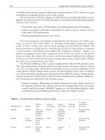
For most rotating machines used in the process industries, the trend is
toward higher speeds, higher horsepowers per machine, and less sparing.
The first of these factors increases the need for precise balancing and
alignment. This is necessary to minimize vibration and premature wear of
bearings, couplings, and shaft seals. The latter two factors increase the
economic importance of high machine reliability, which is directly dependent on minimizing premature wear and breakdown of key components.
Balancing, deservedly, has long received attention from machinery manufacturers and users as a way to minimize vibration and wear. Many shop
and field balancing machines, instruments, and methods have become
available over the years. Alignment, which is equally important, has
received proportionately less notice than its importance justifies.
Any kind of alignment, even straightedge alignment, is better than no
alignment at all. Precise, two-indicator alignment is better than rough
alignment, particularly for machines 3,600 rpm and higher. It can give
greatly improved bearing and seal life, lower vibration, and better overall
reliability. It does take longer, however, especially the first time it is done
to a particular machine, or when done by inexperienced personnel. The
process operators and mechanical supervisors must be made aware of this
time requirement. If they insist on having the job done in a hurry, they
should do so with full knowledge of the likelihood of poor alignment and
reduced machine reliability. Figure 5-1 shows a serious machinery failure
* Main source: Malcolm G. Murray, Jr., Alignment Manual for Horizontal, FlexiblyCoupled Rotating Machines available from publisher, Murray and Garig Tool Works, 220
East, Texas Avenue, Baytown, Texas 77520; Tel. (281) 427-5923. Adapted by permission.
Certain portions of this chapter, e.g., laser-optic alignment and some of the alignment tolerance criteria, are from other sources.
199
200
Machinery Component Maintenance and Repair
Figure 5-1. Machinery damage caused by bearing seizure. Bearing seizure was the result
of gear coupling damage, and gear coupling damage was caused by excessive misalignment, caused by piping forces.
which started with piping-induced misalignment, progressed to coupling
distress, bearing failure, and finally, total wreck.
Prealignment Requirements
The most important requirement is to have someone who knows what
he is doing, and cares enough to do it right. Continuity is another important factor. Even with good people, frequent movement from location to
location can cause neglect of things such as tooling completeness and prealignment requirements.
The saying that “you can’t make a silk purse out of a sow’s ear” also
applies to machinery alignment. Before undertaking an alignment job, it
is prudent to check for other deficiencies which would largely nullify the
benefits or prevent the attainment and retention of good alignment. Here
is a list of such items and questions to ask oneself:
Machinery Alignment
Foundation
Grout
Baseplate
Piping
201
Adequate size and good condition? A rule of thumb calls
for concrete weight equal to three times machine weight for
rotating machines, and five times for reciprocating machines.
Suitable material, good condition, with no voids remaining
beneath baseplate? Tapping with a small hammer can detect
hollow spots, which can then be filled by epoxy injection
or other means. This is a lot of trouble, though, and often
is not necessary if the lack of grout is not causing vibration or alignment drift.
Designed for adequate rigidity? Machine mounting pads
level, flat, parallel, coplanar, clean? Check with straightedge and feeler gauge. Do this upon receipt of new pumps,
to make shop correction possible—and maybe collect the
cost from the pump manufacturer. Shims clean, of adequate
thickness, and of corrosion- and crush-resistant material?
If commercial pre-cut shims are used, check for actual
versus marked thicknesses to avoid a soft foot condition.
Machine hold-down bolts of adequate size, with clearance
to permit alignment corrective movement? Pad height
leaving at least 2 in. jacking clearance beneath center at
each end of machine element to be adjusted for alignment?
If jackscrews are required, are they mounted with legs sufficiently rigid to avoid deflection? Are they made of type
316 stainless steel, or other suitable material, to resist field
corrosion? Water or oil cooled or heated pedestals are
usually unnecessary, but can in some cases be used for
onstream alignment thermal compensation.
Is connecting piping well fitted and supported, and sufficiently flexible, so that no more than 0.003 in. vertical and
horizontal (measured separately—not total) movement
occurs at the flexible coupling when the last pipe flanges
are tightened? Selective flange bolt tightening may be
required, while watching indicators at the coupling. If pipe
flange angular misalignment exists, a “dutchman” or
tapered filler piece may be necessary. To determine filler
piece dimensions, measure flange gap around circumference, then calculate as follows:
1
8
È Gasket O.D. ˘
=
in. + (Max. Gap - Min. Gap) Í
˚
Ỵ Flange O.D. ˙
Maximum Thickness of
Tapered Filler Piece
202
Machinery Component Maintenance and Repair
/8 in. = Dutchman Minimum Thickness (180° from
Maximum Thickness). Dutchman OD and ID same as
gasket OD and ID.
Spiral wound gaskets may be helpful, in addition to or
instead of a tapered filler piece. Excessive parallel offset at
the machine flange connection cannot be cured with a filler
piece. It may be possible to absorb it by offsetting several
successive joints slightly, taking advantage of clearance
between flange bolts and their holes. If excessive offset
remains, the piping should be bent to achieve better fit. For
the “stationary” machine element, the piping may be connected either before or after the alignment is done—provided the foregoing precautions are taken, and final
alignment remains within acceptable tolerances. In some
cases, pipe expansion or movement may cause machine
movement leading to misalignment and increased vibration. Better pipe supports or stabilizers may be needed in
such situations. At times it may be necessary to adjust these
components with the machine running, thus aligning the
machine to get minimum vibration. Sometimes, changing
to a more tolerant type of coupling, such as elastomeric,
may help.
Coupling
Some authorities recommend installation on typical pumps
Installation and drivers with an interference fit, up to 0.0005 in. per in.
of shaft diameter. In our experience, this can give problems
in subsequent removal or axial adjustment. If an interference fit is to be used, we prefer a light one—say 0.0003 in.
to 0.0005 in. overall, regardless of diameter. For the majority of machines operating at 3,600 rpm and below, you can
install couplings with 0.0005 in. overall diametral clearance, using a setscrew over the keyway. For hydraulic dilation couplings and other nonpump or special categories, see
manufacturers’ recommendations or appropriate section of
this text. Many times, high-performance couplings require
interference fits as high as 0.0025 in. per in. of shaft
diameter.
Coupling cleanliness, and for some types, lubrication,
are important and should be considered. Sending a repaired
machine to the field with its lubricated coupling-half unprotected, invites lubricant contamination, rusting, dirt accumulation, and premature failure. Lubricant should be
chosen from among those recommended by the coupling
manufacturer or a reputable oil company. Continuous
1
Machinery Alignment
203
running beyond two years is inadvisable without inspecting a grease lubricated coupling, since the centrifuging
effects are likely to cause caking and loss of lubricity.
Certain lubricants, e.g., Amoco and Koppers coupling
greases, are reported to eliminate this problem, but visual
external inspection is still advisable to detect leakage. Continuous lube couplings are subject to similar problems,
although such remedies as anti-sludge holes can be used to
allow longer runs at higher speeds. By far the best remedy
is clean oil, because even small amounts of water will
promote sludge formation. Spacer length can be important,
since parallel misalignment accommodation is directly proportional to such length.
Alignment Tolerances
Before doing an alignment job, we must have tolerances to work toward.
Otherwise, we will not know when to stop. One type of “tolerance” makes
time the determining factor, especially on a machine that is critical to plant
operation, perhaps the only one of its kind. The operations superintendent
may only be interested in getting the machine back on the line, fast. If his
influence is sufficient, the job may be hurried and done to rather loose
alignment tolerances. This can be unfortunate, since it may cause excessive vibration, premature wear, and early failure. This gets us back to the
need for having the tools and knowledge for doing a good alignment job
efficiently. So much for the propaganda—now for the tolerances.
Tolerances must be established before alignment, in order to know when
to stop. Various tolerance bases exist. One authority recommends 1/2-mil
maximum centerline offset per in. of coupling length, for hot running misalignment. A number of manufacturers have graphs which recommend tolerances based on coupling span and speed. A common tolerance in terms
of face-and-rim measurements is 0.003-in, allowable face gap difference
and centerline offset. This ignores the resulting accuracy variation due to
face diameter and spacer length differences, but works adequately for
many machines.
Be cautious in using alignment tolerances given by coupling manufacturers. These are sometimes rather liberal and, while perhaps true for the
coupling itself, may be excessive for the coupled machinery.
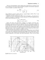
A better guideline is illustrated in Figure 5-2, which shows an upper,
absolute misalignment limit, and a lower, “don’t exceed for good longterm operation limit.” The real criterion is the running vibration. If
204
Machinery Component Maintenance and Repair
Figure 5-2. Misalignment tolerances.
excessive, particularly at twice running frequency and axially, further
alignment improvement is probably required. Analysis of failed components such as bearings, couplings, and seals can also indicate the need for
improved alignment.
Figure 5-2 can be applied to determine allowable misalignment for
machinery equipped with nonlubricated metal disc and diaphragm couplings, up to perhaps 10,000 rpm. If the machinery is furnished with geartype couplings, Figure 5-2 should be used up to 3,600 rpm only. At speeds
higher than 3,600 rpm, gear couplings will tolerate with impunity only
those shaft misalignments which limit the sliding velocity of engaging
gear teeth to less than perhaps 120 in. per minute. For gear couplings, this
velocity can be approximated by V = (pDN) tan a, where
D = gear pitch diameter, in.
N = revolutions per minute
Machinery Alignment
205
2 tan a = total indicator reading obtained at hub outside diameter,
divided by distance between indicator planes on driver and
driven equipment couplings.
Say, for example, we were dealing with a 3,560 rpm pump coupled to a
motor driven via a 6-in. pitch diameter gear coupling. We observe a total
indicator reading of 26 mils in the vertical plane and a total indicator
reading of 12 mils in the horizontal plane. The distance between the flexing
member of the coupling, i.e., flexing member on driver and flexing member
1
on driven machine, is 10 in. The total net indicator reading is [(26)2 + (12)2] /2
= 28.6 mils. Tan a (1/2)(28.6)/10) = 1.43 mils/in., or 0.00143 in./in. The
sliding velocity is therefore [(p)(6)(3560)(0.00143)] = 96 in. per minute.
Since this is below the maximum allowable sliding velocity of 120 in. per
minute, the installation would be within allowable misalignment.
Choosing an Alignment Measurement Setup
Having taken care of the preliminaries, we are now ready to choose an
alignment setup, or arrangement of measuring instruments. Many such
setups are possible, generally falling into three broad categories: face-andrim, reverse-indicator, and face-face-distance. The following sketches
show several of the more common setups, numbered arbitrarily for ease
of future reference. Note that if measurements are taken with calipers or
ID micrometers, it may be necessary to reverse the sign from that which
would apply if dial indicators are used.
Figures 5-3 through 5-8 show several common arrangements of indicators, jigs, etc. Other arrangements are also possible. For example,
Figures 5-3 and 5-4 can be done with jigs, either with or without breaking the coupling. They can also sometimes be done when no spacer is
present, by using right-angle indicator extension tips. Figures 5-6 and 57 can be set up with both extension arms and indicators on the same side,
rather than 180° opposite as shown. In such cases, however, a sign reversal will occur in the calculations. Also, we can indicate on back of face,
as for connected metal disc couplings. Again, a sign reversal will occur.
In choosing the setup to use, personal preference and custom will naturally influence the decision, but here are some basic guidelines to follow.
Reverse-Indicator Method
This is the setup we prefer for most alignment work. As illustrated in
Figure 5-9, it has several advantages:
206
Machinery Component Maintenance and Repair
Figure 5-3. Two-indicator face-and-rim alignment method.
Figure 5-4. Three-indicator face-and-rim alignment method.
Machinery Alignment
Figure 5-5. Close-coupled face-and-rim alignment method.
Figure 5-6. Reverse-indicator alignment using clamp-on jigs.
207
208
Machinery Component Maintenance and Repair
Figure 5-7. Reverse-indicator alignment using face-mounted brackets or any other
brackets which hold the indicators as shown.
Figure 5-8. Two-indicator face-face-distance alignment method.
1. Accuracy is not affected by axial movement of shafts in sleeve
bearings.
2. Both shafts turn together, either coupled or with match marks, so
coupling eccentricity and surface irregularities do not reduce accuracy of alignment readings.
3. Face alignment, if desired, can be derived quite easily without direct
measurement.
4. Rim measurements are easy to calibrate for bracket sag. Face sag,
by contrast, is considerably more complex to measure.
5. Geometric accuracy is usually better with reverse-indicator method
in process plants, where most couplings have spacers.
6. With suitable clamp-on jigs, the reverse-indicator method can be
used quite easily for measuring without disconnecting the coupling
or removing its spacer. This saves time, and for gear couplings,
reduces the chance for lubricant contamination.
7. For the more complex alignment situations, where thermal growth
and/or multi-element trains are involved, reverse-indicator can be
Machinery Alignment
209
Figure 5-9. Reverse-indicator setup.
used quite readily to draw graphical plots showing alignment conditions and moves. It is also useful for calculating optimum moves
of two or more machine elements, when physical limits do not
allow full correction to be made by moving a single element.
8. When used with jigs and posts, single-axis leveling is sufficient for
ball-bearing machines, and two-axis leveling will suffice for sleevebearing machines.
9. For long spans, adjustable clamp-on jigs are available for reverseindicator application, without requiring coupling spacer removal.
Face-and-rim jigs for long spans, by contrast, are usually nonadjustable custom brackets requiring spacer removal to permit face
mounting.
10. With the reverse-indicator setup, we mount only one indicator per
bracket, thus reducing sag as compared to face-and-rim, which
mounts two indicators per bracket. (Face-and-rim can do it with
one per bracket if we use two brackets, or if we remount indicators
and rotate a second time, but this is more trouble.)
There are some limitations of the reverse-indicator method. It should
not be used on close-coupled installations, unless jigs can be attached
210
Machinery Component Maintenance and Repair
behind the couplings to extend the span to 3 in. or more. Failure to observe
this limitation will usually result in calculated moves which overcorrect
for the misalignment.
Both coupled shafts must be rotatable, preferably by hand, and preferably while coupled together. If only one shaft can be rotated, or if neither
can be rotated, the reverse-indicator method cannot be used.
If the coupling diameter exceeds available axial measurement span,
geometric accuracy will be poorer with reverse-indicator than with faceand-rim.
If required span exceeds jig span capability, either get a bigger jig or
change to a different measurement setup such as face-face-distance.
Cooling tower drives would be an example of this.
Face-and-Rim Method
This is the “traditional” setup which is probably the most popular,
although it is losing favor as more people learn about reverse-indicator.
Advantages of face-and-rim:
1. It can be used on large, heavy machines whose shafts cannot be
turned.
2. It has better geometric accuracy than reverse-indicator, for large
diameter couplings with short spans.
3. It is easier to apply on short-span and small machines than is reverseindicator, and will often give better accuracy.
Limitations of face-and-rim:
1. If used on a machine in which one or both shafts cannot be
turned, some runout error may occur, due to shaft or coupling
eccentricity.
2. If used on a sleeve bearing machine, axial float error may occur. One
method of avoiding this is to bump the turned shaft against the axial
stop each time before reading. Another way is to use a second face
indicator 180° around from the first, and take half the algebraic difference of the two face readings after 180° rotation from zero start.
Figure 5-10 illustrates this alignment method. Two 2-in. tubular
graphite jigs are used for light weight and high rigidity.
3. If used with jigs and posts, two or three axis leveling is required, for
ball and sleeve bearing machines respectively. Reverse-indicator
requires leveling in one less axis for each.
4. Face-and-rim has lower geometric accuracy than reverse-indicator,
for spans exceeding coupling or jig diameter.
Machinery Alignment
211
Figure 5-10. Face-and-rim indicator setup using lightweight, high-rigidity tubular graphite
fiber-reinforced epoxy jigs.
5. Face sag is often insignificant, but it can occur on some setups, and
result in errors if not accounted for. Calibration for face sag is considerably more complex than for rim sag.
6. For long spans, face-and-rim jigs are usually custom-built brackets
requiring spacer removal to permit face mounting. Long-span
reverse-indicator jigs, by contrast, are available in adjustable clampon models not requiring spacer removal.
7. Graphing the results of face-and-rim measurements is more complex
than with reverse-indicator measurements.
Face-Face-Distance Method
Advantages of face-face-distance:
1. It is usable on long spans, such as cooling tower drives, without elaborate long-span brackets or consideration of bracket sag.
2. It is the basis for thermal growth measurement in the Indikon proximity probe system, and again is unaffected by long axial spans.
3. It is sometimes a convenient method for use with diaphragm couplings such as Lucas Aerospace (Utica, New York), allowing mounting of indicator holders on spacer tube, with indicator contact points
on diaphragm covers.
212
Machinery Component Maintenance and Repair
Limitations of face-face-distance:
1. It has no advantage over the other methods for anything except long
spans.
2. It cannot be used for installations where no coupling spacer is
present.
3. Its geometric accuracy will normally be lower than either of the other
two methods.
4. It may or may not be affected by axial shaft movement in sleeve bearings, but this can be avoided by the same techniques as for face-andrim.
Laser-Optic Alignment
In the early 1980s, by means of earth-bound laser beams and a reflector mounted on the moon, man has determined the distance between earth
and the moon to within about 6 inches.
Such accuracy is a feature of optical measurement systems, as light
travels through space in straight lines, and a bundled laser ray with particular precision.
Thus, critical machinery alignment, where accuracy of measurement is
of paramount importance, is an ideal application for a laser-optic alignment system.
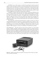
The inherent problems of mechanical procedure and sequence of measuring have been solved by Prüftechnik Dieter Busch, of Ismaning,
Germany, whose OPTALIGN® system (Figure 5-11) comprises a semiconductor laser emitting a beam in the infrared range (wavelength 820
mm), along with a beamfinder incorporating an infrared detector. The laser
beam is refracted through a prism and is caught by a receiver/detector.
These light-weight, nonbulky devices are mounted on the equipment
shafts, and only a cord-connected microcomputer module is external to
the beam emission and receiver/detector devices.
The prism redirects the beam and allows measurement of parallel offset
in one plane and angularity in another, thus simultaneously controlling
both. In one 90° rotation of the shafts all four directional alignment corrections are determined.
With the data automatically obtained from the receiver/detector, the
microcomputer instantaneously yields the horizontal and vertical adjustment results for the alignment of the machine to be moved.
Physical contact between measuring points on both shafts is no longer
required, as this is now bridged by the laser beam, eliminating the possibilities for error arising from gravitational hardware sag as well as from
Machinery Alignment
213
Figure 5-11. Optalign® laser-optic alignment system.
sticky dial indicators, etc. The system’s basic attachment is still carried
out with a standard quick-fit bracketing system, or with any other suitable
attachment hardware.
If the reader owns an OPTALIGN® or the newer “smartALIGN®”
(Figure 5-12) system, he does not have to be concerned with sag. Other
reader must continue the checkout process.
Checking for Bracket Sag
Long spans between coupling halves may cause the dial indicator
fixture to sag measurably because of the weight of the fixture and the dial
214
Machinery Component Maintenance and Repair
Figure 5-12. SmartALIGN® system. (Source: Prüftechnik, A. G., Ismaning, Germany.)
indicators. Although sag may be minimized by proper bracing, sag effects
should still be considered in vertical alignment. To determine sag, install
the dial indicators on the alignment fixture in the same orientation and relative position as in the actual alignment procedure with the fixture resting
on a level surface as shown in Figure 5-13. With a small sling and scale,
lift the indicator end of the fixture so that the fixture is in the horizontal
position. Note the reading on the scale. Assume for example that the scale
reading was 7.5 lbs. Next, mount the alignment fixture on the coupling