(McGraw-Hill) (Instructors Manual) Electric Machinery Fundamentals 4th Edition Episode 2 Part 6 ppt
Bạn đang xem bản rút gọn của tài liệu. Xem và tải ngay bản đầy đủ của tài liệu tại đây (1.1 MB, 20 trang )
295
Appendix C:
Salient Pole Theory of Synchronous Machines
C-1. A 480-V 200-kVA 0.8-PF-lagging 60-Hz four-pole Y-connected synchronous generator has a direct-axis
reactance of 0.25
Ω
, a quadrature-axis reactance of 0.18
Ω
, and an armature resistance of 0.03
Ω
.
Friction, windage, and stray losses may be assumed negligible. The generator’s open-circuit characteristic
is given by Figure P5-1.
(a) How much field current is required to make
V
T
equal to 480 V when the generator is running at no
load?
(b) What is the internal generated voltage of this machine when it is operating at rated conditions? How
does this value of
E
A
compare to that of Problem 5-2b?
(c) What fraction of this generator’s full-load power is due to the reluctance torque of the rotor?
S
OLUTION
(a) If the no-load terminal voltage is 480 V, the required field current can be read directly from the open-
circuit characteristic. It is 4.55 A.
(b) At rated conditions, the line and phase current in this generator is
()
A 6.240
V 4803
kVA 200
3
====
L
LA
V
P
II
at an angle of –36.87°
296
′′ = + +EV I I
AAAqA
RjX
φ
()()()()
A 87.366.240 18.0A 87.366.240 03.00277 °−∠Ω+°−∠Ω+°∠=
′′
j
A
E
V 61.5310 °∠=
′′
A
E
Therefore, the torque angle
δ
is 5.61
°
. The direct-axis current is
()
°−∠+= 90 sin
δδθ
Ad
II
()()
°−∠°= 4.84 48.42sinA 6.240
d
I
A 4.84 5.162 °−∠=
d
I
The quadrature-axis current is
()
δδθ
∠+= cos
Aq
II
()()
°∠°= 61.5 48.42cosA 6.240
q
I
A 61.5 4.177 °∠=
q
I
Therefore, the internal generated voltage of the machine is
qqddAAA
jXjXR IIIVE +++=
φ
()( )()( )()( )
°∠+°−∠+°−∠+°∠= 61.54.17718.04.845.16225.087.366.24003.00277 jj
A
E
V 61.5322 °∠=
A
E
A
E
is approximately the same magnitude here as in Problem 5-2b, but the angle is about 2.2° different.
(c) The power supplied by this machine is given by the equation
P
VE
X
VX X
XX
A
d
dq
dq
=+
−
33
2
2
φφ
δδ sin sin 2
()() ()
()()
°
−
+°5=
1.221 sin
18.025.0
18.025.0
2
2773
.61 sin
25.0
3222773
2
P
kW 139.4kW 8.34kW 6.104
=
+
=
P
The cylindrical rotor term is 104.6 kW, and the reluctance term is 34.8 kW, so the reluctance torque
accounts for about 25% of the power in this generator.
297
C-2. A 14-pole Y-connected three-phase water-turbine-driven generator is rated at 120 MVA, 13.2 kV, 0.8 PF
lagging, and 60 Hz. Its direct-axis reactance is 0.62
Ω
and its quadrature- axis reactance is 0.40
Ω
. All
rotational losses may be neglected.
(a) What internal generated voltage would be required for this generator to operate at the rated conditions?
(b) What is the voltage regulation of this generator at the rated conditions?
(c) Sketch the power-versus-torque-angle curve for this generator. At what angle δ is the power of the
generator maximum?
(d) How does the maximum power out of this generator compare to the maximum power available if it
were of cylindrical rotor construction?
S
OLUTION
(a) At rated conditions, the line and phase current in this generator is
()
A 5249
kV 2.133
MVA120
3
====
L
LA
V
P
II
at an angle of –36.87
°
′′
=+ +
EV I I
AAAqA
RjX
φ
()( )
A 87.365249 40.0007621 °−∠Ω++°∠=
′′
j
A
E
V 7.109038 °∠=
′′
A
E
Therefore, the torque angle
δ
is 10.7
°
. The direct-axis current is
()
°−∠+= 90 sin
δδθ
Ad
II
()()
°−∠°= 3.79 57.47sinA 2495
d
I
A 3.79 3874 °−∠=
d
I
The quadrature-axis current is
()
δδθ
∠+= cos
Aq
II
()()
°∠°= 7.10 57.47cosA 2495
q
I
A 7.10 3541 °∠=
q
I
Therefore, the internal generated voltage of the machine is
qqddAAA
jXjXR IIIVE +++=
φ
()( )()( )
°∠+°−∠++°∠= 7.103541 40.03.793874 62.0007621 jj
A
E
V 7.109890 °∠=
A
E
(b) The voltage regulation of this generator is
%8.29%100
7621
76219890
%100
fl
flnl
=×
−
=×
−
V
VV
(c) The power supplied by this machine is given by the equation
P
VE
X
VX X
XX
A
d
dq
dq
=+
−
33
2
2
φφ
δδ sin sin 2
298
()() ()
()()
δδ
2 sin
40.0 62.0
40.062.0
2
76213
sin
62.0
989076213
2
−
+=P
MW2 sin 3.77 sin 7.364
δ
δ
+=P
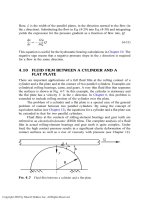
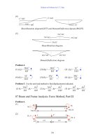
A plot of power supplied as a function of torque angle is shown below:
The peak power occurs at an angle of 70.6°, and the maximum power that the generator can supply is
392.4 MW.
(d) If this generator were non-salient,
MAX
P would occur when
δ
= 90
°
, and
MAX
P would be 364.7 MW.
Therefore, the salient-pole generator has a higher maximum power than an equivalent non-salint pole
generator.
C-3. Suppose that a salient-pole machine is to be used as a motor.
(a) Sketch the phasor diagram of a salient-pole synchronous machine used as a motor.
(b) Write the equations describing the voltages and currents in this motor.
(c) Prove that the torque angle
δ
between
E
A
and V
φ
on this motor is given by
δ
θθ
θθ
φ
=
+
tan
cos - sin
sin + cos
-1
IX IR
VIX IR
Aq AA
Aq AA
S
OLUTION
299
300
C-4. If the machine in Problem C-1 is running as a motor at the rated conditions, what is the maximum torque
that can be drawn from its shaft without it slipping poles when the field current is zero?
S
OLUTION
When the field current is zero,
A
E
= 0, so
−
=
δ
φ
2 sin
2
3
2
qd
qd
XX
XXV
P
()
()()
kW 2 sin2 sin
18.025.0
18.025.0
2
2773
2
δδ
179=
−
=P
At
°= 45
δ
, 179 kW can be drawn from the motor.
301
Appendix D:
Errata for Electric Machinery Fundamentals 4/e
(Current at 10 January 2004)
Please note that some or all of the following errata may be corrected in future reprints of the
book, so they may not appear in your copy of the text. PDF pages with these corrections are attached to
this appendix; please provide them to your students.
1. Page 56, Problem 1-6, there are 400 turns of wire on the coil, as shown on Figure P1-3. The body of
the problem incorrectly states that there are 300 turns.
2. Page 56, Problem 1-7, there are 400 turns of wire on the left-hand coil, and 300 turns on the right-
hand coil, as shown on Figure P1-4. The body of the problem is incorrect.
3. Page 62, Problem 1-19, should state: “Figure P1-14 shows a simple single-phase ac power system
with three loads. The voltage source is
120 0 V=∠°V , and the three loads are …”
4. Page 64, Problem 1-22, should state: “If the bar runs off into a region where the flux density falls to
0.30 T… ”. Also, the load should be 10 N, not 20.
5. Page 147, Problem 2-10, should state that the transformer bank is
Y-
∆
, not
∆
-Y.
6. Page 226, Problem 3-10, the holding current
H
I should be 8 mA.
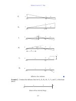
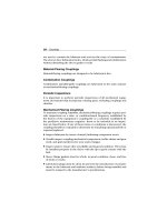
7. Page 342, Figure p5-2, the generator for Problems 5-11 through 5-21, the OCC and SCC curves are
in error. The correct curves are given below. Note that the voltage scale and current scales were
both off by a factor of 2.
302
8. Page 344, Problem 5-28, the voltage of the infinite bus is 12.2 kV.
9. Page 377, Problem 6-11, the armature resistance is 0.08 Ω, and the synchronous reactance is 1.0 Ω.
10. Page 470, Problem 7-20 (a), the holding the infinite bus is 460-V.
303
11. Page 623, Figure P9-2 and Figure P9-3, 0.40
A
R =Ω and 100
F
R =Ω. Values are stated correctly
in the text but shown incorrectly on the figure.
12. Page 624, Figure P9-4, 0.44
AS
RR+= Ω and 100
F
R =Ω. Values are stated correctly in the text
but shown incorrectly on the figure.
13. Page 627, Problem 9-21,
adj
R is currently set to 90
Ω
. Also, the magnetization curve is taken at 1800
r/min.
14. Page 627, Problem 9-22,
A
R
is 0.18 Ω.
15. Page 630, Figure P9-10, 0.21
AS
RR+= Ω
SE
N is 20 turns. Values are stated correctly in the text
but shown incorrectly on the figure.
16. Page 680, Problem 10-6, refers to Problem 10-5 instead of Problem 10-4.
56 ELECTRIC MACHINERY FUNDAMENTALS
1–4. A motor is supplying 60 N • m of torque to its load. If the motor’s shaft is turning at
1800 r/min, what is the mechanical power supplied to the load in watts? In horse-
power?
1–5. A ferromagnetic core is shown in Figure P1–2. The depth of the core is 5 cm. The
other dimensions of the core are as shown in the figure. Find the value of the current
that will produce a flux of 0.005 Wb. With this current, what is the flux density at
the top of the core? What is the flux density at the right side of the core? Assume
that the relative permeability of the core is 1000.
1–6. A ferromagnetic core with a relative permeability of 1500 is shown in Figure P1–3.
The dimensions are as shown in the diagram, and the depth of the core is 7 cm. The
air gaps on the left and right sides of the core are 0.070 and 0.050 cm, respectively.
Because of fringing effects, the effective area of the air gaps is 5 percent larger than
their physical size. If there are 400 turns in the coil wrapped around the center leg
of the core and if the current in the coil is 1.0 A, what is the flux in each of the left,
center, and right legs of the core? What is the flux density in each air gap?
1–7. A two-legged core is shown in Figure P1–4. The winding on the left leg of the core
(N
1
) has 400 turns, and the winding on the right (N
2
) has 300 turns. The coils are
wound in the directions shown in the figure. If the dimensions are as shown, then
what flux would be produced by currents i
1
ϭ 0.5 A and i
2
ϭ 0.75 A? Assume
r
ϭ
1000 and constant.
1–8. A core with three legs is shown in Figure P1–5. Its depth is 5 cm, and there are 200
turns on the leftmost leg. The relative permeability of the core can be assumed to be
1500 and constant. What flux exists in each of the three legs of the core? What is the
flux density in each of the legs? Assume a 4 percent increase in the effective area of
the air gap due to fringing effects.
15 cm
5 cm
20 cm10 cm
i
400 turns
Core depth ϭ 5 cm
φ
φ
15 cm
15 cm
+
–
FIGURE P1–2
The core of Problems 1–5 and 1–16.
cha65239_ch01.qxd 10/16/2003 9:54 AM Page 56
62 ELECTRIC MACHINERY FUNDAMENTALS
(d) Calculate the reactive power consumed or supplied by this load. Does the load
consume reactive power from the source or supply it to the source?
1–19. Figure P1–14 shows a simple single-phase ac power system with three loads. The
voltage source is V = 120∠0° V, and the impedances of the three loads are
Z
1
ϭ 5Є30° ⍀ Z
2
ϭ 5Є45° ⍀ Z
3
ϭ 5ЄϪ90° ⍀
Answer the following questions about this power system.
(a) Assume that the switch shown in the figure is open, and calculate the current I,
the power factor, and the real, reactive, and apparent power being supplied by
the load.
N turns
l
c
= 48 cm
l
r
= 4 cm
4 cm
Depth = 4 cm
4 cm
4 cm
l
g
= 0.05 cm
i
N = ?
FIGURE P1–13
The core of Problem 1–17.
t (ms)
12345678
0
φ
(Wb)
0.010
0.005
–0.005
– 0.010
FIGURE P1–12
Plot of flux
as a function of time for Problem 1–16.
cha65239_ch01.qxd 10/23/2003 9:22 AM Page 62
64 ELECTRIC MACHINERY FUNDAMENTALS
(a) If this bar has a load of 10 N attached to it opposite to the direction of motion,
what is the steady-state speed of the bar?
(b) If the bar runs off into a region where the flux density falls to 0.30 T, what hap-
pens to the bar? What is its final steady-state speed?
(c) Suppose V
B
is now decreased to 80 V with everything else remaining as in
part b. What is the new steady-state speed of the bar?
(d) From the results for parts b and c, what are two methods of controlling the
speed of a linear machine (or a real dc motor)?
REFERENCES
1. Alexander, Charles K., and Matthew N. O. Sadiku: Fundamentals of Electric Circuits, McGraw-
Hill, 2000.
2. Beer, F., and E. Johnston, Jr.: Vector Mechanics for Engineers: Dynamics, 6th ed., McGraw-Hill,
New York, 1997.
3. Hayt, William H.: Engineering Electromagnetics, 5th ed., McGraw-Hill, New York, 1989.
4. Mulligan, J. F.: Introductory College Physics, 2nd ed., McGraw-Hill, New York, 1991.
5. Sears, Francis W., Mark W. Zemansky, and Hugh D. Young: University Physics, Addison-Wesley,
Reading, Mass., 1982.
cha65239_ch01.qxd 10/16/2003 9:54 AM Page 64
TRANSFORMERS 147
2–8. A 200-MVA, 15/200-kV single-phase power transformer has a per-unit resistance of
1.2 percent and a per-unit reactance of 5 percent (data taken from the transformer’s
nameplate). The magnetizing impedance is j80 per unit.
(a) Find the equivalent circuit referred to the low-voltage side of this transformer.
(b) Calculate the voltage regulation of this transformer for a full-load current at
power factor of 0.8 lagging.
(c) Assume that the primary voltage of this transformer is a constant 15 kV, and
plot the secondary voltage as a function of load current for currents from no
load to full load. Repeat this process for power factors of 0.8 lagging, 1.0, and
0.8 leading.
2–9. A three-phase transformer bank is to handle 600 kVA and have a 34.5/13.8-kV volt-
age ratio. Find the rating of each individual transformer in the bank (high voltage,
low voltage, turns ratio, and apparent power) if the transformer bank is connected to
(a) Y–Y, (b) Y–⌬, (c) ⌬–Y, (d) ⌬–⌬, (e) open ⌬, (f) open Y–open ⌬.
2–10. A 13,800/480-V three-phase Y-⌬-connected transformer bank consists of three
identical 100-kVA 7967/480-V transformers. It is supplied with power directly from
a large constant-voltage bus. In the short-circuit test, the recorded values on the
high-voltage side for one of these transformers are
V
SC
ϭ 560 V I
SC
ϭ 12.6 A P
SC
ϭ 3300 W
(a) If this bank delivers a rated load at 0.85 PF lagging and rated voltage, what is
the line-to-line voltage on the high-voltage side of the transformer bank?
(b) What is the voltage regulation under these conditions?
(c) Assume that the primary voltage of this transformer is a constant 13.8 kV, and
plot the secondary voltage as a function of load current for currents from no-
load to full-load. Repeat this process for power factors of 0.85 lagging, 1.0, and
0.85 leading.
(d) Plot the voltage regulation of this transformer as a function of load current for
currents from no-load to full-load. Repeat this process for power factors of 0.85
lagging, 1.0, and 0.85 leading.
2–11. A 100,000-kVA, 230/115-kV ⌬–⌬ three-phase power transformer has a resistance of
0.02 pu and a reactance of 0.055 pu. The excitation branch elements are R
C
ϭ 110 pu
and X
M
ϭ 20 pu.
(a) If this transformer supplies a load of 80 MVA at 0.85 PF lagging, draw the pha-
sor diagram of one phase of the transformer.
(b) What is the voltage regulation of the transformer bank under these conditions?
(c) Sketch the equivalent circuit referred to the low-voltage side of one phase of this
transformer. Calculate all the transformer impedances referred to the low-voltage
side.
2–12. An autotransformer is used to connect a 13.2-kV distribution line to a 13.8-kV dis-
tribution line. It must be capable of handling 2000 kVA. There are three phases, con-
nected Y–Y with their neutrals solidly grounded.
(a) What must the N
C
/N
SE
turns ratio be to accomplish this connection?
(b) How much apparent power must the windings of each autotransformer handle?
(c) If one of the autotransformers were reconnected as an ordinary transformer,
what would its ratings be?
2–13. Two phases of a 13.8-kV three-phase distribution line serve a remote rural road (the
neutral is also available). A farmer along the road has a 480-V feeder supplying
cha65239_ch02.qxd 10/16/2003 12:20 PM Page 147
226 ELECTRIC MACHINERY FUNDAMENTALS
3–10. A series-capacitor forced commutation chopper circuit supplying a purely resistive
load is shown in Figure P3–5.
(a) When SCR
1
is turned on, how long will it remain on? What causes it to turn off?
(b) When SCR
1
turns off, how long will it be until the SCR can be turned on again?
(Assume that 3 time constants must pass before the capacitor is discharged.)
(c) What problem or problems do these calculations reveal about this simple series-
capacitor forced-commutation chopper circuit?
(d) How can the problem(s) described in part c be eliminated?
3–11. A parallel-capacitor forced-commutation chopper circuit supplying a purely resis-
tive load is shown in Figure P3–6.
(a) When SCR
1
is turned on, how long will it remain on? What causes it to turn off?
(b) What is the earliest time that SCR
1
can be turned off after it is turned on?
(Assume that 3 time constants must pass before the capacitor is charged.)
(c) When SCR
1
turns off, how long will it be until the SCR can be turned on again?
(d) What problem or problems do these calculations reveal about this simple parallel-
capacitor forced-commutation chopper circuit?
(e) How can the problem(s) described in part d be eliminated?
3–12. Figure P3–7 shows a single-phase rectifier-inverter circuit. Explain how this circuit
functions. What are the purposes of C
1
and C
2
? What controls the output frequency
of the inverter?
V
DC
ϭ 120 V
I
H
ϭ 5 mA
V
BO
ϭ 250 V
R
1
ϭ 20 k⍀
R
load
ϭ 250 ⍀
C ϭ 15
F
V
DC
ϭ 120 V
I
H
ϭ 8 mA
V
BO
ϭ 200 V
R
1
ϭ 20 k⍀
R
load
ϭ 250 ⍀
C
ϭ 150
F
+
–
+
–
+
–
V
DC
R
1
R
LOAD
C
D
SCR
Load
v
load
v
c
FIGURE P3–5
The simple series-capacitor forced-commutation circuit of Problem 3–10.
cha65239_ch03.qxd 10/30/2003 1:15 PM Page 226
342
0 0.1
Open-circuit voltage, V
Field current, A
1200
1100
1000
900
800
700
600
500
400
300
200
100
0
0.2 0.3 0.4 0.5 0.6 0.7 0.8 0.9 1 1.1 1.2 1.3 1.4 1.5
(a)
0
Armature current, A
Field current, A
1600
1400
1200
1000
800
600
400
200
0
0.2 0.4 0.6 0.8 1 1.2 1.4
(b)
Open Circuit Characteristic
Short Circuit Characteristic
FIGURE P5–2
(a) Open-circuit characteristic curve for the generator in Problems 5–11 to 5–21. (b) Short-circuit
characteristic curve for the generator in Problems 5–11 to 5–21.
cha65239_ch05.qxd 11/5/2003 2:14 PM Page 342
344 ELECTRIC MACHINERY FUNDAMENTALS
5–27. A 25-MVA, three-phase, 13.8-kV, two-pole, 60-Hz Y-connected synchronous gen-
erator was tested by the open-circuit test, and its air-gap voltage was extrapolated
with the following results:
Open-circuit test
Field current, A 320 365 380 475 570
Line voltage, kV 13.0 13.8 14.1 15.2 16.0
Extrapolated air-gap voltage, kV 15.4 17.5 18.3 22.8 27.4
The short-circuit test was then performed with the following results:
Short-circuit test
Field current, A 320 365 380 475 570
Armature current, A 1040 1190 1240 1550 1885
The armature resistance is 0.24 ⍀ per phase.
(a) Find the unsaturated synchronous reactance of this generator in ohms per phase
and per unit.
(b) Find the approximate saturated synchronous reactance X
S
at a field current of
380 A. Express the answer both in ohms per phase and per unit.
(c) Find the approximate saturated synchronous reactance at a field current of
475 A. Express the answer both in ohms per phase and in per-unit.
(d) Find the short-circuit ratio for this generator.
5–28. A 20-MVA, 12.2-kV, 0.8-PF-lagging, Y-connected synchronous generator has a neg-
ligible armature resistance and a synchronous reactance of 1.1 per unit. The gener-
ator is connected in parallel with a 60-Hz, 12.2-kV infinite bus that is capable of sup-
plying or consuming any amount of real or reactive power with no change in
frequency or terminal voltage.
(a) What is the synchronous reactance of the generator in ohms?
(b) What is the internal generated voltage E
A
of this generator under rated conditions?
(c) What is the armature current I
A
in this machine at rated conditions?
(d) Suppose that the generator is initially operating at rated conditions. If the inter-
nal generated voltage E
A
is decreased by 5 percent, what will the new armature
current I
A
be?
(e) Repeat part d for 10, 15, 20, and 25 percent reductions in E
A
.
(f) Plot the magnitude of the armature current I
A
as a function of E
A
. (You may wish
to use MATLAB to create this plot.)
cha65239_ch05.qxd 11/5/2003 2:14 PM Page 344
SYNCHRONOUS MOTORS 377
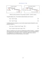
6–9. Figure P6–2 shows a synchronous motor phasor diagram for a motor operating at a
leading power factor with no R
A
. For this motor, the torque angle is given by
Derive an equation for the torque angle of the synchronous motor if the armature re-
sistance is included.
6–10. A 480-V, 375-kVA, 0.8-PF-lagging, Y-connected synchronous generator has a syn-
chronous reactance of 0.4
⍀ and a negligible armature resistance. This generator is
supplying power to a 480-V, 80-kW, 0.8-PF-leading, Y-connected synchronous mo-
tor with a synchronous reactance of 1.1
⍀ and a negligible armature resistance. The
synchronous generator is adjusted to have a terminal voltage of 480 V when the mo-
tor is drawing the rated power at unity power factor.
(a) Calculate the magnitudes and angles of E
A
for both machines.
(b) If the flux of the motor is increased by 10 percent, what happens to the termi-
nal voltage of the power system? What is its new value?
(c) What is the power factor of the motor after the increase in motor flux?
6–11. A 480-V, 100-kW, 50-Hz, four-pole, Y-connected synchronous motor has a rated
power factor of 0.85 leading. At full load, the efficiency is 91 percent. The armature
resistance is 0.08 ⍀, and the synchronous reactance is 1.0 ⍀. Find the following
quantities for this machine when it is operating at full load:
(a) Output torque
(b) Input power
(c) n
m
(d) E
A
(e)|I
A
|
(f) P
conv
(g) P
mech
ϩ P
core
ϩ P
stray
␦
ϭ tan
Ϫ1
(
X
S
I
A
cos
V
ϩ X
S
I
A
sin
)
tan
␦
ϭ
X
S
I
A
cos
V
ϩ X
S
I
A
sin
= tan
–1
(
(
V
E
A
I
A
j
X
S
I
A
X
S
I
A
cos
X
S
I
A
sin
X
S
I
A
cos
––—————–
V + X
S
I
A
sin
FIGURE P6–2
Phasor diagram of a motor at a leading power factor.
cha65239_ch06.qxd 11/5/2003 2:35 PM Page 377
470 ELECTRIC MACHINERY FUNDAMENTALS
(a) The line current I
L
(b) The stator power factor
(c) The rotor power factor
(d) The stator copper losses P
SCL
(e) The air-gap power P
AG
(f) The power converted from electrical to mechanical form P
conv
(g) The induced torque
ind
(h) The load torque
load
(i) The overall machine efficiency
(j) The motor speed in revolutions per minute and radians per second
7–15. For the motor in Problem 7–14, what is the pullout torque? What is the slip at the
pullout torque? What is the rotor speed at the pullout torque?
7–16. If the motor in Problem 7–14 is to be driven from a 440-V, 60-Hz power supply,
what will the pullout torque be? What will the slip be at pullout?
7–17. Plot the following quantities for the motor in Problem 7–14 as slip varies from 0 to
10 percent: (a)
ind
; (b) P
conv
; (c) P
out
; (d) efficiency
. At what slip does P
out
equal
the rated power of the machine?
7–18. A 208-V, 60 Hz six-pole, Y-connected, 25-hp design class B induction motor is
tested in the laboratory, with the following results:
No load: 208 V, 22.0 A, 1200 W, 60 Hz
Locked rotor: 24.6 V, 64.5 A, 2200 W, 15 Hz
DC test: 13.5 V, 64 A
Find the equivalent circuit of this motor, and plot its torque–speed characteristic
curve.
7–19. A 460-V, four-pole, 50-hp, 60-Hz, Y-connected, three-phase induction motor devel-
ops its full-load induced torque at 3.8 percent slip when operating at 60 Hz and 460
V. The per-phase circuit model impedances of the motor are
R
1
ϭ 0.33 ⍀ X
M
ϭ 30 ⍀
X
1
ϭ 0.42 ⍀ X
2
ϭ 0.42 ⍀
Mechanical, core, and stray losses may be neglected in this problem.
(a) Find the value of the rotor resistance R
2
.
(b) Find
max
, s
max
, and the rotor speed at maximum torque for this motor.
(c) Find the starting torque of this motor.
(d) What code letter factor should be assigned to this motor?
7–20. Answer the following questions about the motor in Problem 7–19.
(a) If this motor is started from a 460-V infinite bus, how much current will flow in
the motor at starting?
(b) If transmission line with an impedance of 0.35 ϩ j0.25 ⍀ per phase is used to
connect the induction motor to the infinite bus, what will the starting current of
the motor be? What will the motor’s terminal voltage be on starting?
(c) If an ideal 1.4:1 step-down autotransformer is connected between the transmis-
sion line and the motor, what will the current be in the transmission line during
starting? What will the voltage be at the motor end of the transmission line dur-
ing starting?
cha65239_ch07.qxd 11/5/2003 3:02 PM Page 470
DC MOTORS AND GENERATORS 623
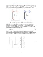
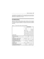
9–10. If the motor is connected cumulatively compounded as shown in Figure P9–4 and if
R
adj
ϭ 175 ⍀, what is its no-load speed? What is its full-load speed? What is its
speed regulation? Calculate and plot the torque–speed characteristic for this motor.
(Neglect armature effects in this problem.)
9–11. The motor is connected cumulatively compounded and is operating at full load.
What will the new speed of the motor be if R
adj
is increased to 250 ⍀? How does the
new speed compare to the full-load speed calculated in Problem 9–10?
9–12. The motor is now connected differentially compounded.
(a) If R
adj
ϭ 175 ⍀, what is the no-load speed of the motor?
(b) What is the motor’s speed when the armature current reaches 20A? 40 A? 60 A?
(c) Calculate and plot the torque–speed characteristic curve of this motor.
9–13. A 7.5-hp, 120-V series dc motor has an armature resistance of 0.2 ⍀ and a series field
resistance of 0.16 ⍀. At full load, the current input is 58 A, and the rated speed is
R
A
E
A
V
T
= 240 V
100
+
–
I
F
I
L
I
A
L
F
R
F
R
adj
0.40
FIGURE P9–2
The equivalent circuit of the shunt motor in Problems 9–1 to 9–7.
R
A
E
A
V
F
= 240 V V
A
= 120 to 240 V
+
–
I
L
I
F
I
A
+
–
+
–
R
F
= 100
L
F
R
adj
0.40
FIGURE P9–3
The equivalent circuit of the separately excited motor in Problems 9–8 and 9–9.
cha65239_ch09.qxd 11/14/03 10:10 AM Page 623
624 ELECTRIC MACHINERY FUNDAMENTALS
1050 r/min. Its magnetization curve is shown in Figure P9–5. The core losses are 200
W, and the mechanical losses are 240 W at full load. Assume that the mechanical
losses vary as the cube of the speed of the motor and that the core losses are constant.
(a) What is the efficiency of the motor at full load?
(b) What are the speed and efficiency of the motor if it is operating at an armature
current of 35 A?
(c) Plot the torque–speed characteristic for this motor.
9–14. A 20-hp, 240-V, 76-A, 900 r/min series motor has a field winding of 33 turns per
pole. Its armature resistance is 0.09 ⍀, and its field resistance is 0.06 ⍀. The mag-
netization curve expressed in terms of magnetomotive force versus E
A
at 900 r/min
is given by the following table:
E
A
, V 95 150 188 212 229 243
Ᏺ, A • turns 500 1000 1500 2000 2500 3000
Armature reaction is negligible in this machine.
(a) Compute the motor’s torque, speed, and output power at 33, 67, 100, and 133
percent of full-load armature current. (Neglect rotational losses.)
(b) Plot the torque–speed characteristic of this machine.
9–15. A 300-hp, 440-V, 560-A, 863 r/min shunt dc motor has been tested, and the follow-
ing data were taken:
Blocked-rotor test:
V
A
ϭ 16.3 V exclusive of brushes V
F
ϭ 440 V
I
A
ϭ 500 A I
F
ϭ 8.86 A
No-load operation:
V
A
ϭ 16.3 V including brushes I
F
ϭ 8.76 A
I
A
ϭ 23.1 A n ϭ 863 r/min
E
A
V
T
= 240 V
= Cumulatively compounded
= Differentially compounded
= R
A
+ R
S
100
+
–
I
F
I
L
I
A
L
F
R
F
L
S
R
adj
+
–
0.44
FIGURE P9–4
The equivalent circuit of the compounded motor in Problems 9–10 to 9–12.
cha65239_ch09.qxd 11/14/03 10:10 AM Page 624