Machining and Monitoring Strategies Part 3 doc
Bạn đang xem bản rút gọn của tài liệu. Xem và tải ngay bản đầy đủ của tài liệu tại đây (648.67 KB, 10 trang )
9.3 HSM – with Non-
Orthogonal Machine
Tools and Robots
Variax/Hexapod – Design Concept
Non-orthogonal machine tools such as the one simu-
lated, designed and developed for HSM applications
is typically illustrated in various ways in Figs. 223 to
225: utilising ‘virtual’ six axes kinematics (i.e. namely:
X-, Y-, Z-, A-, B- and C-axes), therefore these axes
operate without having any ‘true’ slideways. is par-
ticular kinematic concept has actuators that cross each
other forming X’s instead of meeting at apexes to form
triangles, as they occur in aircra ight simulators,
which uses conceptually similar mechanisms – known
as Stewart platforms, these congurations being a
form of ‘parallel kinematic link mechanism’ (Fig. 223).
To develop this new concept for a machine tool, the
manufacturer utilised computer-aided technology
which played a pivotal role in creating the structural
design (Fig. 223). In particular, the application of a
totally three-dimensional design environment was
employed, utilising both nite element analysis (FEA)
in conjunction with kinematic analyses. However, the
‘Variax’ design uses a range of uncomplicated, or stan-
dard mechanical components in its design. While new
forms of motion actuators were discarded in favour of
conventional and well-proven ballscrew technology,
with its accompanying motor and drive machinery.
Even the gimbals that secure the legs at the base and
the spindle carrier, are relatively simple devices.
With the design of such a high thrust machine, a
signicant problem to overcome was the connection
of the spindle to the six legs (Fig. 223a). e answer
to the connection problem was a simple space frame
design, allowing all the forces to be either in tension,
or compression along the structural elements – similar
to a bridge design. If one compared this ‘Variax design’
with that of a ‘plate-type design’ to secure the spindle
to the legs, then the former space frame concept im-
proves the mass-to-stiness ratio by 275%. While an-
other key development problem to be overcome was
that of how a spindle supported and driven by six
axes kinematically moves in space, moreover, was it
even mathematically possible to control the motional
members? For example and by way of illustration of
this complex mathematical/control problem: a simple
‘X-axis’ linear kinematic translation requires all six
legs to simultaneously move, but each leg will move at
dierent speeds, either accelerating, or decelerating at
dierent rates through the whole ‘linear movement’ –
requiring very complex multi-axes mathematical solu-
tions to achieve this action. By employing a system of
novel mathematical transformation runs in real-time
by the CNC’s multi-processor this mathematical trans-
lation action was achieved, but from a programmer’s
viewpoint, conventional ‘word-address format’
17
of
programming knowledge was all that was needed to
successful operate the machine tool.
Non-Orthogonal Versus Orthogonal
Machine Tool Designs
e ‘Variax’s’ machine capabilities and benets dif-
fer signicantly from those found on conventional
slideway-based orthogonal machine tools. So, on an
orthogonal machine the slideways must be perfectly
straight, parallel and at 90° to each other. On these
machines, an axis must have accuracy and precision
control along the slideway having linear and rotary
degrees of freedom carefully managed by the ground
way being scraped to minimise any impending errors/
uncertainties. As mentioned earlier, these orthogonal
axes have kinematically 21 degrees of freedom, with:
linear motion; rotational – i.e. yaw, pitch and roll; plus
17 ‘Word-address format’ of CNC programming, can be consid-
ered as: A system of coding instructions whereby each word in
a block is addressed by using one, or more alphabetic characters
identifying the meaning of the word. [Source: Valentino and
Goldenberg, et al. 2000]
For example, some typical ‘G- and M-codes’ are:
G00 – rapid movement/ traverse of the tool (modal);
G01 – linear interpolation (ie. tool moved at a prescribed fee-
drate) (modal);
G02 – circular interpolation clockwise – CW (modal);
G03 – circular interpolation counter clockwise – CCW
(modal);
G04 – programmed dwell (*non-modal);
G40 – Cancel cutter diameter compensation (modal);
G41 – tool diameter cutter compensation (i.e. radial-oset) on
le-hand side of workpiece (modal);
G42 – tool diameter cutter compensation (i.e. radial-oset) on
right-hand side of workpiece (modal);
M00 – Program stop;
M02 – End of program;
M03 – spindle on (CW);
M04 – spindle on (CCW).
NB Many more codes/auxiliary functions exist, utilised in
‘word-address format’ programs.*Non–modal commands are
only active in that actual block. [Source, Smith et al., 1993]
Machining and Monitoring Strategies
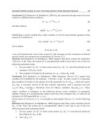
Figure 223. Basic kinematics of the non-orthogonal machine tool, with a simulated rendition of the es-
sential elements of the machine’s structure. [Courtesy of Giddings & Lewis]
.
squareness errors to be considered, if the machine tool
is to perform within its intended specication. In ef-
fect, with an orthogonal machine tool three axes are
controlled (i.e. the X-, Y- and Z-axes), and the rota-
tional and squareness parameters must be ‘perfect’.
us, these errors/uncertainties can be established by
laser-calibration, then compensated for up to a certain
extent to create and ‘stable machine’. If for example,
one considers the worst case scenario for a machine
tool conguration, namely that of a horizontal ma-
chining centre. Here, if we just deal with one axis,
then the spindle travels up and down the column’s
Chapter
face – as it moves to various points on the workpiece’s
geometry. e tooling is held here and in eect, is a
cantilevered beam (i.e. the tool is normally only sup-
ported at one end only). In this situation the tooling
assembly can be equated to that of boring tooling, then
its inherent rigidity will decrease by the cube of the
stand-o distance from the ‘gauge line’
18
. When a ma-
chine tool builder calibrates this orthogonal-designed
machine tool, they will measure along the base of the
column – either optically (i.e. by for example, autocol-
limation
19
instrumentation), or with laser interferom-
etry, thus feeding-back any potential error sources for
CNC’s dynamic compensation, during execution of
the part program. Nonetheless, the column can either
minutely: twist; bend; or even move; if its temperature
varies by only just a few °C. In fact, it has been widely
reported that up to 70% of the total errors present on a
machine tool are thermally-related.
On conventional machine tools – with slideways,
essentially one does not really know what is occur-
ring in all of the degrees of freedom at any particu-
lar time. Although even if we did know the dynamic
status, unless some form of ‘adaptive compensation
system’
20
was tted to the machine, having some so-
phisticated multiple sensors positioned on and within
critical positions on the machine’s structure, then oth-
erwise, it would be almost impossible to compensate
18 ‘Gauge line’ of the tool, is the distance from where its eective
length is taken, specically when the tool length compensa-
tion distance is needed for the CNC programming details.
Normally, this ‘gauge line’ is datumed from a known point on
the male spindle taper, located in, and standing slightly proud
of its female counterpart. is measurement is either prefer-
ably set in a tool presetting machine, or it can be obtained on
the machine tool by some form of table-mounted touch-trig-
ger cube. Alternatively, the tool’s length can also be accurately
measured by some form of laser-activated instrumentation,
strategically-positioned at a suitable part of the machine tool’s
structure – where it will not interfere with any subsequent
machining operations.
19 ‘Autocollimation’ was the ‘traditional’ technique that was em-
ployed for any form of machine tool calibration. Autocollima-
tion instruments and equipment, utilise highly-evolved ac-
curate and precision optical apparatus to measure alignments
and squarenesses of the machine tool’s axes, which can then
be utilised to compensate for any error sources detected in the
machine tool’s kinematics. [Sources: Taylor Hobson, 1984/
Spectrum Metrology, Leicester (UK)]
20
‘Adaptive error compensation’ , basically utilises sophisticated
geometric algorithms that allow for compensation of the geo-
metrical elements, via a range of strategically-positioned sen-
sors on orthogonal machine tools. (Source: Ford, 1993)
for such error sources – as they occur. Clearly then, it
is no coincidence that both the ‘Variax’ operates with
six legs and, it also has six degrees of freedom. ese
leg orientations have three pairs of two legs that cross
each other and which are secured, but free to swivel
at either end (i.e. see the simulated renditions in Fig.
223 and partial assembly of an actual ‘Variax’ machine
tool in Fig. 224). With these six legs, all of the degrees
of freedom are controlled, which in turn, eradicates
the usual sources of errors exhibited by conventional
multiple and ‘stacked’ slideway axes. Some of the ma-
jor benets obtained from the ‘Variax’s’ design congu-
ration are:
•
Extremely rigid machine tool – coupled to small
mass making it 500% more rigid than a conven-
tional machine, due to the fact that all forces
whether they are in compression, or tension are fed
through the six legs and its associated space frame,
•
Exceedingly fast in operation – as all the ballscrews
must move together, they only have a light mass to
contend with, making it up to 5 times faster than an
orthogonal machine tool,
•
Very high continuous thrust – due to concurrent
and synchronised use of the six ballscrews,
•
High accuracy and precision – this is due to the
machine’s inherent rigidity, coupled to the fact that
all six degrees of freedom are controlled, with laser
feedback through the centre of the ballscrews
21
,
•
No supporting structure – the ‘Variax’ is self-con-
tained, so it does not need foundations. e ma-
chine has a three-point location and the weight
of the spindle head is neutralised, as far as the
ballscews are concerned – by the three large gas-
spring supports
22
(i.e. see Figs. 224 and 225a).
21 ‘Laser-controlled feedback’ , through the centre of the
ballscrews, negates the Abbé oeset error, with any errors in
the legs (i.e. axes) being averaged, rather than ‘stacked-up’ as
is the situation in conventional machine tools. Hence, volu-
metric accuracies are in line with that of a Co-ordinate Meas-
uring Machine CMM – see details in Fig. 223a.
22 ‘Gas-spring supports’ , are tted outside the actuator platform
(i.e. see Figs. 224 and 225a), they are strategically positioned
so that they carry actuator platform’s gravity-induced
load. us, these gas-spring support placements and their
operation, means that the actuators have to only overcome
inertia and momentum to move the machining head. is
has the kinematic benet of enabling the machine spindle to
move through space faster than any single actuator changes
its length, this combination allows the ‘Variax’ to move and
accelerate up to ve times faster than a conventional machine
tool.
Machining and Monitoring Strategies
NB e machine tool also has large rubberised
compliance mountings, so when it is in operation
it seems to ‘visually-bounce around’ , but this is
something of an optical illusion, as the overall rigid
integrity of the ‘Variax’ is maintained.
Variax/Hexapod – Specification
and Machining Performance
e ‘Variax’ is equipped with a 630 mm square pallet
and can both move and cut at 66 m min
–1
(i.e. see Fig.
225b), accelerating at >1g while providing >3 tonnes
of continuous thrust in the Z-axis. e machine tool is
compliant with Standard: ASME B5.54, obtaining ac-
curacies of <10
µm, while its rigidity is >175 Nm µm
–1
.
Pallet change time is 10 seconds, with a tool change
time of 6 seconds (chip-to-chip), having a tool stor-
age capacity of 50 tools (i.e. expandable). e standard
tool spindle cartridge is rated at 22 kW , with spindle
speed ranging from 100 to 16,000 rev min
–1
, having an
angle of tool spindle inclination of up to 25°.
In demonstrations and in-house trials at the man-
ufacturer’s premises, the initial prototype ‘Variax’ ma-
chine was operated and machining components for
three years. On one large aerospace machining appli-
cation of a critical component, the original cycle-time
was 19.3 hours on a conventional machining centre,
but when this same part was cut on the ‘Variax’ , it took
just 3 hours to complete, with the additional benet of
being both more accurate and precise. Equally, when
a smaller aerospace component – a landing bracket –
was originally machined it took 1.65 hours on the con-
ventional machine tool, but when the same part was
placed on the ‘Variax’ , it took only 0.55 hours cycle-
time to complete.
Figure 224. The Variax/
Hexapod Machining Cen-
tre here seen during nal
assembly at Nottingham
University, equipped with
an up-rated high-fre-
quency spindle: 40,000 rev
min
–1
@ 40 kW power-rat-
ing, with a ski taper.
NB
Laser transducers –
giving an accurate and
precise control, can clearly
be seen located on each
of the actuator legs.
[Courtesy of Giddings &
Lewis/The University of
Nottingham (UK)]
.
Chapter
Figure 225. Variax/Hexapod oers a unique and rigid design solution, with many production benets. [Cour-
tesy of Giddings & Lewis]
.
Machining and Monitoring Strategies
e capital outlay for a ‘Variax/Hexapod’ machine
tool, costs about the same as a similar specication –
component size capacity, to that of a conventional ve-
axis machining centre, but with the above additional
performance benets.
Robotic Machining
Robotic machining applications have been utilised for
some years, currently up to a thousand such installa-
tions are to be found world-wide. Probably the biggest
user of robotic machining is the aerospace industries,
although the automotive industry is catching up fast.
Most of the current research work into robot machin-
ing is undertaken with an anthropometric type of
robot conguration, usually having either ve, or six
axes (i.e. see Fig. 226).
If a six axis robot is employed (Fig. 226), it gives
several benets over say, a ve-axis machining centre,
with probably the greatest production advantage being
access to the workpiece’s surface features (Fig. 226b).
is extra degree of freedom, allows the alternative
wrist positions to achieve identical tool positional
orientation – regardless of the workpiece contour,
enabling the robot axis the ability to rotate the wrist
about the tool’s axis. Moreover, where speed and ac-
celeration are important, robots normally out-perform
the more traditional machine tool structures, mainly
due to both their low weight and minimal inertial ef-
fects. Within the robot’s programming language, pa-
rameters exist that allow a balance to be made between
robotic arm speed and accuracy. So, when roughing-
out higher speeds can be employed – at the expense
of accuracy, then the parameters can be changed to a
slower speed, but with greater nished machined part
accuracies.
Limitations also occur when using robots for ma-
chining, with perhaps the most obvious one being
their intrinsic lack of rigidity, when compared to that
of virtually any machine tool. If a robot is employed
at conventional spindle speeds the tool’s cutting forces
are simply too great, creating both vibrations and de-
ections in the robotic arm, which badly impacts on
the component’s machined surface texture and di-
mensional accuracy. In order to mitigate against any
cutting force and accuracy deciencies, it is essential
to utilise HSM spindles, in combination with taking
small D
OC
’s, to minimise these eects.
e robot’s kinematic structural complexity also
causes positional problems, due to innate manufactur-
ing tolerance eects to the location of the joints in the
robotic arm. is dimensional and geometric toler-
ancing build-up, means that the mathematical model
used to control individual joint positions in space,
will minutely dier from the actual reality to that of
the joint placements. is positional dierence being
most apparent and exaggerated around the perimeter
of the robot’s working envelope. Oen, it is impossible
to calibrate the mathematical model for these com-
plex inter-related errors, as the overall complexity of
robot’s control algorithms then become such that they
cannot execute the kinematic motions fast enough to
dynamically control the robot at the required axis tra-
jectories.
In calibration trials on a typical six-axis anthropo-
metric robot undertaken by Young (1999) while work-
ing in cartesian co-ordinates for the robot’s positional
accuracy – when assessed with laser interferometer
instrumentation, the results produced linear errors of
± 0.8 mm in each cartesian co-ordinate (i.e. X-, Y- and
Z-axes) – across the complete working range. e er-
ror curves produced were in fact, symptomatic of the
kinematic structure of these robots. Characteristics
included a decrease in backlash to almost zero – to-
ward the perimeter of the working envelope (i.e. due
to gravitational eects), while a combination of linear
and sinusoidal eects combined to produce the total
error. Even though these robot errors are large with
respect to those found on a machine tool, they should
not deter robotic usage for suitable HSM applications.
e repeatability shown by most robots is usually far
superior to that of its accuracy.
In practice, any multiple axis robotic arm utilised
for sculptured machining applications, needs to have
their axes biased and oset in order to eliminate the
‘paradox’ that might overwhelm them when all axes
are attempting to keep the end-eector (i.e. tool) nor-
mal to the contoured surface (Fig. 226b). For example,
on a three-roll wrist (Fig. 226), the combination of the
kinematic linear and rotational build-up, may result
in instead of one of these axes angularly moving just
1°, it causes it to actually move 359° instead – thereby
scrapping the workpiece in the process! To alleviate
this problem, if the workstation/stand, is oset to one
side and angled, this oset and compound angle will
minimise the axis predicament that can aict the ro-
bot’s subsequent programmed motions. e worksta-
tion position in its ‘known space’ with respect to the
robot axes datums must be known and accurately cali-
brated, thus ensuring that the angled grid-plate for re-
sulting workpiece xturing is both ‘xed and qualied’.
By slowing down the robotic axis trajectories in the -
Chapter
Figure 226. Robotic high-speed machining with a multi-axis anthropometric robot, equipped with HSM
milling head. [Courtesy of Southampton Solent University/Westwind Air Bearing Ltd./Smith, G.T.]
.
Machining and Monitoring Strategies
nal machining passes over a sculptured workpiece sur-
face, a certain degree of accuracy can be achieved, but
even here, it does not approach that of any moderately
accurate and precise machine tool. Tool centre-point
programming is the preferred option, as when utilising
cartesian co-ordinates, the programmed points repre-
sent the cutter’s end – once the required oset has been
established. is tool centre-point program allows the
programmer to eectively disregard the tool’s length
in any subsequent machining applications. However,
care must be taken with any exible coupling connec-
tions, such as pneumatics, water, or electrical wiring
to the HSM spindle – allowing sucient slack in the
piping (i.e see Fig. 226), thus ensuring that the robot
will not inadvertently de-couple these services, as it at-
tempts to manufacture the complex part.
9.4 HSM – Toolholders/
Chucks
Introduction
Rotational speeds for tooling assemblies subjected to
HSM applications must of necessity be very high, this
can create several problems for any tooling utilised in
such machining activities. Notably, due to the centrif-
ugal force the toolholder could swell and slacken its
gripping force on the tool’s shank. In an extreme situa-
tion due to the application of cutting forces this might
cause the tool to speedily exit from its holder, in so do-
ing either scrapping the workpiece, or become a severe
safety hazard to any operator in attendance at the ma-
chine tool. erefore, both a good t and connection
is an essential requirement of any HSM machining ap-
plication. us, the mechanical interface between the
toolholder and the machine’s spindle, together with
that of the tool’s shank and its respective toolholder
are the prerequisites for a successful HSM application.
.. Toolshank Design
and Gripping Pressures
Tool and Sleeve – Mechanical Interface
e latter point briey mentioned in the previous
section concerning the tool shank’s tment in the
holder, is an important criterion in any HSM applica-
tion. Nonetheless, of greater interest and note, is the
actual gripping pressure exerted at the toolholder’s
mechanical interface with its mating tool shank. Some
interesting toolholder designs have been attempted to
increase the gripping pressure here, with the level ex-
erted at the free-end of the holder not being too great
a problem, due to elastic compliance of the sleeve in
this region. e notable diculty arises as the shank
is being gripped toward the ange end of this sleeve,
where with most conventional toolholder sleeve de-
signs, the gripping pressure drops-o signicantly at
this locality. At high rotational speed and under the
application of the cutting forces, the cutter will tend
to become unstable and present a distinct ‘wobbling
motion’ due to the lack of gripping pressure and sup-
port here, being exacerbated by the higher imparted
centrifugal forces. In order to try to alleviate this lack
of grip problem, signicant design eort has been
expended over the years to attempt to increase elas-
tic behaviour and hence amplify gripping pressure at
this sleeve’s region. In the graph shown in Fig. 227b,
the elastic behaviour and its associated contraction are
plotted from the tool sleeve’s free-end in linear steps
along the sleeve and toward the ange. In most prior
designs the sleeve contraction on the tool’s shank near
the ange was approximately 50
µm (i.e. shown by plot
‘B’). By introducing a radially-plunged undercut to the
sleeve’s outside diameter at the juncture of the ange
and sleeve (i.e. see Fig. 227a), this creates signicantly
increased elastic behaviour and hence improved grip-
ping pressure at this region of the sleeve, as illustrated
by the plotted relationship of the test results – produc-
ing a sleeve contraction of 145
µm at the ange, as in-
dicated by ‘A’ , in Fig. 227b. is vastly improved grip
-
ping pressure with the ‘undercut ange’ is of the order
≈150%, when compared to other design techniques,
which restricts any attempt at the tool’s ‘wobbling be-
haviour’ as a result of the improved elastic contraction
on the shank.
In order to obtain a good overall elastic gripping
pressure along the length of the sleeve, multiple hard-
ened needle rollers are positioned – at a slight angular
inclination, both around and along the male shallow-
angled tapered sleeve’s periphery (i.e. items 2 and 4 in
Fig. 227a). As the female tapered sleeve (item 3) is ro-
tated, the caged inclined needle rollers rotate and be-
gin to steadily move up the male tapered sleeve toward
the ange (item 1) and, in so doing, elastically com-
press the sleeve (item 2), which in turn will tighten
on a tool’s shank. As the tapered female sleeve (item
3) is fully tightened with its ‘C-spanner’ , it will com
-
Chapter
Figure 227. High-speed milling toolholders (chucks), holding cutter’s shank along its whole gripping length. [Courtesy of Di-
ashowa Tooling]
.
Machining and Monitoring Strategies
press its face against the rubberised contact seal and
the ange (item 1), thereby acting as both a vibration
damper and sealing against particle/debris ingress into
the mechanism. e front face already being sealed
against such potential particle ingress (i.e. see Fig. 228
sectional detail diagram). In order to increase the elas-
tic behaviour of the male tapered sleeve (item 2 – Fig.
227) and improve its gripping pressure here, the end of
the sleeve is partially slit along its length and around
it at eight equally-spaced positions (i.e. see Fig. 228).
is mechanical design solution for the tightening of
the male tapered sleeve, gives possibly the optimum
gripping pressure for such a mechanical interface on
the tool’s parallel shank.
Tool and Sleeve – Hydraulic Designs
For an alternative tool-gripping pressure design con-
cept, the hydraulic toolholder (i.e. see Fig. 228 – top
right – for a section through the tool sleeve), oers an
ideal alternative to the mechanical tool interface previ-
ously mentioned above. Here, the hydraulic toolholder
manufacturer guarantees a 0.005 mm tolerance-in-
roundness (TIR) at 100 mm from the front face, with
<0.0013 mm repeatability for such hydraulic toolhold
-
ers. e normal contraction for a φ25 mm toolholder is
<0.13mm, although the contraction is proportionally
higher for larger diameters, conversely, it will be lower
for smaller diameters. e benets of utilising hydrau-
lic toolholders are that they provide both rigidity and
balance, while holding the tool’s shank axially-straight
along its own centreline. It is also claimed that hydrau-
lic toolholders produce less vibrations resulting in im-
proved machined surface textures, with a possibility of
less chatter. is latter benet it is claimed to be the
result of the hydraulic uid in the toolholder acting as
a natural vibration damper and impact cushion.
Hydraulic toolholders are balanced to ISO/ANSI
Standards, to G2.5 at 15,000 rev min
–1
in practice, but
are claimed to perform successfully in spindles rotat-
ing at 50,000 rev min
–1
. Moreover, other benets are
made that tool presetting is much quicker to achieve
than mechanical designed toolholder assemblies, as it
is stated that due to the hydraulics having an automatic
centring action, only the tool’s length needs to be pre-
set. Further, as there are fewer moving parts, these
toolholders need little maintenance and the sleeve and
piston should have a fatigue life of >100,000 cycles,
prior to servicing, this ‘in-service life’ representing
many years of practical usage.
e disadvantages to hydraulic toolholders are few,
but may prove a signicant obstacle to their introduc-
tion, including the fact that their purchase costs are
higher than their mechanical counterparts, with the
other limitation being a new hydraulic sleeve is re-
quired for dierent tool shank diameters. However,
this latter point can be mitigated against, by conduct-
ing a programme of: rationalisation; consolidation;
and optimisation on the various production require-
ments for toolholder varieties and shank diameters
(i.e. see Chapter 1, Sections 1.1.1 to 1.1.3 for details of
such tool survey).
Tool and Sleeve – Thermal and Cryogenic Designs
Shrink-t systems require specially made tool hold-
ers, being designed for a specic tool shank diameter,
although they can accommodate any style of shank.
Once in-situ the tool in its thermal sleeve behaves in
a very similar way to that of a one-piece tool. e high
gripping pressure coupled to excellent concentric-
ity (i.e. <5
µm), allows these toolholders to increase
speeds and feeds by >20%, when compared to most
of their mechanically-designed counterparts. Due to
greater rotating concentricity of shrink-t toolholders,
there is a better wear pattern developed on the milling
cutter’s teeth, or drill’s lips, etc., which it is claimed,
increases tool life by >30% over conventional tool-
holders. In a similar fashion to that of hydraulic tool-
holders, thermal contraction occurs both around the
periphery and along the whole mechanical interface,
which will automatically centre the tool’s shank within
its mating bore. is complete toolholder-to-tool t-
ment, minimises centrifugal force when operating in
an HSM mode. us, the contraction of the toolholder
rigidly locks the tool in-situ, this gripping pressure is
at least 500% greater than for conventional toolhold-
ers. In fact the pressure exerted here, is even greater
than that of the pull-stud (i.e. retention knob), mean-
ing that in the presence of high forces, the whole as-
sembly would be pulled out of the spindle before the
tool would be released by its mating holder.
e signicant component of a shrink-t toolhold-
ing system is the induction heating unit, as schemati-
cally depicted in Fig. 229a. Typically, the solid-state
and self-contained unit is relatively compact and in
operation to change tools, the user positions the tool
holder in a receptacle built into a shelf at the front of
the unit. An induction coil is located beneath the shelf
and encircles the toolholder’s sleeve (i.e. collar), which
Chapter