Introducing 3ds Max 9 3D for beginners apr 2007 - part 7 pptx
Bạn đang xem bản rút gọn của tài liệu. Xem và tải ngay bản đầy đủ của tài liệu tại đây (1.71 MB, 55 trang )
Later in the chapter, you will learn a more efficient way to edit the image on the
object, known as UVW mapping.
Opacity Maps
Opacity mapping allows you to cut out parts of an object by making those parts invisible.
You can also create wonderful fading effects using Opacity maps. With opacity mapping,
you don’t have to model certain details, which can be a real time saver. In this example,
you will create a chain link fence. However, you will not model a fence. You will create it
entirely from mapping. To make a chain link fence, follow these steps:
1. Open the
Chain Link Opacity Map.max file in the Texture Scene Files folder on the
companion CD. Open the Material Editor and select a sample slot. First, you are going
to add a bitmap to the diffuse color, so go to the Maps rollout. Select the bar next to
Diffuse Color. Pick Bitmap from the Material/Map browser and navigate to the Tex-
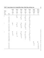
ture Scene Files folder on the CD. Choose Chain Link.tif (shown in Figure 7.41).
2. Go to the Coordinates rollout and change both the U and V Tiling parameters to 3.0.
This will scale down the image because the image repeats three times.
3. Apply the Material to the Plane geometry in the scene. Click the Show Map in View-
port button. Render and you will see something similar to Figure 7.42. As you can
see, the Chain Link image appears on the plane, but you can’t see the objects on the
other side.
Figure 7.42
The chain link fence
is rendered.
more mapping exercises ■ 313
Figure 7.41
The chain link
texture
97612c07.qxd 2/26/07 2:56 PM Page 313
4. Go to the Material Editor. Click the Go to Parent button to get to the Maps rollout for
the parent material. Click on the bar next to Opacity and select Bitmap from the
Material/Map browser. In the Explore window, navigate to the Texture Scene Files
folder on the CD and select Chain Link OP.tif (shown here).
5. The tiling values for the Opacity map must be the same as the diffuse map; otherwise
the transparency of the fence will not line up with the links of the fence. Go to the
Coordinates rollout, and change both the U and V Tiling to 3.0. Render to see the
results shown here.
You can see immediately how useful opacity mapping can be. 3ds Max uses the white
portions of the image map to display full opacity, whereas the black areas become trans-
parent. If you did not have an opacity file such as the one in this exercise, you could easily
create one by painting a black-and-white matte of the color image that you are using for
the material.
314 ■ chapter 7: Materials and Mapping
97612c07.qxd 2/26/07 2:56 PM Page 314
Mapping Coordinates
An image map is a two-dimensional entity that has length and width but no depth, while
geometry in 3ds Max extends in all three axes. How is a material, which contains 2D image
maps, applied properly to a scene object? Are the maps projected in a single direction onto
the object’s surfaces or do they envelop the object cylindrically or spherically? The answer
depends on the type of mapping coordinates applied to the object. Mapping coordinates
define how and where image maps are projected onto an object’s surfaces and whether the
maps are repeated across those surfaces.
Mapping coordinates are applied to objects in several ways. When primitive objects are
created and the Generate Mapping Coords option is checked, at the bottom of the Para-
meters rollout, the appropriate mapping coordinates are created automatically. The Gen-
erate Mapping Coords option is on by default.
Loft objects, which are covered in Chapter 5, control mapping in the Mapping section
of the Surface Parameters rollout. The Length Repeat value determines how many times
the material’s maps are repeated along the length of the Path object, and the Width Repeat
value determines how many times the maps are repeated around the shape object. The
configuration of the shape or path object is irrelevant to the application of the mapping
coordinates; the loft object can create mapping coordinates for any loft object. Figure 7.43
shows a loft object with a simple checker pattern repeated five times along the object’s
length and three times around the perimeter of the shape.
Figure 7.43
A loft object control-
ling a checker map’s
repetition in the Sur-
face Parameters
rollout
mapping coordinates ■ 315
97612c07.qxd 2/26/07 2:56 PM Page 315
The UVW Map modifier is a common method for applying and controlling mapping
coordinates. You select the type of mapping projection, regardless of the shape of the
object, and then set the amount of tiling in the modifier’s parameters. The mapping coor-
dinates applied through the UVW Map modifier override any other mapping coordinates
applied to an object, and the Tiling values set for the modifier are multiplied by the Tiling
value set in the assigned material.
Assign the UVW Map Modifier
Now let’s take a look at how to apply a UVW Map Modifier in a scene. The following
exercise examines the use of the UVW Map modifier:
1.
Open the UVW.max file in the Texture Scene Files folder on the companion CD. This scene
consists of a wall object with a linked window and two significantly different boxes.
MAPPING COORDINATES AND BOOLEANS
Boolean compound objects handle mapping in their own unique ways. When only Operand A has a mapped material,
that material and its mapping coordinates are inherited by the resultant Boolean object. When only Operand B
has a mapped material, the option of applying that material and mapping
appears in the form of a dialog box. When both operands have mapped
materials, the Material Attach Options dialog box presents several options
to use or discard the materials and mapping.
Objects that have been collapsed or converted to editable polys, editable meshes, or editable
patches do not have inherent mapping coordinates. They must have the UVW Map modifier
applied to utilize mapped materials.
316 ■ chapter 7: Materials and Mapping
97612c07.qxd 2/26/07 2:56 PM Page 316
2. Open the Material Editor and then assign the Brick Wall material to the wall object.
The material appears on the object in the Camera01 viewport.
The problem is that the long wall is approximately 17 feet long and the short wall is
approximately 7 feet long, and the Brick map used in the material is only eight bricks
wide. The default mapping coordinates for a wall object applies the entire map to any
vertical surface of the wall, regardless of how long that wall is. The long wall has eight
bricks stretched along its length, just as the shorter wall does.
3. Select the wall. In the Modify panel, expand the Modifier List and then select the
UVW Map modifier.
The mapping changes and now appears to streak vertically, as shown in Figure 7.44.
This is because the default Planar mapping type projects the map onto the object parallel
to the plane-shaped gizmo. The vertical lines that appear are the same color as the brick
image’s pixels where the surface of the object intersects the gizmo. To fix the issue, con-
tinue with the following steps:
mapping coordinates ■ 317
97612c07.qxd 2/26/07 2:56 PM Page 317
UNDERSTANDING UVW MAPPING
The UVW Map modifier consists primarily of a yellow gizmo that determines how the image
maps are projected onto the surfaces of an object. The images are projected outward or
inward from the gizmo and extend through the assigned objects to all surfaces. The size and
orientation of the gizmos affect how the maps are projected onto the relevant objects. The
properties of the different mapping types are listed here:
• Planar—Projects the image maps perpendicular to the perimeter of the rectangular
gizmo.
• Cylindrical— Projects the maps outward from the center of a cylindrical gizmo as if the
map were wrapped around the object in two axes.
• Cap—Projects the maps to the end caps of the cylindrical gizmo in a planar fashion.
• Spherical—Projects the maps outward from the center of a spherical gizmo as if the
map were completely enveloping the object. The top and bottom of the image maps
are gathered at the poles of the gizmo and may cause some distortion.
• Shrink Wrap—Similar to the Spherical method, except that the four corners of the
image map are gathered at a single location.
• Box—Projects the image in six perpendicular planes from the center of the gizmo.
• Face—Applies the image maps to each face of an object regardless of their size or
orientation.
• XYZ to UVW—Used with procedural maps, such as Noise or Smoke, to control the
maps when the object changes size.
Figure 7.43
The rectangular Pla-
nar mapping gizmo
causes the map to
streak vertically.
318 ■ chapter 7: Materials and Mapping
97612c07.qxd 2/26/07 2:56 PM Page 318
4. In the UVW Map modifier’s Parameters rollout, select the Box option. The mapping
changes to the same state that it was prior to applying the modifier in the first place,
indicating that the Box mapping method is the default type for wall objects.
5. In the Parameters rollout, increase the Width value until it is equal to the Length
value. This increases the size of the bricks on the shorter wall to match those on the
longer wall.
6. Change the U Tile value to 2.5 and the V Tile value to 1.5. This causes the Brick maps
to repeat two and a half times horizontally and one and a half times vertically.
mapping coordinates ■ 319
97612c07.qxd 2/26/07 2:56 PM Page 319
Acquire Mapping Coordinates
In many situations, a material needs to appear the same when applied to several different
objects. For example, two different sections of a roof may need to appear with identical map-
ping even though they are different sizes. The UVW Map modifier includes the Acquire tool
for matching one object’s mapping gizmo to another’s, as shown in the following exercise.
1. Select the BoxShort object.
2. Assign the Brick Wall material and then apply the UVW Map modifier to it. Choose
the Box mapping method in the Parameters rollout. The Brick material appears on the
box, showing all eight bricks on each side. The bricks are not the same size as those on
the wall; this may be more apparent in a rendered view.
3. In the Alignment section of the Parameters rollout, click the Acquire button and then
select the wall object.
4. In the Acquire UVW Mapping dialog box, make sure that Acquire Relative is selected
and then click OK. Acquire Relative uses the same settings as the target object’s gizmo,
but it places the gizmo around the current object. Acquire Absolute uses the same set-
tings as the target object’s gizmo, and it co-locates the current gizmo with the target
object’s gizmo.
320 ■ chapter 7: Materials and Mapping
97612c07.qxd 2/26/07 2:56 PM Page 320
5. The box’s UVW Map modifier’s gizmo Size and Tiling values change to match those
of the Wall object. Rendering the scene clearly shows the matched mapping between
the two objects.
Locating the Modifier in the Stack
As with any other modifier in the modifier stack, the UVW Map modifier is applied to the
result of the modifier or object below it in the stack. This must be considered when you
are locating the modifier or the preferred result may occur. For example, Box mapping has
a different result when it is applied to a box before it is bent than when it is applied after it
is bent.
1. Select the BoxTall object and clone it to the right. Be sure to make the clone a copy,
rather than an instance or a reference.
2. Apply the Checker1 material to both of the objects.
3. Select the original BoxTall and apply the UVW Map modifier. Choose the Box Map-
ping option.
The Fit option, in the Alignment section of the UVW Map modifier’s Parameters rollout,
shrinks or expands the gizmo to match the extents—or the overall size—of the objects.
mapping coordinates ■ 321
97612c07.qxd 2/26/07 2:56 PM Page 321
4. Apply a Bend modifier to the box. Set the Angle to 90 and the Direction to –270. The
checker pattern follows the curvature of the newly bent box.
5.
Select the second box and apply the Bend modifier with the same settings used in Step 4.
6. Apply the UVW Map modifier and select the Box mapping type. The gizmo in this
case fits the extents of the bent box, and not the original box object, resulting in a dif-
ferent layout for the checker pattern.
As you can see, the location of the UVW Map modifier in the stack impacts the final
appearance of the objects.
322 ■ chapter 7: Materials and Mapping
97612c07.qxd 2/26/07 2:56 PM Page 322
Summary
Creating materials for your objects is the next step after modeling them. Creating materi-
als can give you a sense of accomplishment because it is essentially the last step in making
the object look as you envisioned—aside from lighting and rendering, of course.
In this chapter, you learned the basics of materials, what kinds of materials are in 3ds
Max, and how to create and edit them in the Material Editors. Then, you learned how
choosing the right type of shader will make your surface look right, and then how to apply
your knowledge to mapping a pool ball, reflections and all. Next, you learned a few more
tricks of the Material Editor and all about the different kinds of maps available in 3ds Max.
With that, you created a bump map and an opacity map.
There are several ways to create materials, from simple colors to complex mappings on
distinct parameters. Finding the right combination of maps, Shader types, and Material
types can make a world of difference in the look of your scenes. It’s important to remem-
ber, like everything else in CG, texturing takes time, and gaining wisdom with your mate-
rials and maps will come with practice.
summary ■ 323
97612c07.qxd 2/26/07 2:56 PM Page 323
97612c07.qxd 2/26/07 2:56 PM Page 324
Introduction to Animation
The best way to learn how to animate is to jump right in and start animating.
You will begin this chapter by picking up the Mobile exercise from Chapter 2, “Your First
Max Animation,” and adding animation to the shapes of the mobile. You’ll take a good
look at 3ds Max’s animation tools so you can start editing animation and training your
timing skills.
Topics in this chapter include:
■
Hierarchy in Animation
■
Using Dummy Objects
■
Bouncing a Ball Using the Track Editor
■
Track View
■
Anticipation and Momentum in Knife Throwing
CHAPTER 8
97612c08.qxd 2/26/07 2:58 PM Page 325
Hierarchy in Animation: The Mobile Redux
Do you remember way back when you were reading Chapter 2? Those were good times,
weren’t they? After setting up the mobile in that exercise, you animated only the bars to
rotate, but you left the rotation of the shapes for later. In this chapter, you’ll pick up where
you left off with the mobile from Chapter 2 and finish the animation using the hierarchies
that were set up in that exercise.
You can begin this exercise by using your own Mobile file from Chapter 2, or you can
open
Mobile_v05.max from the Scenes folder in the Mobile project on the companion CD.
This scene file is the same as the file you ended up with in Chapter 2 (Mobile_v04.max),
with the exception that this version takes the animation of the bars to frame 100 instead of
frame 50 as in version 4 of that file.
If you haven’t already done so from the previous Chapter 2 exercise, copy the Mobile
project from the companion CD to your hard drive. Set your Max project folder by choos-
ing File
➔
Set Project Folder and selecting the Mobile project that you copied from the CD
to your hard drive.
Animating the Shapes
With the Mobile_v05.max scene open (or your own file), scrub through the animation to
become familiar with the scene. The intent here is to create a hierarchy in the mobile
and animate the bars. Now you will add rotation to the shapes hanging from the bars.
Figure 8.1 shows the mobile in mid-animation.
To add animation to the shapes under the bars, follow these steps:
1. Go to frame 1 of the animation, and click the Auto Key button ( ) at the bot-
tom of the UI.
2. Select the triangle hanging from the bottom bar, and go to frame 50. Rotate the triangle
in the Z-axis in either direction at least a full turn of 360 degrees, if not a lot more, as
shown here. Don’t scrub your animation yet.
3. Still at frame 50, select the square on the bar above, and rotate that shape in the Z-axis
several hundred degrees in either direction. Figure 8.2 shows the rotation of the square.
The bottom bar goes along with the square’s rotation because this is how they were
linked in Chapter 2. Don’t scrub your animation yet.
If you skipped the Mobile exercise in Chapter 2, you may want to try it now before you move
on with this animation exercise. Understanding hierarchies and how they work in animation
is extremely important.
326 ■ chapter 8: Introduction to Animation
97612c08.qxd 2/26/07 2:58 PM Page 326
4. Still at frame 50, select the star and rotate it several hundred degrees on the Z-axis in
either direction, as shown here.
Now scrub your animation and check the results. In theory, all the bars should rotate
and so should the shapes hanging on the bars. When you scrub, however, you’ll see a big
issue crop up that doesn’t seem to make sense. The mobile will seem to have lost its mind.
The shapes will rotate completely off axis, as if you set rotation keyframes on the X- and Y-
axes as well as the intended Z-axis. The same will occur with the lower bar. It will go off its
axis and rotate in an unpredictable manner. This behavior is explained in the next section,
with easy solutions to fix the issue.
Making a Mistake
Why would we pick an example to show you an incorrect workflow? Learning from
missteps is as important to learning CG as learning the correct steps. Being able to trouble-
shoot is essential to becoming good in CG, and the more trouble you get yourself into, the
better you will become at digging your way out.
Figure 8.2
The square is rotated, and its child bar
goes along for the ride.
Figure 8.1
The mobile is back!
hierarchy in animation: the mobile redux ■ 327
97612c08.qxd 2/26/07 2:58 PM Page 327
This example of strangely rotating hierarchies is an isolated issue that is loosely called
gimbal lock in many CG circles. Different CG packages have different ways of interpreting
exactly how an object rotates when it is rotating along more than one axis. Imagine three
cars all staring each other down at a three-way intersection—with the traffic light out.
Who goes first in this situation is important to the flow of traffic at the intersection. When
a 3d package calculates rotations, it needs to know which axis to rotate first before tending
to the rotation of the other axes. In 3ds Max, the animation controller is the traffic light,
directing the animation. With gimbal lock, you have an incorrect interpretation of the
rotations, so the resulting animation seems off axis.
In this exercise, the multiple rotations inherited by the children shapes and bars from
their parents caused havoc with their own rotations, so the axes became confused and
everything looks just plain wrong. The easiest way to fix this issue is to reassign the anima-
tion controllers in charge of the rotations for those objects to one that will not lock up.
Animation Controllers
By default, 3ds Max assigns a Euler XYZ controller to the rotations of objects. This is by
far the best controller to use because it gives you the best bang for the buck, as it were. In
this example, however, it doesn’t quite work. To assign a different controller, follow
along here:
1. Select the square; you will start with that object. Switch to the Motion panel (click the
Motion Panel tab ( ) in the Command panel, as you see in Figure 8.3. Open the
Assign Controller rollout. You’ll see that the Rotation controller for the square is set
to Euler XZY.
2. Select Euler XYZ from the list in the Motion panel, as shown in Figure 8.3. Click
the Assign Controller button ( ) to open the Assign Rotation Controller win-
dow shown here. Choose TCB Rotation from the list. If you do not first select the
controller from the Controller List, the Assign Controller button will be grayed out
and unusable.
3. The square and the bar linked beneath it should snap back into axis. Scrub the ani-
mation, and you’ll see that the square and the bar beneath it are not behaving as
you would expect: they are rotating on the Z-axis only, as they should. Figure 8.4
shows the resulting animation. Notice that the star and triangle are still rotating
off axis.
4. Select the triangle and repeat Steps 2 and 3 to assign a TCB Rotation controller to
the triangle. Do the same for the star. Figure 8.5 shows the proper rotations of the
shapes and the bars—but looks are deceiving. We’re not done yet!
328 ■ chapter 8: Introduction to Animation
Figure 8.3
The Assign Con-
troller rollout in the
Motion panel
97612c08.qxd 2/26/07 2:58 PM Page 328
If Euler XYZ caused such a ruckus, why isn’t TCB Rotation the default for rotating
objects? For one thing, the editing options you have with a Euler XYZ controller are head
and shoulders above what you get with TCB Rotation. With the Euler XYZ, 3ds Max splits
the X, Y, Z rotation animation into three separate tracks to give individual control over
each axis. This is ideal.
In addition, the TCB Rotation has taken the several hundred degrees of rotation you
have animated, and cut it down to within 180 degrees of rotation at most. The square, tri-
angle, and star don’t seem to be rotating the several hundred degrees you intended.
Editing the TCB Rotation Keyframes
To fix the fact that the objects do not rotate the several hundred degrees you want, you
will have to manually edit the controller to allow a greater degree of rotation:
1. Select the square and open the Key Info rollout, as shown here.
It is not a good idea to change the default animation controllers solely based on your experi-
ence with this exercise. If you run into a gimbal lock situation in the future, you’ll have a good
idea what caused it, and you’ll be able to troubleshoot it quickly.
Figure 8.5
The mobile seems to rotate properly, but does it really?
Figure 8.4
You’ve fixed the rotation of the square and its children.
hierarchy in animation: the mobile redux ■ 329
97612c08.qxd 2/26/07 2:58 PM Page 329
2. The Key Info rollout shows you the properties of the animation on the selected object
on a key-by-key basis. If everything is grayed out, use the arrows at the top of the roll-
out to move through the keyframes. Go to the first keyframe at frame 0 (shown as
Time: 0 in the rollout.) The Angle displays the orientation of the square at the begin-
ning of the animation: 120. Use the arrows again to move to keyframe #2 (Time: 50).
3. The Angle parameter changes to a value of 117.643. The X parameter value reads –1.0.
The X, Y, and Z parameters represent the direction in the respective axes. The value –1
means the square is rotating backward. Don’t get confused because this value is now
in X and not Z. Remember, you gave up the individual controls for X, Y, and Z when
you changed from the Euler XYZ controller. While at this second keyframe, click on
Rotation Windup at the bottom of the rollout, and enter the value 500 for Angle. You
must first turn on Rotation Windup to enter 500 for the Angle (Figure 8.6).
4. Scrub your animation, and the square will rotate more, as you first intended. Repeat
Steps 2 and 3 for the triangle and star to fix their rotations with the TCB Rotation
controller.
Any parameter that is animated has a controller. A controller essentially deals with all
the animation functions in the scene for 3ds Max, such as storing keyframe values. Inter-
polating in-betweens is handled by the controllers. By default, the Position XYZ controller
is assigned to an animation on an object’s position and a Euler XYZ is assigned to its rota-
tion. These controllers are the most useful as they split the X, Y, and Z into separate tracks
to give individual control over each axis. You will have the opportunity to work with and
edit individual tracks later in this chapter.
Using Dummy Objects
Another way to circumvent this particular issue of rotation confusion is by using helper
objects in 3ds Max called dummy objects. Changing the controller for an object is not
always the best solution—particularly if the range of movement will be changed. You saw
this problem when you changed to TCB Rotation before you had to fix it in Key Info to
add more rotation. Using dummy objects, you can insert a helper in the hierarchy that will
negate the gimbal lock issue and make it very clear to 3ds Max how the rotations should
proceed. As a matter of fact, it’s common for animators to make copious use of dummies
as controllers for their animation rigs. A rig is essentially any setup in the scene that helps
you animate objects in the scene.
Dummies are nonrendering objects that are used in several ways for several things. In
this case, they are used directly in the hierarchy to straighten out the rotation confusion.
In other CG packages, such as Maya, they are called null nodes. In our situation, dummies
are simply place holders that serve as parents to the mobile shapes that may come down
with rotation confusion or gimbal lock.
330 ■ chapter 8: Introduction to Animation
Figure 8.6
Adding more rota-
tion to the square in
the Key Info rollout
97612c08.qxd 2/26/07 2:58 PM Page 330
Placing Dummies in the Mobile
You can begin this exercise by using your own Mobile file from Chapter 2, or by opening
Mobile_v05.max from the Scenes folder in the Mobile project on the CD or your hard drive.
To create dummy objects for the animation hierarchy, follow these steps:
1. Go to the Create panel. In the Helpers ( ), click Dummy as shown here.
2. There are no Parameter rollouts or settings for the dummy. Move your cursor to the
Front viewport, center it over the circle, and then click and drag to create. Create a
dummy that is slightly larger than the shape (Figure 8.7).
Linking the Dummies
If you scrub the animation, you will notice that the circle moves along with the rotation of
its parent bar, as it did before. The dummy is not part of the hierarchy yet. You are going
to change the structure of the hierarchy in order to break the inheritance of the circle with
its parent object, and restructure to add the dummy between the bar and the circle. This is
done by relinking the new order.
3. Make sure the Time slider is at frame 0. Go to the main toolbar and click on the Select
and Link tool ( ). Use the Select and Link tool to select the circle, and then click and
drag to the dummy object. Make sure you don’t let go until the cursor changes to the
icon to make the proper link, as shown here.
Figure 8.7
Create a dummy
object to fit over the
circle.
using dummy objects ■ 331
97612c08.qxd 2/26/07 2:58 PM Page 331
4. You’re not done yet. If you scrub the animation, the circle will no longer move with
its parent bar. You have to link the dummy to the bar. Select the dummy, and click
and drag to the Parent cylinder. This completes the new hierarchy. Now the circle is
the child of the dummy, and the dummy is the child of the parent bar above it. Play
the animation, and you will see the dummy moving along with the mobile, with the
circle in tow, as shown here.
5. Fantastic! Pat yourself on the back. Now it is time to animate the circle shape itself.
Move to the end of your timeline (frame 100, press the End key), and click the Auto
Key button at the bottom of the interface (you can also press the N key to toggle Auto
Key on and off). Select the circle, and rotate a few hundred degrees on the Z-axis in
either direction. Do not rotate the dummy, just the circle. Figure 8.8 shows how the
circle rotates within the dummy, which then follows with the bar’s rotation.
6. Repeat Steps 1 and 2 to create dummies for the other shapes in the mobile. Relink the
shapes to their dummies, as you did in Steps 3 and 4. Animate the shapes themselves
to your heart’s content. If you see funky rotation on the dummies and shapes, either
you have made an error in the linking order, or you have animated the dummies
rotating and not the shapes themselves.
Play the animation. As you can see, the funky rotation is gone and now you have a per-
fectly normal rotation. The bar’s rotation moves the dummy below it, and the dummy
pulls the circle. Because the bar is not directly pulling
the circle, the circle is free to rotate without rotation
confusion. Feel free to go through this entire exercise
another time before moving on. Once you feel confi-
dent with how this exercise works, you should have a
pretty solid idea of how hierarchies work in animation,
and that’s a good thing.
Editing Dummies
When you place any of the mobile’s dummies, it isn’t necessary to have them aligned
perfectly with the shape for which the dummy is being used. However, it is a good idea
to match them up as best as you can to keep track of which dummy goes with which
shape.
To jump to the beginning of an animation, just press the Home key on your keyboard; this is
a shortcut to jump to the start. Likewise, pressing the End key will take you to the end of an
animation.
332 ■ chapter 8: Introduction to Animation
Figure 8.8
Success! The circle
is now rotating
properly.
97612c08.qxd 2/26/07 2:58 PM Page 332
Let’s say you created a dummy and it is nowhere near the shape, however. The Align
tool can move the dummy so it is centered on the shape. To see how the Align tool works,
follow along with these steps:
1. Create a dummy any size and anywhere in the mobile scene, as shown here.
2. Make sure the dummy is selected. Go to the main toolbar and select the Align tool
( ). Move your cursor to the shape to which you want to align the dummy and
click on it. The Align Selection dialog window will open (Figure 8.9).
3. The Align Selection dialog gives you the choice of aligning an object along any axis,
orienting the object (this feature is for rotations), and aligning for the object’s scale.
Keep the checks in the X,Y,Z position, but change the Current and Target Object to
Center and then press OK. The dummy will match up with the shape as shown here.
Although it may seem like more work, using dummies is a great workflow for anima-
tion. It keeps the scene’s animation neater and better defined. As you gain more experi-
ence, you will begin to learn when you should use dummies in your hierarchy to make the
animation workflow smooth.
Bouncing Ball
A classic exercise for all animators is creating a bouncing ball.
As a matter of fact, you will find bouncing ball tutorials
almost everywhere you look. Although you will see it as a
straightforward exercise, there is so much you can do with a
bouncing ball to denote character that the possibilities are
almost limitless. Animating a bouncing ball is a good exercise
in physics, as well as cartoon movement. You’ll first create a
rubber ball, and then you’ll add cartoonish movement to
bouncing ball ■ 333
Figure 8.9
The Align Selection
dialog window
97612c08.qxd 2/26/07 2:58 PM Page 333
accentuate some principles of the animation techniques discussed in Chapter 1, “Basic
Concepts.” Aspiring animators can come use this exercise for years and always find some-
thing new to learn about bouncing a ball.
In preparation, copy the BouncingBall project from the CD to your hard drive. Set
your 3ds Max project folder by choosing File
➔
Set Project Folder and selecting the Bounc-
ingBall project that you copied from the CD to your hard drive.
Animating the Ball
Your first step is to keyframe the positions of the ball. As introduced in Chapter 1, keyfram-
ing is the process—borrowed from traditional animation—of setting positions and values
at particular frames of the animation. The computer interpolates between these keyframes
to fill in the other frames to complete a smooth animation.
Open the
Animation_Ball_00.max scene file from the BouncingBall folder now on your
hard drive.
You’ll start with the gross animation, or the overall movements. This is also widely known
as blocking. First, move the ball up and down to begin its choreography.
Follow these steps to animate the ball:
1. The first thing you need to do in this scene is to move the pivot point for the ball. Go
to the Hierarchy panel ( ). Choose Pivot, and under the Adjust Pivot rollout, click
the Adjust Pivot Only button. Zoom in on the ball and move the pivot so that it is at
the bottom of the ball. Then click on the Affect Pivot Only button again to deacti-
vate—but you already knew that.
2. Turn on the Auto Key button (keyboard shortcut N) and move the timeline to frame
10. Select the ball and move it along the Z-axis down to the ground plane. That will be
0 units in Z when you release the mouse button in the transform type-ins on the bot-
tom of the interface. You can also just type-in the value and press Enter (Figure 8.10).
This has created two keyframes, one at frame 0 for the original position the ball was in,
and one at frame 10 for the new position to which you just moved the ball.
Figure 8.10
At frame 10, move
the ball to meet the
ground plane.
334 ■ chapter 8: Introduction to Animation
97612c08.qxd 2/26/07 2:58 PM Page 334
Copying Keyframes
Now you want to move the ball down to the same position in the air as it was at frame 0.
Instead of trying to estimate where that was, you can just copy the keyframe at frame 0 to
frame 20.
You can see the keyframes you created in the timeline. They are red tick marks in the
timeline. Red keys represent Position keyframes, green keys represent Rotation, and Blue
keys represent Scale. When a keyframe in the timeline is selected, it
turns white. In Figure 8.11, the keyframe at frame 0 is selected and is
white.
3. Select the keyframe at frame 0; it should turn white when it is selected. Hold down the
Shift key on the keyboard (this is a shortcut for the Clone tool), and click and drag
the selected keyframe to move it to frame 20. This will create a keyframe with the
same animation parameters as the keyframe at frame 0.
4. Click and drag on the Time slider to scrub through the keyframes.
Using the Track Editor–Curve Editor
Right now the ball is going down, up, and down. To continue the animation for the
length of the timeline, you could continue to copy and paste keyframes—but that will
be very time-consuming. A better way is to loop or cycle through the keyframes you
already have. An animation cycle is a segment of animation that is repeatable in a loop.
The end state of the animation matches up to the beginning state, so there is no hiccup
at the loop point.
In 3ds Max, cycling animation is known as Parameter Curve Out-of-Range Types. Yeah,
that is a mouthful, but it is a fancy way of creating loops and cycles with your animations
and specifying how your object will behave outside the range of the keys you have created.
This will bring us to the Track View, an animator’s best friend—aside from a Golden
Labrador and a handful of SweeTarts. You can go through the Track View’s UI in the
“Track View” section later in this chapter at any time, or you can hang tight and see how
you work with Track Editor first using the Bouncing Ball exercise. You will learn the
underlying concepts of the Track Editor throughout this exercise as well as its basic UI.
Feel free to reference the “Track View” section as you continue.
The Track View is a function of two animation editors, the Curve Editor and the Dope
Sheet Editor. The Curve Editor allows you to work with animation depicted as curves on
a graph that sets the value of a parameter against time. The Dope Sheet Editor displays
keyframes over time on a horizontal graph, without any curves. This graphical display
simplifies the process of adjusting animation timing because you can see all the keys at
once in a spreadsheet-like format. The Dope Sheet is similar to the traditional animation
exposure sheets or X Sheets.
using the track editor–curve editor ■ 335
Figure 8.11
Selected keys in the
timeline are white.
97612c08.qxd 2/26/07 2:58 PM Page 335
You will use the Track View–Curve Editor (or just Curve Editor for short) to loop your
animation in the following riveting steps:
1. With the ball selected, in the main menu, choose Graph Editor
➔
Track View
➔
Curve
Editor. In Figure 8.12, the Curve Editor displays the animation curves of the ball
so far.
2. A toolbar runs across the top of the Curve Editor under the Menu Bar. In that tool-
bar, click the Parameter Curve Out-of-Range Types button ( ) shown here.
3. This will open the Param Curve Out-of-Range Types dialog box shown here. Select
Loop from this window by clicking its thumbnail. The two little boxes beneath it will
turn orange. Click OK. To read up on the other Parameter Curve Out-of-Range
Types available, see the “Parameter Curve Out-of-Range Types” sidebar later in this
chapter.
4. Once you set the curve to Loop, the Curve Editor displays your animation as shown
in Figure 8.13. The out-of-range animation is shown in a dashed line. Scrub your ani-
mation in a viewport and see how the ball bounces up and down throughout the
timeline range.
Navigation inside a Track View–Curve Editor is pretty much the same as navigating in a view-
port; the same keyboard/mouse combinations work for panning and zooming.
336 ■ chapter 8: Introduction to Animation
97612c08.qxd 2/26/07 2:58 PM Page 336
Reading Animation Curves
As you can see, the Track View-Curve Editor gives you control over the animation in a
graph setting. Curves allow you to visualize the interpolation of the motion. Understand-
ing what animation curves do in the Curve Editor is critical to getting your animation to
look right. Once you are used to reading animation curves, you can judge an object’s
direction, speed, acceleration, and timing at a mere glance.
The Curve Editor’s graph is a representation of an object’s parameter, such as position
(values shown vertically) over time (time shown horizontally). Every place on the curve
represents where the object is; a keyframe does not need to be on the curve. So, the shape
of the curve makes a big difference in the motion of the object. Here is a quick primer on
how to read a curve in the Curve Editor.
In Figure 8.14, an object’s Z Position parameter is being animated. At the beginning,
the curve quickly begins to move positively (that is, to the right) in the Z-axis. The object
shoots up and comes to an ease-out, where it decelerates to a stop, reaching its top height.
The ease-out stop is signified by the curving beginning to flatten out at around frame 70.
Figure 8.13
The Curve Editor
shows the animation
loop.
Figure 8.12
The Curve Editor
shows the animation
curves of the ball.
using the track editor–curve editor ■ 337
97612c08.qxd 2/26/07 2:58 PM Page 337