ARNOLD, K. (1999). Design of Gas-Handling Systems and Facilities (2nd ed.) Episode 1 Part 8 doc
Bạn đang xem bản rút gọn của tài liệu. Xem và tải ngay bản đầy đủ của tài liệu tại đây (1.41 MB, 25 trang )
Acid
Gas
Treating
161
structure
of the
solids
provides
a
very porous solid
material
with
all
the
pores exactly
the
same size. Within
the
pores
the
crystal structure creates
a
large number
of
localized
polar
charges called active
sites.
Polar
gas
molecules,
such
as
H
2
S
and
water, that enter
the
pores form weak ionic
bonds
at the
active
sites.
Nonpolar
molecules
such
as
paraffin
hydrocar-
bons
will
not
bond
to the
active sites. Thus, molecular sieve
units
will
"dehydrate"
the gas
(remove water vapor)
as
well
as
sweeten
it.
Molecular
sieves
are
available
with
a
variety
of
pore sizes.
A
molecu-
lar
sieve
should
be
selected with
a
pore size that
will
admit
H
2
S
and
water
while
preventing heavy hydrocarbons
and
aromatic compounds
from
entering
the
pores. However, carbon dioxide molecules
are
about
the
same size
as
H
2
S
molecules
and
present problems. Even though
the
CO
2
is
non-polar
and
will
not
bond
to the
active sites,
the
CO
2
will enter
the
pores.
Small quantities
of CO2
will
become
trapped
in the
pores.
In
this
way
small portions
of
CO
2
are
removed. More importantly,
CO
2
will
obstruct
the
access
of
H
2
S
and
water
to
active
sites
and
decrease
the
effectiveness
of the
pores. Beds
must
be
sized
to
remove
all
water
and to
provide
for
interference
from
other molecules
in
order
to
remove
all
H
2
S.
The
absorption process usually occurs
at
moderate
pressure.
Ionic
bonds tend
to
achieve
an
optimum performance near
450
psig,
but the
process
can be
used
for a
wide range
of
pressures.
The
molecular sieve
bed is
regenerated
by
flowing
hot
sweet
gas
through
the
bed. Typical
regeneration temperatures
are in the
range
of
300-40()°F.
Molecular
sieve beds
do not
suffer
any
chemical degradation
and can
be
regenerated
indefinitely. Care should
be
taken
to
minimize
mechanical
damage
to the
solid crystals
as
this
may
decrease
the
bed's
effectiveness.
The
main causes
of
mechanical damage
are
sudden pressure
and/or
tem-
perature changes when switching
from
absorption
to
regeneration
cycles.
Molecular
sieves
for
acid
gas
treatment
are
generally limited
to
small
gas
streams operating
at
moderate pressures.
Due to
these operating limi-
tations,
molecular sieve units have seen limited
use for gas
sweetening
operations. They
are
generally used
for
polishing applications
following
one of the
other processes
and for
dehydration
of
sweet
gas
streams
where
very
low
water vapor concentrations
are
required. Techniques
for
sizing
molecular
sieve
units
are
discussed
in
Chapter
8.
Chemical
Solvents
Chemical solvent
processes
use an
aqueous solution
of a
weak base
to
chemically react with
and
absorb
the
acid gases
in the
natural
gas
stream.
162
Design
of
GAS-HANDLING
Systems
and
Facilities
The
absorption occurs
as a
result
of the
driving force
of the
partial
pres-
sure
from
the gas to the
liquid.
The
reactions involved
are
reversible
by
changing
the
system temperature
or
pressure,
or
both. Therefore,
the
aqueous
base solution
can be
regenerated
and
thus circulated
in a
contin-
uous
cycle.
The
majority
of
chemical solvent processes
use
either
an
atnine
or
carbonate solution.
Amine
Processes
Several
processes
are
available that
use the
basic action
of
various
amines.
These amines
can be
categorized
as
primary, secondary,
or
ter-
tiary
according
to the
number
of
organic groups bonded
to the
central
nitrogen
atom.
Primary
amines
are
stronger bases than secondary amines, which
are
stronger
than tertiary amines. Amines with stronger base properties
will
be
more reactive toward
CO2 and
H
2
S
gases
and
will form stronger
chemical bonds.
A
typical
amine
system
is
shown
in
Figure
7-4.
The
sour
gas
enters
the
system
through
an
inlet separator
to
remove
any
entrained water
or
hydrocarbon liquids. Then
the gas
enters
the
bottom
of the
amine
absorber
and flows
counter-current
to the
amine solution.
The
absorber
can
be
either
a
trayed
or
packed tower. Conventional packing
is
usually
used
for
20-in.
or
smaller diameter towers,
and
trays
or
structured pack-
ing
for
larger towers.
An
optional
outlet separator
may be
included
to
recover
entrained amines
from
the
sweet gas.
The
amine solution leaves
the
bottom
of the
absorber carrying with
it
the
acid gases. This solution containing
the
CC>2
and
IH^S
is
referred
to as
the
rich
amine.
From
the
absorber
the
rich amine
is flashed to a flash
tank
to
remove almost
all the
dissolved hydrocarbon gases
and
entrained
hydrocarbon
condensates.
A
small percentage
of the
acid
gases
will also
flash to the
vapor phase
in
this vessel. From
the flash
tank
the rich
amine
proceeds
to the rich/lean
amine exchanger.
This
exchanger recovers some
of
the
sensible heat
from
the
lean amine
stream
to
decrease
the
heat duty
on
the
amine reboiler.
The
heated
rich
amine then enters
the
amine strip-
ping
tower where heat
from
the
reboiler
breaks
the
bonds between
the
amines
and
acid gases.
The
acid gases
are
removed overhead
and
lean
amine
is
removed
from
the
bottom
of the
stripper.
The hot
lean amine proceeds
to the
rich/lean amine exchanger
and
then
to
additional
coolers
to
lower
its
temperature
to no
less
than
LO°F
above
the
inlet
gas
temperature. This prevents hydrocarbons
from
con-
Acid
Gas
Treating
163
Figure 7-4.
Amine
system
for gas
sweetening.
densing
in the
amine
solution
when
the
amine contacts
the
sour
gas.
The
cooled lean amine
is
then pumped
up to the
absorber pressure
and
enters
the
top of the
absorber.
As the
amine solution
flows
down
the
absorber
it
absorbs
the
acid gases.
The
rich amine
is
then removed
at the
bottom
of
the
tower
and the
cycle
is
repeated.
Of
the
following
amine systems that
are
discussed,
diethanol
amine
(DBA)
is the
most common. Even though
a
DBA
system
may not be as
efficient
as
some
of the
other chemical solvents,
it may be
less expensive
to
install because standard packaged systems
are
readily
available.
In
addition,
it may be
less expensive
to
operate
and
maintain because
field
personnel
are
likely
to be
more familiar
with
it.
Monoethanolamine
Systems.
Monoethanolarnine
(MBA)
is a
primary
amine
that
can
meet nominal pipeline specifications
for
removing both
H
2
S
and
CO
2
.
MBA
is a
stable compound
and in the
absence
of
other
chemicals
suffers
no
degradation
or
decomposition
at
temperatures
up to
its
normal boiling point.
ME
A
reacts with
CC>2
and
H
2
S
as
follows:
164
Design
of
GAS-HANDLING
Systems
and
Facilities
These reactions
are
reversible
by
changing
the
system temperature.
MEA
also reacts with
carbonyl
sulflde
(COS)
and
carbon
disulfide
(CS
2
)
to
form heat-stable salts that cannot
be
regenerated.
At
temperateres
above
245
°F a
side reaction with
CO
2
exists that produces
oxazolidone-2,
a
heat-stable
salt,
and
consumes
MEA
from
the
process.
The
reactions
with
CO
2
and
H
2
S
shown
are
reversed
in the
stripping
column
by
heating
the
rich
MEA to
approximately 245°F
at 10
psig.
The
acid gases evolve into
the
vapor
and are
removed
from
the
still overhead.
Thus,
the MEA is
regenerated,
The
normal regeneration temperature
in the
still will
not
regenerate
heat-stable salts
or
oxazolidone-2. Therefore,
a
reclaimer
is
usually
included
to
remove these contaminants.
A
side stream
of
from
1 to 3% of
the MEA
circulation
is
drawn
from
the
bottom
of the
stripping column.
This stream
is
then heated
to
boil
the
water
and MEA
overhead while
the
heat-stable salts
and
oxazolidone-2
are
retained
in the
reclaimer.
The
reclaimer
is
periodically shut
in and the
collected contaminants
are
cleaned
out and
removed
from
the
system. However,
any MEA
bonded
to
them
is
also lost.
MEA
is
usually circulated
in a
solution
of
15-20%
MEA by
weight
in
water.
From operating experience
the
solution loading should
be
between
0.3-0.4
moles
of
acid
gas
removed
per
mole
of
MEA. Both
the
solution
strength
and the
solution loading
are
limited
to
avoid excessive corro-
sion.
The
higher
the
concentration
of
H
2
S
relative
to
CO
2
,
the
higher
the
amine
concentration
and
allowable loading. This
is due to the
reaction
of
H
2
S
and
iron
(Fe)
to
form
iron
sulfide
(Fe
2
S
3
),
which forms
a
protective
barrier
on the
steel surface.
The
acid gases
in the rich
amine
are
extremely corrosive.
The
corro-
sion
commonly shows
up on
areas
of
carbon
steel
that have been
Acid
Gas
Treating
165
stressed, such
as
heat-affected zones near welds,
in
areas
of
high acid-gas
concentration,
or at a hot
gas-liquid interface. Therefore, stress-relieving
all
equipment after manufacturing
is
necessary
to
reduce
corrosion,
and
special metallurgy
in
specific areas
such
as the
still
overhead
or the
reboiler tubes
may be
required.
MEA
systems
foam
rather easily resulting
in
excessive amine carry-
over
from
the
absorber. Foaming
can be
caused
by a
number
of foreign
materials such
as
condensed
hydrocarbons,
degradation
products, solids
such
as
carbon
or
iron sulfide, excess corrosion inhibitor, valve grease,
etc.
Solids
can be
removed with cartridge filters. Hydrocarbon liquids
are
usually
removed
in the
flash tank. Degradation products
are
removed
in a
reclaimer
as
previously described.
Storage tanks
and
surge vessels
for MEA
must have inert blanket-gas
systems. Sweet natural
gas or
nitrogen
can be
used
as the
blanket gas. This
is
required because
MEA
will
oxidize when exposed
to the
oxygen
in
air.
As
the
smallest
of the
ethanolamine
compounds,
MEA has a
relatively
high
vapor
pressure.
Thus,
MEA
losses
of 1 to 3
Ib/MMscf
are
common.
In
summation,
MEA
systems
can
efficiently sweeten sour
gas to
pipeline
specifications; however, great care
in
designing
the
system
is
required
to
limit
equipment corrosion
and MEA
losses,
Diethanolamine
Systems.
Diethanolamine
(DBA)
is a
secondary
arnine
that
has in
recent years replaced
MEA as the
most common chemi-
cal
solvent.
As a
secondary amine,
DEA is a
weaker
base
than MEA,
and
therefore
DEA
systems
do not
typically
suffer
the
same corrosion prob-
lems,
In
addition,
DEA has
lower vapor
loss,
requires less heat
for
regen-
eration
per
mole
of
acid
gas
removed,
and
does
not
require
a
reclaimer,
DEA
reacts with
H
2
S
and
CO
2
as
follows:
166
Design
of
GAS-HANDLING
Systems
and
Facilities
These reactions
are
reversible.
DBA
reacts
with
carbonyl
sulfide (COS)
and
carbon
disulfide
(CS
2
)
to
form compounds that
can be
regenerated
in
the
stripping column. Therefore,
COS and
CS
2
are
removed without
a
loss
of
DEA. Typically,
DBA
systems
include
a
carbon
filter
but do not
include
a
reclaimer.
The
stoichiometry
of the
reactions
of DEA and MEA
with
CO
2
and
H
2
S
is
the
same.
The
molecular weight
of DEA is
105,
compared
to
61
for
MEA,
The
combination
of
molecular weights
and
reaction stoichiometry
means that approximately
1.7
Ib
of DEA
must
be
circulated
to
react
with
the
same amount
of
acid
gas as
1.0
Ib
of
MEA. However, because
of its
lower
corrosivity,
the
solution strength
of DEA
ranges
up to 35% by
weight
compared
to
only
20% for
MEA. Loadings
for DEA
systems range
to
0.65
mole
of
acid
gas per
mole
of DEA
compared
to a
maximum
of 0.4
mole
of
acid
gas per
mole
of
MEA.
The
result
of
this
is
that
the
circulation
rate
of a DEA
solution
is
slightly less than
for a
comparable
MEA
system.
The
vapor pressure
of DEA is
approximately
l/30th
of the
vapor
pres-
sure
of
MEA; therefore,
amine
losses
as low as
{
A-
{
A
Ib/MMscf
can be
expected.
Diglycolamine
Systems.
The
Fluor
Econamine®
process
uses
diglyco-
lamine
(DGA)
to
sweeten natural
gas.
The
active
DGA
reagent
is
2-(2-
amino-ethoxy)
ethanol, which
is a
primary amine.
The
reactions
of DGA
with
acid
gases
are the
same
as for
MEA. Degradation products
from
reactions with
COS and
CS
2
can be
regenerated
in a
reclaimer.
DGA
systems typically circulate
a
solution
of
50-70%
DGA by
weight
in
water.
At
these solution strengths
and a
loading
of up to 0.3
mole
of
acid
gas per
mole
of
DGA, corrosion
in DGA
systems
is
slightly less
than
in MEA
systems,
and the
advantages
of a DGA
system
are
that
the
low
vapor pressure decreases amine losses,
and the
high solution strength
decreases circulation rates
and
heat required.
Diisopropanolamine
Systems. Diisopropanolamine
(DIPA)
is a
sec-
ondary amine used
in the
Shell
ADIP®
process
to
sweeten natural
gas.
DIPA
systems
are
similar
to MEA
systems
but
offer
the
following
advan-
tages: carbonyl
sulfide
(COS)
can
be
removed
and
regenerated easily
and
the
system
is
generally
noncorrosive
and
requires less heat input.
One
feature
of
this process
is
that
at low
pressures DIPA will preferen-
tially
remove
H
2
S.
As
pressure increases
the
selectivity
of the
process
decreases.
The
DIPA removes increasing amounts
of
CO
2
as
well
as the
H
2
S.
Therefore, this system
can be
used either selectively
to
remove
H
2
S
or
to
remove both
CO
2
and
H
2
S.
Acid
Gas
Treating
167
Hot
Potassium Carbonate Process
The hot
potassium carbonate
(K
2
CO
3
)
process uses
hot
potassium
car-
bonate
to
remove both
CO
2
and
H
2
S.
It
works
best
on a gas
with
CO
2
partial
pressures
in the
range
of
30-90
psi.
The
main
reactions
involved
in
this
process
are:
It
can be
seen
from
Equation
7-12
that
H
2
S
alone cannot
be
removed
unless
there
is
sufficient
CO
2
present
to
provide
KHCO
3
,
which
is
need-
ed
to
regenerate potassium carbonate. Since
these
equations
are
driven
by
partial pressures,
it is
difficult
to
treat
H
2
S
to the
very
low
require-
ments
usually demanded
(J4
grain
per 100
scf).
Thus,
final
polishing
to
H
2
S
treatment
may be
required.
The
reactions
are
reversible based
on the
partial pressures
of the
acid
gases.
Potassium carbonate also
reacts
reversibly
with
COS and
CS
2
.
Figure
7-5
shows
a
typical
hot
carbonate system
for gas
sweetening.
The
sour
gas
enters
the
bottom
of the
absorber
and flows
counter-current
to the
potassium carbonate.
The
sweet
gas
then exits
the top of the
absorber.
The
absorber
is
typically
operated
at
230°F;
therefore,
a
sour/
sweet
gas
exchanger
may be
included
to
recover sensible heat
and
decrease
the
system heat requirements.
The
acid-rich potassium carbonate solution
from
the
bottom
of the
absorber
is
flashed
to a
flash
drum, where much
of the
acid
gas is
removed.
The
solution then
proceeds
to the
stripping column, which
operates
at
approximately
245°F
and
near-atmospheric
pressure.
The low
pressure, combined
with
a
small amount
of
heat input, drives
off the
remaining acid
gases.
The
lean potassium carbonate
from
the
stripper
is
pumped
back
to the
absorber.
The
lean solution
may or may not be
cooled
slightly before entering
the
absorber.
The
heat
of
reaction
from
the
absorption
of the
acid gases causes
a
slight temperature
rise
in the
absorber.
The
solution concentration
for a
potassium carbonate system
is
limited
by
the
solubility
of the
potassium bicarbonate
(KHCO
3
)
in the
rich
168
Design
of
GAS-HANDLING
Systems
and
Facilities
Figure
7-5.
Hot
carbonate
system
for gas
sweetening.
stream.
The
high temperature
of the
system increases
the
solubility
of
KHCC>3,
but the
reaction with
CO
2
produces
two
moles
of
KHCO3
per
mole
of
K
2
CO
3
reacted.
For
this reason
the
KHCO3
in the
rich stream
limits
the
lean solution
K
2
CO
3
concentration
to
20-35%
by
weight.
The
entire system
is
operated
at
high temperatures
to
increase
the
solu-
bility
of
potassium carbonate. Therefore,
the
designer must
be
careful
to
avoid dead spots
in the
system where
the
solution could
cool
and
precipi-
tate
solids.
If
solids
do
precipitate,
the
system
may
suffer
from
plugging,
erosion,
or
foaming.
The hot
potassium carbonate solutions
are
extremely corrosive.
All
carbon
steel
must
be
stress-relieved
to
limit corrosion.
A
variety
of
corro-
sion
inhibitors
are
available
to
decrease corrosion.
Proprietary
Carbonate
Systems
Several proprietary
processes
have been
developed
based
on the hot
carbonate system
with
an
activator
or
catalyst. These activators
increase
the
performance
of the hot PC
system
by
increasing
the
reaction
rates
both
in the
absorber
and the
stripper.
In
general, these processes also
Acid
Gas
Treating
169
decrease corrosion
in the
system.
The
following
are
some
of the
propri-
etary processes
for hot
potassium carbonate:
Benfield:
Several activators
Girdler:
Alkanolamine activators
Catacarb;
Alkanolamine
and/or
borate activators
Giammarco-Vetrocoke:
Arsenic
and
other activators
Physical
Solvent Processes
These processes
are
based
on the
solubility
of the
H
2
S
and/or
CO
2
within
the
solvent, instead
of on
chemical reactions between
the
acid
gas
and
the
solvent. Solubility
depends
first
and
foremost
on
partial pressure
and
secondarily
on
temperature. Higher acid-gas partial pressures
and
lower
temperatures increase
the
solubility
of
H
2
S
and
CO
2
in the
solvent
and
thus decrease
the
acid-gas components.
Various
organic solvents
are
used
to
absorb
the
acid gases. Regenera-
tion
of the
solvent
is
accomplished
by flashing to
lower pressures
and/or
stripping
with solvent vapor
or
inert
gas.
Some solvents
can be
regenerat-
ed
by flashing
only
and
require
no
heat.
Other
solvents
require
stripping
and
some heat,
but
typically
the
heat requirements
are
small compared
to
chemical
solvents.
Physical
solvent processes have
a
high
affinity
for
heavy hydrocar-
bons,
if the
natural
gas
stream
is rich in
C
3+
hydrocarbons, then
the use
of
a
physical solvent process
may
result
in a
significant
loss
of the
heav-
ier
molecular weight hydrocarbons. These hydrocarbons
are
lost because
they
are
released
from
the
solvent with
the
acid
gases
and
cannot
be
eco-
nomically
recovered.
Under
the
following circumstances physical solvent
processes
should
be
considered
for gas
sweetening:
1.
The
partial pressure
of the
acid gases
in the
feed
is 50 psi or
higher.
2.
The
concentration
of
heavy hydrocarbons
in the
feed
is
low.
That
is,
the
gas
stream
is
lean
in
propane-plus.
3.
Only bulk removal
of
acid
gases
is
required.
4.
Selective
H
2
S
removal
is
required.
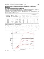
A
physical solvent process
is
shown
in
Figure
7-6.
The
sour
gas
con-
tacts
the
solvent
using counter-current
flow in the
absorber. Rich solvent
from
the
absorber bottom
is
flashed
in
stages
to a
pressure near atmos-
170
Design
of
GAS-HANDLING
Systems
and
Facilities
pherie.
This causes
the
acid-gas partial pressures
to
decrease;
the
acid
gases evolve
to the
vapor phase
and are
removed.
The
regenerated
sol-
vent
is
then pumped back
to the
absorber.
The
example
in
Figure
7-6 is a
simple
one in
that
flashing is
sufficient
to
regenerate
the
solvent. Some solvents require
a
stripping
column
just
prior
to the
circulation pump.
Most
physical solvent processes
are
proprietary
and are
licensed
by the
company
that developed
the
process.
Fluor
Solvent
Process®
This process uses propylene carbonate
as a
physical solvent
to
remove
CO
2
and
H
2
S.
Propylene carbonate
also
removes
C
2
+
hydrocarbons,
COS,
SO
2
,
CS
2
,
and
H
2
O
from
the
natural
gas
stream. Thus,
in one
step
the
natural
gas can be
sweetened
and
dehydrated
to
pipeline quality.
In
general, this process
is
used
for
bulk
removal
of
CO
2
and is not
used
to
treat
to
less than
3%
CO
2
,
as may be
required
for
pipeline
quality
gas,
The
system requires special design features, larger absorbers,
and
higher
circulation rates
to
obtain pipeline quality
and
usually
is not
economical-
ly
applicable
for
these outlet requirements.
Figure 7-6. Physical solvent process.
Acid
Gas
Treating
171
Propylene
carbonate
has the
following characteristics, which
make
it
suitable
as a
solvent
for
acid
gas
treating:
1.
High
degree
of
solubility
for
CO
2
and
other gases.
2.
Low
heat
of
solution
for
CO
2
.
3.
Low
vapor pressure
at
operating temperature.
4. Low
solubility
for
light hydrocarbons
(C
l5
C
2
).
5.
Chemically nonreactive toward
all
natural
gas
components.
6. Low
viscosity.
7.
Noncorrosive
toward common metals.
These
characteristics combine
to
yield
a
system that
has low
heat
and
pumping
requirements,
is
relatively
noncorrosive,
and
suffers
only mini-
mal
solvent
losses
(less than
1
Ib/MMscf).
Solvent
temperatures below ambient
are
usually used
to
increase
the
solubility
of
acid
gas
components
and
therefore decrease circulation rates.
Sulfinol®
Process
Licensed
by
Shell
the
Sulfinol®
process combines
the
properties
of a
physical
and a
chemical solvent.
The
Sulfinol®
solution consists
of a
mixture
of
sulfolane
(tetrahydrothiophene
1-1
dioxide), which
is a
physi-
cal
solvent,
diisopropanolamine
(DIPA),
and
water.
DIPA
is a
chemical
solvent that
was
discussed under
the
amines.
The
physical solvent sulfolane provides
the
system with bulk removal
capacity.
Sulfolane
is an
excellent solvent
of
sulfur
compounds such
as
H
2
S,
COS,
and
CS
2
.
Aromatic
and
heavy hydrocarbons
and
CO
2
are
sol-
uble
in
sulfolane
to a
lesser
degree.
The
relative amounts
of
DIPA
and
sulfolane
are
adjusted
for
each
gas
stream
to
custom
fit
each application.
Sulfinol®
is
usually used
for
streams with
an
H
2
S
to
CO
2
ratio
greater
than
1:1
or
where
it is not
necessary
to
remove
the
CO
2
to the
same lev-
els as is
required
for
H
2
S
removal.
The
physical solvent allows much
greater solution loadings
of
acid
gas
than
for
pure
amine-based
systems.
Typically,
a
Sulfinol®
solution
of 40%
sulfolane,
40%
DIPA
and 20%
water
can
remove
1.5
moles
of
acid
gas per
mole
of
Sulfinol®
solution.
The
chemical solvent DIPA acts
as
secondary treatment
to
remove
H
2
S
and
CO
2
.
The
DIPA allows pipeline quality residual levels
of
acid
gas to
be
achieved easily.
A
stripper
is
required
to
reverse
the
reactions
of the
DIPA
with
CO
2
and
H
2
S.
This adds
to the
cost
and
complexity
of the
sys-
172
Design
of
GAS-HANDLING
Systems
and
Facilities
tern
compared
to
other physical solvents,
but the
heat requirements
are
much
lower than
for
amine
systems,
A
reclaimer
is
also required
to
remove
oxazolidones
produced
in a
side
reaction
of
DIPA
and
CO
2
.
Selexol®
Process
Developed
by
Allied Chemical Company, this process
is
selective
toward
removing
sulfur
compounds. Levels
of
CO
2
can be
reduced
by
approximately 85%. This process
may be
used economically when there
are
high acid-gas partial pressures
and the
absence
of
heavy ends
in the
gas,
but it
will
not
normally meet pipeline
gas
requirements. This process
also removes water
to
less than
1
Ib/MMscf.
DIPA
can be
added
to the
solution
to
remove
CO
2
down
to
pipeline specifications. This system
then
functions
much like
the
Sulfinol®
process discussed earlier.
The
addition
of
DIPA will increase
the
stripper heat duty; however,
this
duty
is
relatively
low.
Rectisol®
Process
The
German Lurgi Company
and
Linde
A. G.
developed
the
Rectisol®
process
to use
methanol
to
sweeten natural gas.
Due to the
high vapor
pressure
of
methanol this process
is
usually
operated
at
temperatures
of
-30 to
~100°F.
It has
been applied
to the
purification
of gas for LNG
plants
and in
coal gasification plants,
but is not
used commonly
to
treat
natural
gas
streams.
Direct
Conversion
of
H
2
S
to
Sulfur
The
chemical
and
solvent processes previously discussed remove acid
gases
from
the gas
stream
but
result
in a
release
of
H
2
S
and
CO
2
when
the
solvent
is
regenerated.
The
release
of
H
2
S
to the
atmosphere
may be
limited
by
environmental regulations.
The
acid gases
could
be
routed
to
an
incinerator
or
flare, which
would
convert
the
H
2
S
to
SO
2
.
The
allow-
able rate
of
SO
2
release
to the
atmosphere
may
also
be
limited
by
envi-
ronmental
regulations.
For
example, currently
the
Texas
Air
Control
Board generally limits
H
2
S
emissions
to 4
Ib/hr
(17.5 tons/year)
and
SO
2
emissions
to 25
tons/year. There
are
many specific restrictions
on
these
limits,
and the
allowable limits
are
revised periodically.
In any
case,
environmental
regulations severely restrict
the
amount
of
H
2
S
that
can be
vented
or
flared
in the
regeneration cycle.
Acid
Gas
Treating
173
Direct
conversion
processes
use
chemical reactions
to
oxidize
H
2
S
and
produce
elemental
sulfur.
These processes
are
generally based either
on
the
reaction
of
H
2
S
and
O
2
or
H
2
S
and
SO
2
.
Both reactions yield
water
and
elemental
sulfur.
These processes
are
licensed
and
involve special-
ized
catalysts
and/or
solvents.
A
direct conversion process
can be
used
directly
on the
produced
gas
stream. Where large
flow
rates
are
encoun-
tered,
it is
more common
to
contact
the
produced
gas
stream
with
a
chemical
or
physical solvent
and use a
direct conversion process
on the
acid
gas
liberated
in the
regeneration
step.
Claus®
Process
This process
is
used
to
treat
gas
streams containing high concentra-
tions
of
H2S.
The
chemistry
of the
units involves partial oxidation
of
hydrogen
sulfide
to
sulfur
dioxide
and the
catalyticaily
promoted
reac-
tion
of
H
2
S
and
SO
2
to
produce elemental
sulfur.
The
reactions
are
staged
and
are as
follows:
Figure
7-7
shows
a
simplified process
flow
diagram
of the
Claus®
process.
The first
stage
of the
process converts
H
2
S
to
sulfur
dioxide
and
Figure
7-7.
Two-stage
Claus
process
plant.
174
Design
of
GAS-HANDLING
Systems
and
Facilities
to
sulfur
by
burning
the
acid-gas stream
with
air in the
reaction
furnace,
This
stage provides
SO
2
for the
next catalytic phase
of the
reaction.
Mul-
tiple
catalytic stages
are
provided
to
achieve
a
more complete conversion
of
the
H
2
S.
Condensors
are
provided
after
each stage
to
condense
the
sul-
fur
vapor
and
separate
it
from
the
main stream. Conversion
efficiencies
of
94-95%
can be
attained with
two
catalytic stages, while
up to 97%
conversion
can be
attained with three catalytic stages.
The
effluent
gas is
incinerated
or
sent
to
another treating
unit
for
"tail-gas treating" before
it
is
exhausted
to
atmosphere.
There
are
many processes used
in
tail-gas treating.
The
Sulfreen®
and
the
Cold
Bed
Absorption®
(CBA)
processes
use two
parallel reactors
in a
cycle,
where
one
reactor operates below
the
sulfur
dew
point
to
absorb
the
sulfur
while
the
second
is
regenerated with heat
to
recover molten
sulfur.
Even
though
sulfur
recoveries with
the
additional reactors
are
nor-
mally
99-99.5%
of the
inlet stream
to the
Claus
unit,
incineration
of the
outlet
gas may
still
be
required.
The
SCOTT® process uses
an
arnine
to
remove
the
H
2
S.
The
acid
gas
off
the
amine
still
is
recycled back
to the
Claus
plant.
Other types
of
processes oxidize
the
sulfur
compounds
to
SO
2
and
then convert
the
SO
2
to
a
secondary product such
as
ammonium
thiosulfate,
a
fertilizer. These
plants
can
remove more
than
99.5%
of the
sulfur
in the
inlet stream
to
the
Claus plant
and may
eliminate
the
need
for
incineration. Costs
of
achieving
this removal
are
high.
LOCAT®
Process
The
LOCAT®
process
is a
liquid phase oxidation process based
on a
dilute
solution
of a
proprietary, organically chelated iron
in
water that
converts
the
hydrogen sulfide
to
water
and
elemental
sulfur.
The
process
is
not
reactive
to
CO
2
.
A
small portion
of the
chelating agent degrades
in
some side reactions
and is
lost with
the
precipitated
sulfur.
Normally, sul-
fur
is
separated
by
gravity,
centrifuging,
or
melting.
Figure
7-8
represents
a
process
flow
diagram
of the
LOCAT® process.
The
H
2
S
is
contacted with
the
reagent
in an
absorber;
it
reacts with
the
dissolved
iron
to
form elemental
sulfur.
The
reactions involved
are the
following:
Acid
Gas
Treating
175
Figure
7-8. LOCAT® process.
The
iron,
now in a
reduced ferrous
form,
is not
consumed; instead,
it is
continuously regenerated
by
bubbling
air
through
the
solution.
The
sulfur
precipitates
out of the
solution
and is
removed
from
the
reactor
with
a
portion
of the
reagent.
The
sulfur
slurry
is
pumped
to a
melter
requiring
a
small
amount
of
heat
and
then
to a
sulfur
separator where
the
reagent
in
the
vapor phase
is
recovered, condensed,
and
recycled back
to the
reactor.
LOCAT®
units
can be
used
for
tail-gas clean-up from chemical
or
physical solvent processes. They
can
also
be
used directly
as a gas
sweet-
ening
unit
by
separating
the
absdrber/oxidizer
into
two
vessels.
The
regenerated solution
is
pumped
to a
high-pressure absorber
to
contact
the
gas.
A
light slurry
of rich
solution comes
off the
bottom
of the
absorber
and
flows to an
atmospheric oxidizer tank where
it is
regenerated.
A
dense slurry
is
pumped
off the
base
of the
oxidizer
to the
melter
and
sul-
fur
separator.
Stretford®
Process
An
example
of a
process using
O
2
to
oxidize
H
2
S
is the
Stretford®
process,
which
is
licensed
by the
British
Gas
Corporation.
In
this
process
the
gas
stream
is
washed with
an
aqueous solution
of
sodium carbonate,
sodium
vanadate,
and
anthraquinone
disulfonic acid. Figure
7-9
shows
a
simplified
process diagram
of the
process.
176
Design
of
GAS-HANDLING
Systems
and
Facilities
Figure
7-9.
Strefford®
process.
Oxidized solution
is
delivered
from
the
pumping tank
to the top of the
absorber tower, where
it
contacts
the gas
stream
in a
counter-current
flow.
The
reduced solution flows
from
the
contactor
to the
solution
flash
drum.
Hydrocarbon gases that have been dissolved
in the
solution
are
flashed
and the
solution
flows to the
base
of the
oxidizer vessel.
Air is
blown
into
the
oxidizer,
and the
solution,
now
re-oxidized,
flows to the
pumping
tank.
The
sulfur
is
carried
to the top of the
oxidizer
by a
froth
created
by the
aeration
of the
solution
and
passes
into
the
thickener.
The
function
of the
thickener
is to
increase
the
weight percent
of
sulfur,
which
is
pumped
to
one of the
alternate
sulfur
recovery methods.
IFP
Process
The
Institute
Francais
du
Petrole
has
developed
a
process
for
reacting
H2S
with
SO
2
to
produce water
and
sulfur.
The
overall reaction
is
2H
2
S
+
862
-»
2H2O
+ 3S.
Figure 7-10
is a
simplified diagram
of the
process.
This process involves mixing
the
H
2
S
and
SO
2
gases
and
then
contacting
them
with
a
liquid catalyst
in a
packed tower. Elemental
sulfur
is
recov-
ered
in the
bottom
of the
tower.
A
portion
of
this must
be
burned
to
pro-
duce
the SO2
required
to
remove
the
H
2
S.
The
most important variable
is
the
ratio
of
H
2
S
to
SO
2
in the
feed. This
is
controlled
by
analyzer equip-
ment
to
maintain
the
system performance.
Sulfa-Check®
Sulfa-Check®
process
uses sodium nitrite
(NaNO
2
)
in
aqueous solu-
tion
to
oxidize
H
2
S
to
sulfur.
This process
was
developed
and
patented
by
NL
Treating Chemicals
and is now a
product
of
Exxon Energy
Chem-
Acid
Gas
Treating
177
Figure
7-10.
IFF
process.
icals.
It
will generate
NO
X
in
presence
of
CO
2
and
O
2
.
Therefore, local
air
quality emission standard should
be
consulted. This process
is
most
suited
for
small
gas
streams, generally
0.1
to 10
MMscfd
and
containing
100ppmto<
1%H
2
S.
Sulfa-Check®
gas
sweetening process
is
generally carried
out in a
con-
tact
tower.
The
sour
gas flows
into
the
bottom
of the
tower
and
through
a
sparging
system
to
disperse
the gas
throughout
the
chemical solution.
The
maximum linear
gas
velocity should
be <
0.12
ft/sec.
The
sweetened
gas
exits
the
contact tower
at the top and
goes
to a
gas/liquid separator
to
catch
any
liquids that
may be
carried over.
An
inverted
U
with
a
syphon
breaker
on top
should
be
designed into
the gas
inlet line
to
prevent
the
liquid from
being
siphoned
back. When
the
chemical
is
spent,
the
system
is
shut down
to
remove
the
spent chemical
and
recharged
with
a
fresh
solution
to
resume
the
operation.
Sulfide
Scavengers
Sour
gas
sweetening
may
also
be
carried
out
continuously
in the flow-
line
by
continuous injection
of
H^S
scavengers, such
as
amine-aldehyde
condensates. Contact time between
the
scavenger
and the
sour
gas is the
most critical factor
in the
design
of the
scavenger treatment process.
Contact times shorter than
30 sec can be
accommodated with faster
reacting
and
higher volatility formulations.
The
arnine-aldehyde
conden-
sates process
is
best suited
for wet gas
streams
of
0.5-15
MMscfd
con-
taining
less
than
100
ppm
H
2
S.
1
78
Design
of
GAS-HANDLING
Systems
and
Facilities
The
advantages
of
amine-aldehyde
condensates
are
water
(or
oil)
solu-
ble
reaction products, lower operating temperatures,
low
corrosiveness
to
steel,
and no
reactivity with hydrocarbons,
Distillation
The
Ryan-Holmes
distillation process uses cryogenic distillation
to
remove acid gases
from
a gas
stream. This process
is
applied
to
remove
CO
2
for LPG
separation
or
where
it is
desired
to
produce
CO
2
at
high
pressure
for
reservoir injection. This complicated process
is
beyond
the
scope
of
this book.
Gas
Permeation
Gas
permeation
is
based
on the
mass transfer principles
of gas
diffusion
through
a
permeable membrane.
In its
most basic
form,
a
membrane sepa-
ration system consists
of a
vessel divided
by a
single
flat
membrane into
a
high-
and a
low-pressure section.
Feed
entering
the
high-pressure side
selectively
loses
the
fast-permeating components
to the
low-pressure side.
Flat plate designs
are not
used commercially,
as
they
do not
have enough
surface
area.
In the
hollow-fiber design,
the
separation modules contain
anywhere
from
10,000
to
100,000
capillaries, each less than
1 mm
diame-
ter,
bound
to a
tube sheet surrounded
by a
metal shell. Feed
gas is
intro-
duced into either
the
shell
or the
tube side. Where
gas
permeability rates
of
the
components
are
close,
or
where high product purity
is
required,
the
membrane
modules
can be
arranged
in
series
or
streams
recycled.
The
driving force
for the
separation
is
differential pressure.
CO
2
tends
to
diffuse
quickly through membranes
and
thus
can be
removed
from
the
bulk
gas
stream.
The low
pressure side
of the
membrane that
is rich in
CO
2
is
normally operated
at
10
to 20% of the
feed pressure.
It
is
difficult
to
remove
H
2
S
to
pipeline quality with
a
membrane sys-
tem.
Membrane systems have effectively been used
as a
first
step
to
remove
the
CO
2
and
most
of the
H
2
S.
An
iron sponge
or
other
H
2
S
treat-
ing
process
is
then used
to
remove
the
remainder
of the
H
2
S.
Membranes will also remove some
of the
water vapor. Depending
upon
the
stream properties,
a
membrane designed
to
treat
CO
2
to
pipeline
specifications
may
also
reduce water vapor
to
less
than
7
Ib/MMscf.
Often,
however,
it is
necessary
to
dehydrate
the gas
downstream
of the
membrane
to
attain
final
pipeline water vapor requirements.
Acid
Gas
Treating
1
79
Membranes
are a
relatively
new
technology. They
are an
attractive
economic alternative
for
treating
CO
2
from
small streams
(up to 10
MMscfd).
With
time they
may
become common
on
even larger
streams,
PROCISS
SELECTION
Each
of the
previous treating processes
has
advantages relative
to the
others
for
certain applications; therefore,
in
selection
of the
appropriate
process,
the
following
facts
should
be
considered:
1.
The
type
of
acid contaminants present
in the gas
stream.
2. The
concentrations
of
each contaminant
and
degree
of
removal
desired.
3. The
volume
of gas to be
treated
and
temperature
and
pressure
at
which
the gas is
available.
4. The
feasibility
of
recovering
sulfur.
5. The
desirability
of
selectively removing
one or
more
of the
contami-
nants without removing
the
others.
6.
The
presence
and
amount
of
heavy hydrocarbons
and
aromati.cs
in
the
gas,
Figures
7-11
to
7-14
can be
used
as
screening tools
to
make
an
initial
selection
of
potential
process
choices.
These
graphs
are not
meant
to
sup-
plant engineering judgment.
New
processes
are
continuously being
developed. Modifications
to
existing proprietary products will
change
their
range
of
applicability
and
relative cost.
The
graphs
do
enable
a
first
choice
of
several potential candidates that could
be
investigated
to
deter-
mine which
is the
most
economical
for a
given
set of
conditions.
To
select
a
process, determine
flow
rate, temperature,
pressure,
con-
centration
of the
acid gases
in the
inlet gas,
and
allowed concentration
of
acid gases
in the
outlet stream. With this information, calculate
the
par-
tial
pressure
of the
acid
gas
components.
where
PPj
=
partial pressure
of
component
i,
psia
P
t
=
systems pressure, psia
Xj
=
mole fraction
of
component
i
1
SO
Df>.\i&n
ofGAfi-HANDUNCi
Systems
and
Facilities
Figure
7-11.
H
2
S
removal,
no
CQ&
Next,
determine
if one of the
four
following situations
is
required
and
use
the
appropriate guide:
Removal
of
H
2
S
with
no
CO
2
present (Figure
7-11)
Removal
of
H
2
S
and
CO
2
(Figure
7-12)
Removal
of
CO
2
with
no
H
2
S
present (Figure
7-13)
Selective removal
of
H
2
S
with
CO
2
present (Figure
7-14)
DESIGN
PROCEDURES
FOR
IRON-SPONGE UNITS
The
iron-sponge process generally uses
a
single vessel
to
contain
the
hydrated
ferric oxide wood shavings.
A
drawing
of an
iron-sponge unit
showing
typical provisions
for
internal
and
external design requirements
was
presented
in
Figure
7-3.
The
inlet
gas
line should have taps
for gas
sampling, temperature
mea-
surement,
pressure measurement,
and for an
injection nozzle
for
Acid
Gas
Treating
181
Figure
7-12.
Removal
of
H
2
S
and
C€>2.
methanol,
water,
or
inhibitors.
The gas is
carried into
the top
section
of
the
vessel
in a
distributor
and
discharged upward. This causes
the gas to
reverse
flow
downward
and
provides
for
more
uniform
flow
through
the
bed, minimizing
the
potential
for
channeling.
Supporting
the
hydrated
ferric
oxide chips
is a
combination
of a
perfo-
rated,
heavy
metal
support
plate
and a
coarse
support
packing
material.
This material
may
consist
of
scrap pipe thread protectors
and
2-3-in.
sec-
tions
of
small diameter
pipe.
This provides support
for the
bed, while
offering
some protection against detrimental pressure surges.
Gas
exits
the
vessel
at the
bottom through
the
vessel sidewall. This
arrangement
minimizes
entrainment
of fines.
Additionally,
a
cone strain-
er
should
be
included
in the
exit
line.
This line should also have
a
pres-
sure
tap and
sample test tap.
The
vessel
is
generally constructed
of
carbon steel that
has
been heat
treated. Control
of
metal hardness
is
required because
of the
potential
of
sulfide-stress
cracking.
The
iron-sponge vessel
is
either internally coated
or
clad
with
stainless steel.
182
Design
of
GAS-HANDLING
Systems
and
Facilities
Figure
7-13.
CO2
removal,
no
h^S.
The
superficial
gas
velocity (that
is, gas flow
rate divided
by
vessel
cross-sectional area) through
the
iron-sponge
bed is
normally limited
to a
maximum
of 10
ft/min
at
actual
flow
conditions
to
promote
proper
con-
tact with
the bed and to
guard against excessive pressure drop. Thus,
the
vessel
minimum diameter
is
given
by:
where
d
min
=
minimum required vessel diameter,
in.
Q
g
= gas flow
rate, MMscfd
T
=
operating temperature,
°R
Z =
compressibility factor
P =
operating pressure,
psia
A
maximum rate
of
deposition
of 15
grains
of
H
2
S/min/ft
2
of bed
cross-sectional area
is
also recommended
to
allow
for the
dissipation
of
Acid
Gas
Treating
183
Figure 7-14. Selective removal
of
H
2
S
in
presence
of
CO
2
.
the
heat
of
reaction. This requirement also establishes
a
minimum
required
diameter,
which
is
given
by:
where
d
min
=
minimum required vessel diameter,
in.
Q
g
= gas flow
rate, MMscfd
MF
=
mole fraction
of
H
2
S
The
larger
of the
diameters calculated
by
Equation
7-18
or
7-19
will
set
the
minimum vessel diameter.
Any
choice
of
diameter equal
to or
larger
than
this diameter will
be an
acceptable choice.
At
very
low
superficial
gas
velocities
(less
than
2
ft/min)
channeling
of
the gas
through
the bed may
occur. Thus,
it is
preferred
to
limit
the
vessel
diameter
to:
184
Design
of
GAS-HANDLING
Systems
and
Facilities
where
d
max
=
maximum
recommended vessel diameter,
in.
A
contact time
of 60
seconds
is
considered
a
minimum
in
choosing
a bed
volume.
A
larger volume
may be
considered,
as it
will
extend
the bed
liie
and
thus extend
the
cycle time between
bed
change outs. Assuming
a
minimum
contact time
of 60
seconds,
any
combination
of
vessel diame-
ter
and bed
height
that
satisfies
the
following
is
acceptable:
j.
where
d =
vessel diameter,
in.
H
= bed
height,
ft
In
selecting
acceptable combinations,
the bed
height
should
be at
least
10
ft for
H
2
S
removal
and 20 ft for
mercaptan
removal. This height
will
produce
sufficient
pressure drop
to
assure proper
flow
distribution over
the
entire
cross-section. Thus,
the
correct vessel size will
be one
that
has
a bed
height
of at
least
10
ft (20 ft if
mercaptans
must
be
removed)
and a
vessel diameter between
d
min
and
d
max
.
Iron
sponge
is
normally sold
in the
U.S.
by the
bushel.
The
volume
in
bushels
can be
determined
from
the
following equation once
the bed
dimensions
of
diameter
and
height
are
known:
where
Bu
=
volume, bushels
The
amount
of
iron oxide that
is
impregnated
on the
wood chips
is
nor-
mally
specified
in
units
of
pounds
of
iron oxide
(Fe
2
O
3
)
per
bushel.
Common grades
are 9, 15 or 20
Ib
Fe2O
3
/bushel.
Bed
life
for the
iron sponge between change outs
is
determined
from:
where
t
c
=
cycle
time, days
Fe =
iron-sponge
content,
Ib
Fe2O3/bushel
e =
efficiency
(0.65
to
0.8)
MF =
mole
fraction
H
2
S
Acid
Gas
Treating
185
The
iron-sponge
material
is
normally specified
to
have
a
size distribution
with
0%
retained
on
16
mesh,
80%
between
30 and 60
mesh,
and
100%
retained
on 325
mesh.
It is
purchased with
a
moisture content
of 20% by
weight
and
buffering
to
meet
a flood pH of
10.
Because
it is
necessary
to
maintain
a
moist alkaline condition, provisions should
be
included
in the
design
to add
water
and
caustic.
DESIGN
PROCEDURES
FOR
AMINE
SYSTEMS
The
types
of
equipment
and the
methods
for
designing
the
equipment
are
similar
for
both
MEA and
DBA
systems.
For
other amine systems
such
as
SNPA-DEA, Fluor
Econamine
(DGA),
and
Shell
ADIP
(DIPA)
the
licensee
should
be
contacted
for
detailed design information.
Amine
Absorber
Amine
absorbers
use
counter-current
flow
through
a
trayed
or
packed
tower
to
provide intimate mixing between
the
amine solution
and
the
sour
gas. Typically, small diameter towers
use
stainless
steel
packing,
while
larger towers
use
stainless steel trays.
For
systems using
the
rec-
ommended solution concentrations
and
loadings,
a
tower with
20 to 24
actual
trays
is
normal. Variations
in
solution concentrations
and
loadings
may
require
further
investigation
to
determine
the
number
of
trays.
In
a
trayed absorber
the
amine falls
from
one
tray
to the one
below
in
the
same manner
as the
liquid
in a
condensate
stabilizer (Chapter
6,
Fig-
ure
6-4).
It
flows
across
the
tray
and
over
a
weir before
flowing
into
the
next
downcomer.
The gas
bubbles
up
through
the
liquid
and
creates
a
froth
that must
be
separated
from
the gas
before
it
reaches
the
underside
of
the
next
tray.
For
preliminary design,
a
tray spacing
of 24 in. and a
minimum diameter
capable
of
separating
150 to 200
micron
droplets
(using
the
equations developed
in
Volume
1 for gas
capacity
of a
vertical
separator)
can be
assumed.
The
size
of
packed towers must
be
obtained
from
manufacturer's published literature.
Commonly,
amine absorbers include
an
integral
gas
scrubber section
in
the
bottom
of the
tower. This scrubber would
be the
same diameter
as
required
for the
tower.
The gas
entering
the
tower would have
to
pass
through
a
mist
eliminator
and
then
a
chimney tray.
The
purpose
of
this
scrubber
is to
remove entrained water
and
hydrocarbon
liquids
from
the
gas to
protect
the
amine solution
from
contamination.