ARNOLD, K. (1999). Design of Gas-Handling Systems and Facilities (2nd ed.) Episode 2 Part 4 pdf
Bạn đang xem bản rút gọn của tài liệu. Xem và tải ngay bản đầy đủ của tài liệu tại đây (1.03 MB, 25 trang )
Reciprocating
Compressors
311
Single-acting
cylinder, crank
end
Double-acting
cylinder
where
RL
C
=
rod
load
in
compression,
ib
RL,
= rod
load
in
tension,
Ib
ap
=
cross-sectional area
of
piston,
in.
2
P
d
=
discharge pressure, psia
P
s
=
suction pressure, psia
P
u
=
pressure
in
unloaded area, psia
a
r
=
cross-sectional
area
of
rod,
in,
2
The
calculations shown above provide
the gas
load imposed
on the rod
(and
crosshead
bushing)
by the
compressor
cylinder
piston.
To
provide
a
reasonable
crosshead
pin
bushing
life,
the rod
loading
at the
crosshead
bushing must change
from
compression
to
tension
during
each
revolu-
tion.
This
is
commonly referred
to as
"rod
reversal"
and
allows
oil to
lubricate
and
cool
one
side
of the
bushing while load
is
being applied
to
the
other side
of the
bushing.
A
single-acting,
head
end
cylinder will
not
have load reversal
if
suc-
tion
pressure
is
applied
to the
crank
end.
Similarly,
if
discharge pressure
is
applied
to the
head
end of a
single-acting, crank
end
cylinder, load
reversal will
not
occur.
In
addition
to the gas
load,
the rod and
crosshead
pin
bushing
is
sub-
ject
to the
inertia
forces
created
by the
acceleration
and
deceleration
of
the
compressor reciprocating mass.
The
inertia load
is a
direct
function
of
crank radius,
the
reciprocating weight,
and
speed squared.
The
total
load
imposed
on the
crosshead
pin and
bushing
is the sum of the gas
load
and
the
inertia load
and is
referred
to as the
"combined
rod
load."
The
combined
rod
load should
be
checked anytime
the gas
loads
are
approaching
the
maximum rating
of the
compressor
frame
or
anytime
rod
reversal
is
marginal
or
questionable.
312
Design
of
GAS-HANDLING
Systems
and
Facilities
COOLING
AND
LUBRICATION
SYSTEMS
Compressor
Cylinder Cooling
Traditional compressor cylinder designs require cooling water jackets
to
promote uniform distribution
of
heat created
by gas
compression
and
friction.
Some
of the
perceived advantages
of
water-cooled cylinders
are
reduced suction
gas
preheat, better cylinder lubrication, prolonged parts
life,
and
reduced maintenance.
Operating experience during
the
last
30
years
has
proven that
com-
pressor cylinders designed without cooling water jackts (non-cooled)
can
successfully
operate
in
most natural
gas
compession applications.
Some
of
the
perceived advantgaes
of
non-cooled cylinders
are
simplified
cylin-
der
designs that reduce cost
and
improve
efficiency,
reduced
initial
sys-
tem
costs
due to
reductions
in the
cooling water system, improved
valve
accessibility,
and
reduced weight.
Many
manufacturers, users,
and
compressor applications still require
that
compressor cylinders
be
supplied with liquid-cooled cylinders.
Fig-
ure
11-21
includes schematics
of
several types
of
liquid coolant systems.
In
static systems,
the
cooling jackets
are
normally
filled
with
a
glycol
and
water mixture
to
provide
for
uniform
heat distribution
within
the
cylinder. This
system
may be
used where
the AT of the gas is
less than
150°F
and
discharge
gas
temperature
is
less
than 190°F.
Thermal siphons
use the
density differences between
the hot and the
cold coolants
to
establish
flow.
This system
may be
used where
the AT of
the
gas is
less than
150°F
and
discharge
gas
temperature
is
less
than
210°F.
Forced coolant systems using
a
mixture
of
glycol
and
water
are the
most common
for
natural
gas
compressors. Normally,
the
compressor
cylinder
cooling system
and
compressor
frame
lube
oil
cooling system
is
combined.
A
single pump
is
used
to
circulate
the
coolant through
the
cylinders
and
the
lube
oil
heat exchanger
and
then
to an
aerial cooler
where
the
heat
is
dissipated.
When forced coolant systems
are
used,
care
must
be
taken
to
provide
the
coolant
at the
proper temperature.
If the
cylinder
is too
cool, liquids
could condense
from
the
suction
gas
stream. Thus,
it is
desirable
to
keep
the
coolant temperature
10°F
higher than that
of the
suction
gas.
If the
cylinder
is too
hot,
gas
throughput capacity
is
lost
due to the gas
heating
and
expanding. Therefore,
it is
desirable
to
limit
the
coolant
temperature
to
less
than
30°F
above that
of the
suction
gas.
Reciprocating
Compressors
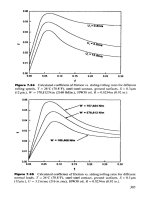
313
Figure
11-21.
Cylinder cooling
systems.
(Reprinted
with
permission
from
API,
Sid.
618,
3rd
id.,
Feb.
1986.)
Frame
Lubrication
System
The frame
lubrication system circulates
oil to the
frame
bearings,
con-
necting
rod
bearings, crosshead shoes,
and can
also supply
oil to the
packing
and
cylinder lubrication system. Splash lubrication systems
are
314
Design
of
GAS-HANDLING
Systems
and
Facilities
the
least expensive
and are
used
in
small
air
compressors. Forced-feed
systems
are
used
for
almost
all
oilfield
gas
compression applications.
Figure
11-22
shows
a
splash
lubrication
system
where
an oil
ring
rides
loosely
and
freely
on the
rotating
shaft,
dipping into
the oil
sump
as it
rotates.
The
ring rotates because
of its
contact with
the
shaft,
but at a
slower
speed.
The oil
adheres
to the ring
until
it
reaches
the top of the
journal
when
it
flows
onto
the
shaft.
Figure
11-22.
Splash
lubrication
system
(oil
stinger).
Reciprocating
Compressors
315
lo
a
forced-feed lubrication system,
a
pump circulates lubricating
oil
through
a
cooler
and
filter
to a
distribution system that directs
the oil to all
the
bearings
and
crosshead
shoes.
Figure
11
-23 is a
schematic
of a
typical
system.
The
details
of any one
system will vary greatly. Major components
and
considerations
of a
forced feed lubrication system
are as
follows:
*
Main
oil
pump
-
Driven from crankshaft.
-
Should
be
sized
to
deliver
110%
of the
maximum anticipated
flow
rate.
*
Auxiliary pump
-
Backup
for the
main
oil
pump.
-
Electric
motor
driven.
Figure
11-23.
Forced-feed
lubrication
system.
316
Design
of
GAS-HANDLING
Systems
and
Facilities
-
Should start automatically when supply pressure falls below
a
cer-
tain
level.
•
Pre-lube
pump
-
Manual
or
automatic.
-
Prevents running bearings
dry at
start.
•
Oil
cooler
-
Keeps
oil
temperature below
165°F.
-
Can use
shell-and-tube
exchanger with jacket cooling water
or
air-
cooled
exchanger.
-
Sized
for
110%
of the
maximum anticipated duty.
• Oil filter
-
Dual,
full
flow,
with isolation valves arranged
so
switching
can
occur without causing
a
low-pressure shutdown.
-
Size should
be
determined
by
vendor;
in
lieu
of
other information
use
API
618
requirements.
»Overhead
day
tank
-
Sized
to
handle
one
month
of oil
consumption.
-
Should
be
equipped with
a
level
indicator,
•
Piping
-
Stainless steel
downstream
of
filters.
-
No
galvanizing.
-
No
socket welding
or
other pockets that
can
accumulate dirt down-
stream
of
filter.
-
Carbon steel lines should
be
pickled, passivated,
and
coated
with
rust
inhibitor.
-
Lube
oil
system
from pump discharge
to the
distribution system
should
be
flushed with
lube
oil at
160°F-180°R
Oil
should
flow
across
a 200
mesh screen
and
flushing should
cease
when
no
more
dirt
or
grit
is
found
on the
screen.
Packing/cylinder
lubrication
can be
provided
from
a
forced feed
com-
pressor lube
oil
system.
For
very cold installations, immersion
heaters
and
special
lube
oils
must
be
considered.
If the
lube
oil
temperature
gets
too
cold,
the oil
becomes
too
viscous
and
does
not flow and
lubricate
properly.
Cylinder/Packing
Lubrication
System
The
flow
required
to
lubricate
the
packing
and
cylinders
is
quite small,
and
the
pressure
necessary
to
inject
the
lubricant
at
these
locations
is
quite
high. Therefore, small plunger pump (force-feed lubricators)
sys-
Reciprocating
Compressors
317
terns
are
used.
The
force-feed lubricators
are
usually
driven
by the
com-
pressor
crankshaft,
The two
basic types
of
cylinder lubrication systems
are the
pump-to-
point
system
and the
divider-block system.
The
pump-to-point system
provides each lubrication point with
its own
lubricator
pump.
Thus,
if the
compressor cylinders
and
packing require
six
lubrication points,
the
lubri-
cator
box
would
be
supplied
with
six cam
driven pumps.
The
divider-
block system uses
one or
more lubricator pumps
to
supply
a
divider block,
which
then distributes
the flow to
each
of the
lubrication points.
The
two
systems
are
sometimes combined such
that
each stage
of
compression
is
provided with
its own
pump
and a
divider block
to
distribute
the flow
between
the
cylinders
and
packing
of
that particular
stage.
Oil is
supplied
to
this system
from
the
frame
lube
oil
system
or
from
an
overhead tank. This
oil
comes
in
contact
with
and
thus contaminates
the
gas
being
compressed.
Gas/oil compatibility should
be
checked.
PIPE
SIZING
CONSIDERATIONS
Because
of the
reciprocating action
of the
piston, care must
be
exer-
cised
to
size
the
piping
to
minimize acoustical pulsations
and
mechanical
vibrations.
As a
rule
of
thumb, suction
and
discharge
lines
should
be
sized
for a
maximum actual velocity
of 30
ft/sec
(1,800
ft/min)
to 42
ft/sec
(2,500
ft/min).
Volume
1
contains
the
necessary formulas
for
deter-
mining
pressure drop
and
velocity
in gas
piping.
Analog
or
digital simulators
can be
used
to
establish
the
pulsation per-
formance
of any
compressor
piping system
in
detail.
API
618
Section
3.9.2 provides guidelines
for
piping
pulsation
and
vibration control based
on
compressor discharge pressure
and
horsepower.
In
practice, many
operators
do not
"analog"
compressors
of
1,000 horsepower
or
lower,
but
rather
rely
on
extrapolations
from
proven designs.
For
larger horsepower
sizes
or
where unusual conditions (e.g., unloading
and
loading cylinders)
exist,
an
analog
is
recommended.
For
smaller, high-speed compressors
the
piping sizing rules
of
thumb
discussed above,
in
conjunction with pulsation
bottles
sized
from
Figure
11
-24, should
be
sufficient
for
individual
field
compressors. These rules
of
thumb
can
also
be
used
for
preliminary sizing
of
piping
and
bottles
in
preparation
for an
analog
study.
To
minimize pipe vibrations
it is
necessary
to
design pipe runs
so
that
the
"acoustic
length"
of the
pipe
run
does
not
create
a
standing wave
that
318
Design
of
GAS-HANDLING
Systems
and
Facilities
Figure
11
-24.
Pulsation
bottle
sizing
chart
(approximation).
(Reprinted
wilh
permission
from
GPSA
Engineering
Data
Book,
10th
Ed.)
amplifies
the
pressure pulsations
in the
system.
The
acoustic length
is the
total overall length
from
end
point
to end
point including
all
elbows,
bends,
and
straight pipe runs. Typical pipe runs with respect
to
acoustic
length
are
considered
to be:
*
Pipe length
from
suction pipeline
to
suction scrubber
*
Pipe length
from
scrubber
to
suction pulsation dampeners
»
Pipe length
from
discharge
pulsation
dampeners
to
cooler
«
Pipe length
from
cooler
to
scrubber
*
Pipe length
from
discharge scrubber
to
pipeline
The
end of a
pipe
ran can be
classified
as
either
"open"
or
"closed."
Typically, closed ends
are
where
the
pipe size
is
dramatically
reduced,
as
at
orifice plates
and at
short length
flow
nozzles.
A
typical open
end is
where
the
pipe size
is
dramatically increased.
Where
the
pipe
run
contains similar ends (closed-closed
or
open-
open),
prohibited pipe lengths are:
0.5X,X
1.5A,,2X
where
X
=
acoustic wave length,
ft
Where
the
pipe
ran
contains dissimilar ends (closed-open
or
open-closed),
prohibited
pipe lengths are:
0.25X
0.75X,
1.25X,
1.75X
The
wave
length
may be
calculated
from:
Reciprocating
Compressors
319
where
A,
=
acoustic wavelength,
ft
k
=
ratio
of
specific heats,
dimensionless
T = gas
temperature,
°R
MW
=
molecular weight
of gas
RC
=
compressor speed,
rpm
Mechanical
vibration
of
pipe
is
handled
in the
same manner
as for
recip-
rocating pumps (Volume
1,
Chapter 12). Normally,
if the
pipe
support
spacing
is
kept short,
the
pipe
is
securely
tied
down,
the
support spans
are
not
uniform
in
length,
and fluid
pulsations have been adequately damp-
ened, mechanical pipe vibrations will
not be a
problem.
It is
good practice
to
ensure that
the
natural frequency
of all
pipe
spans
is
higher than
the
cal-
culated
pulsation
frequency.
The
pulsation
frequency
is
given
by:
where
f
p
=
cylinder pulsation frequency,
cps
n
= 1 for
single-acting cylinders
and n = 2 for
double-acting
R
c
=
speed
of
compressor,
rpm
Refer
to
Volume
1,
Chapters
8 and 9 for the
calculations
of
natural
fre-
quency
of
pipe.
Foundation
Design
Considerations
Satisafactory
compressor installations many times depend
on how
well
the
foundation
or
support structure
was
designed.
An
inadequate founda-
tion design
can
result
in
equipment damage
due to
excessive vibration.
The
money saved
by
cutting corners
on
foundation design
effort
may be
spent
many
times
in
costs
associated
with high maintenance
and
lost
production.
Due
to the
basic design
of the
compressor,
its
rotating
and
reciprocating
masses produce inertia forces
and
moments
tha
cannot
be
completely elim-
inated
and
must
be
absorbed
by the
foundation.
The
manufacturer
has the
ability
to
rninimize
the
magnitude
of
these forces
and
moments
by
adding
counterweights
to the
crossheads
but
cannot totally eliminate them.
320
Design
of
GAS-HANDLING
Systems
and
Facilities
In
addition
to the
unbalanced forces
and
moments,
the
foundation
must
absorb
the
moments produced
by the gas
torque.
This
is the
torque
created
by the gas
pressure forces
as the
compressor goes through
a
revo-
lution.
The
compressor manufacturer must provide
the
magnitude
of the
resulting
forces
and
moments
and the gas
torques,
Typically
foundation design engineers have only used
the
compressor
unbalanced
forces
and
moments
in
their design calculations. Recent
experience
has
found
that
the
moments created
by the gas
torque
can
have
a
significant impact
on
foundation design. Detailed information
and
good design practices
for
compressor support structures
and
foundations
may
be
found
in
Design
of
Structures
and
Foundations
for
Vibrating
Machines
by
Suresh
Arya, Michael O'Neill,
and
George
Pincus.
For
complex
offshore
structures
or
where foundations
may be
critical,
finite-element
analysis computer programs with dynamic simulation
capability
can be
used
to
evaluate
foundation
natural
frequency
and the
forced
vibration response.
Industry
Standard
Specifications
As
previously discussed
in
this chapter
and in
Chapter
10,
reciprocat-
ing
compressors
are
generally classified
as
either low-speed (integral)
compressors
or
high-speed (separable) compressors.
API has
provided
a
standard
and
specification
for
each type
of
compressor
to
help
the
user
and
the
facility engineer provide reliable compressor installations.
API
Standard
618
"Reciprocating Compressors
for
Petroleum, Chemi-
cal,
and Gas
Industry
Services"
covers moderate-
to
low-speed compres-
sors
in
critical services. Integral compressors
and
low-speed, long stroke
balanced-opposed compressors with speeds
from
200 to 600
rpm
gener-
ally
fall
into this type
of
construction.
The use of
this standard with high-
speed packaged separable compressors generally results
in
pages
of
exceptions
by the
compressor packager,
API
Specification
IIP
"Specification
for
Packaged Reciprocating
Compressors
for Oil and Gas
Production
Services"
covers
packaged
high-speed separable compressors with speeds
from
600 to
1,200
rpm.
The
majority
of
reciprocating compressors sold
in
today's market
fall
into
this category.
The
user
and
facilitiy engineer must determine
the
critical nature
of
each
installation
and
determine
the
type
of
construction
desired.
He or she
must
consider such things
as
intended service,
compressor
location,
the
conse-
quences
of
downtime,
and
frequency
of
up-set
or
abnormal conditions.
Reciprocating
Compressors
321
When
specifying compressor packages
to API
IIP,
it may be
necessary
to
specify certain sections
of API
618
to
ensure satisfactory installations,
An
example
of
this
would
be the
supply
of
multiple compressors
to be
located
in
pipeline booster
stations.
In
this case,
an
analog
or
digital pul-
sation
and
vibration study
per API
618
Section
3.9
would
be
advisable
to
improve
reliability
and to
minimize system problems
and
potential
dam-
age
caused
by gas
pulsations
and
interaction between
the
individual
com-
pressor packages.
Fugitive
Emissions
Control
One of the
growing environmental concerns
for
both
new and
existing
reciprocating compressor installations
is
fugitive
emissions. Fugitive
emis-
sions
are the
leakage
of
volatile organic compounds
(VOCs)
into
the
atmos-
phere.
The
local environmental regulations should
be
checked
at the
begin-
ning
of the
compression project
to
avoid delays
and field
modifications.
The
major source
of
fugitive
emissions
from
a gas
compressor cylin-
der is the
piston
rod
packing. Other sources
of
fugitive
emissions
are
around
the
cylinder valve covers, unloader covers, unloader actuator
packing,
and
clearance pocket gasket
and
actuator packing.
Fugitive
emissions
can be
reduced
by
supplying improved
O-ring
seal
designs
along with piston
rod
packing
cases
and
actuator stem
seal
.
designs that
utilize
an
inert
buffer
gas
purge.
The
purge
gas and
VOCs
can
then
be
collected
and
sent
to
either
a
flare
or
vapor recovery system.
The
compressor manufacturer must advise
the
maximum allowable
back
pressure
on the
compressor components.
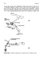
A
typical compressor cylinder
inert
buffer
gas
arrangement
is
shown
in
Figure
11-25.
EXAMPLE
PROBLEM
Grveo:
Late
in the
field
life
it is
desirable
to
compress
the 100
MMscfd
for the
example field downstream
of the
separator
from
800
psig
at
100°F
to
1,000 psig.
An
engine-driven separable compressor
is
available
from
sur-
plus.
The
engine
is
rated
for
1,600
hp at 900
rpm.
Horsepower
is
propor-
tional
to
speed.
The
compressor
frame
has six
7-in.
bore
by
6.0-in.
stroke
double-acting cylinders with
a
minimum clearance
of
17.92%,
a rod
load
limit
of
25,000
Ib,
and rod
diameter
of
1.75
in.
Assume
k =
1.26,
Z
s
=
0.88,
and
Z
d
=
0.85.
Figure
11-25.
Typical
compressor
cylinder inert
buffer
gas
arrangement.
(Courtesy
ofDresser-Rana
Company.)
Compute
discharge temperature, volumetric
efficiency,
required clear-
ance,
rod
load,
and
required horsepower
for the
given conditions. Also
calculate
the
lowest
suction
pressure
at
which this
unit
can
compress
100
MMscfd.
Spjujioji:
I.
Calculate
the gas
discharge temperature
322
Design
of
GAS-HANDLING
Systems
and
Facilities
Reciprocating
Compressors
323
2.
Calculate
the
volumetric
efficiency
3.
Calculate
the
required clearance
Convert
to
standard conditions:
At
the
present operating condition,
the
throughput
is too
high.
One
can
decrease
throughput
by
reducing
speed,
increasing
clearance,
which
will reduce volumetric
efficiency,
using
a
thicker cylinder
liner
to
reduce cylinder volume,
or
lowering suction pressure.
324
Design
of
GAS-HANDLING
Systems
and
Facilities
(a)
Calculate required
rpm
to
give desired throughput:
(b)
Calculate
the
clearance that would
be
needed
to
reduce
the
throughput
from
106.9 MMscfd
to 100
MMscfd:
Keep
PD
tot
constant,
but
lower
the
efficiency.
Now
back calculate
for the
clearance that must
be
added
to
pro-
duce
this volumetric
efficiency.
(c)
Calculate
the
size liner required
to
reduce piston displacement:
Assume
E
v
remains constant. This
may
have
to be
determined
once
a
drawing
of the
specific
cylinder
and
liner
is
available.
However,
it
should
not
vary greatly.
The PD
required
is:
Reciprocating Compressors
325
4.
Calculate
the rod
load
The
calculated
rod
load
for
both
the
compression
and
tension modes
are
within
the
25,000-Ib
maximum
rod
load
limit,
5.
Calculate
the
required horsepower needed
for the
given conditions:
326
Design
of
GAS-HANDLING
Systems
and
Facilities
This
is
less
than
is
available
from
our
engine.
6,
Calculate
the
lowest
suction pressure.
If
we use the
minimum clearance,
It
would
be
possible
to
recalculate this
by
choosing
a new
value
for
Z
s
and
calculating
a new
E
v
for
this condition,
but the
results will
not
change materially.
By
inspection, neither horsepower,
rod
load,
nor
discharge temperature will limit this suction pressure.
CHAPTIR
12
Mechanical
Design
of
Pressure
Vessels*
Previous chapters
of
this book,
as
well
as
Volume
1,
discuss concepts
for
determining
the
diameter
and
length
of
various pressure vessels.
Volume
1
examined
the
various
codes
and
equations
for
choosing
the
wall thickness
of
piping. This chapter addresses
the
selection
of
design pressure rating
and
wall thickness
of
pressure vessels.
It
also presents
a
procedure
for
esti-
mating
vessel weight
and
includes some example design details.
The
purpose
of
this chapter
is to
present
an
overview
of
simple
con-
cepts
of
mechanical design
of
pressure
vessels
that must
be
understood
by
a
project engineer specifying
and
purchasing this equipment. Most
pressure vessels
in the
U.S.
and
many
in
other parts
of the
world
are
designed
and
inspected according
to the
American Society
of
Mechanical
Engineers' Boiler
and
Pressure Vessel Code (ASME Code). Because
the
ASME Code contains much more
detail
than
can be
covered
in a
single
chapter
of a
general textbook such
as
this
one,
the
project engineer
should
have access
to a
copy
of the
ASME Code
and
should become
*Reviewed
for the
1999
edition
by
K.
S.
Chiou
of
Paragon Engineering
Services,
Inc.
327
328
Design
of
GAS-HANDLING
Systems
and
Facilities
familiar
with
its
general contents.
In
particular, Section VIII
of the
code,
"Pressure
Vessels,"
is
particularly important. Countries that
do not use
the
ASME Code have similar documents
and
requirements.
The
proce-
dures
used
in
this chapter that refer specifically
to the
ASME Code
are
generally
applicable
in
other countries,
but
should
be
checked
against
the
applicable code.
In
federal
water
of the
U.S.
and in a few
states,
all
pressure
vessels
must
be
designed
and
inspected
in
accordance
with
the
ASME Code.
In
many
states, however, there
is no
such requirement.
It is
possible
to
pur-
chase
"non-code"
vessels
in
these states
at a
small
savings
in
cost.
Non-
code vessels
are
normally designed
to
code requirements (although there
is
no
certainty that this
is
true),
but
they
are not
inspected
by a
qualified
code inspector
nor are
they necessarily inspected
to the
quality
standards
dictated
by the
code.
For
this reason,
the use of
non-code vessels
should
be
discouraged
to
assure vessel
integrity.
DESIGN
CONSIDERATIONS
Design
Temperature
The
maximum
and
minimum design temperatures
for a
vessel will
determine
the
maximum allowable stress value permitted
for the
material
to
be
used
in the
fabrication
of the
vessel.
The
maximum temperature
used
in the
design should
not be
less than
the
mean metal temperature
expected under
the
design operating conditions.
The
minimum tempera-
ture
used
in the
design should
be the
lowest
expected
in
service
except
when
lower temepratures
are
permitted
by the
rules
of the
ASME Code,
In
determining
the
minimum
temperature,
such factors
as the
lowest
operating temperature, operational upset, auto-refrigeration, ambient
temperature,
and any
other source
of
cooling should
all be
considered.
If
necessary,
the
metal temperature should
be
determined
by
computation
using
accepted
heat transfer procedures
or by
measurement
from
equip-
ment
in
service under equivalent operating conditions.
Design
Pressure
The
design
pressure
for a
vessel
is
called
its
"Maximum Allowable
Working Pressure" (MAWP).
In
conversation this
is
sometimes
referred
to
simply
as the
vessel's
"working pressure."
The
MAWP determines
the
setting
of the
relief valve
and
must
be
higher
than
the
normal
pressure
of
Mechanical
Design
of
Pressure
Vessels
329
the
process
contained
in the
vessel, which
is
called
the
"operating
pres-
sure"
of the
vessel.
The
operating pressure
is
fixed
by
process
conditions.
Table
12-1
recommends
a
minimum differential between operating pres-
sure
and
MAWP
so
that
the
difference
between
the
operating pressure
and
the
relief valve
set
pressure provides
a
sufficient
cushion.
If the
oper-
ating
pressure
is too
close
to the
relief
valve setting, small surges
in
oper-
ating pressure could cause
the
relief valve
to
activate prematurely.
Some vessels have
high-pressure
safety sensors
(PSH)
that shut
in the
inflow
if a
higher-than-normal
pressure
is
detected.
The use of
safety
sensors
is
discussed
in
more detail
in
Chapter
14, The
differential
between
the
operating pressure
and the PSH
sensor
set
pressure should
be as
indicated
in
Table
12-1,
and the
relief valve should
be set at
least
5%
or 5
psi,
whichever
is
greater,
higher than
the PSH
sensor
set
pres-
sure.
Thus,
the
minimum recommended MAWP
for a
vessel operating
at
75
psig with
a PSH
sensor
would
be 105
psig
(75 + 25 + 5); the PSH
sen-
sor is set at 100
psig
and the
relief valve
is set at
105
psig.
Often,
especially
for
small vessels,
it is
advantageous
to use a
higher
MAWP
than
is
recommended
in
Table 12-1.
It may be
possible
to
increase
the
MAWP
at
little
or no
cost
and
thus have greater
future
flexi-
bility
if
process
changes (e.g., greater throughput) require
an
increase
in
operating pressure.
The
MAWP
of the
vessel cannot exceed
the
MAWP
of the
nozzles,
valves,
and
pipe connected
to the
vessel.
As
discussed
in
Volume
1,
Chapter
9,
pipe flanges, fittings
and
valves
are
manufactured
in
accor-
dance
with
industry standard
pressure
rating
classes.
Table 12-2
is a
sum-
mary
of the
more detailed Table
9-11
in
Volume
1
(1st
Edition:
Table
9-
9) and
presents
the
MAWP
of
carbon steel fittings manufactured
in
Table
12-1
Setting
Maximum Allowable Working
Pressures
Minimum
Differential
Between
Operating
Pressure
Operating
and
MAWP
Less than
50
psig
10 psi
5
1
psig
to 250
psig
25 psi
25
1
psig
to 500
psig
10%
of
maximum operating pressure
501
psig
to
1000
psig
50 psi
1001
psig
and
higher
5% of
maximum
operating
pressure
Vessels
with
high-pressure
safety
sensors
have
an
additional
5% or 5
psi,
whichever
is
greater, added
to the
minimum differential.
330
Design
of
GAS-HANDLING
Systems
and
Facilities
accordance with American National Standards Institute (ANSI)
specifi-
cation
B16.5.
If
the
minimum MAWP calculated
from
Table
12-1
is
close
to one of
the
ANSI MAWP listed
in
Table 12-2,
it is
common
to
design
the
pres-
sure
vessel
to the
same MAWP
as the
ANSI
class.
For
example,
the
105-
psig
pressure vessel previously discussed
will
have nozzles, valves
and
fittings
attached
to it
that
are
rated
for 285
psig (ANSI Class
150),
The
increase
in
cost
of
additional vessel
wall
thickness
to
meet
a
MAWP
of
285
psig
may be
small.
Often,
a
slightly higher MAWP than that calculated
from
Table
12-1
is
possible
at
almost
no
additional cost. Once
a
preliminary MAWP
is
selected
from
Table
12-1,
it is
necessary
to
calculate
a
wall thickness
for
the
shell
and
heads
of the
pressure vessel.
The
procedure
for
doing this
is
described
in the
following section.
The
actual wall thickness chosen
for
the
shell
and
heads will
be
somewhat higher than that calculated,
as
the
shells
and
heads will
be
formed
from
readily
available
plates. Thus, once
the
actual wall thickness
is
determined,
a new
MAWP
can be
specified
for
essentially
no
additional cost. (There
will
be a
marginal increase
in
cost
to
test
the
vessel
to the
slightly higher pressure.)
This
concept
can be
especially significant
for a
low-pressure vessel
where
a
minimum
wall
thickness
is
desired.
For
example, assume
the
calculations
for a
50-psig
MAWP vessel indicate
a
wall thickness
of
0.20
in.,
and
it is
decided
to use
!4-in.
plate.
This same plate might
be
used
if a
MAWP
of
83.3 psig were specified. Thus,
by
specifying
the
higher
MAWP
(83.3 psig), additional operating flexibility
is
available
at
essen-
tially
no
increase
in
cost.
Many operators
specify
the
MAWP based
on
Table
12-2
Summary
ANSI
Pressure
Ratings
Material
Group
1.1
Class
150
300
400
600
900
1500
2500
~20°FtolOO°
285
740
990
1480
2220
3705
6170
MAWP,
psig
F
100°Fto200°F
250
675
900
1350
2025
3375
5625
Mechanical
Design
of
Pressure
Vessels
331
process
conditions
in
their
bids
and ask the
vessel
manufacturers
to
state
the
maximum MAWP
for
which
the
vessel could
be
tested
and
approved,
Maximum
Allowable
Stress
Values
The
maximum allowable stress
values
to be
used
in the
calculation
of
the
vessel's wall thickness
are
given
in the
ASME
Code
for
many
different
materials. These stress values
are a
function
of
temperature. Section
VIII
of
the
ASME
Code,
which governs
the
design
and
construction
of all
pres-
sure
vessels with operating pressures greater
than
15
psig,
is
published
in
two
divisions. Each sets
its own
maximum allowable stress values. Divi-
sion
1,
governing
the
design
by
Rules,
is
less stringent
from
the
standpoint
of
certain
design
details
and
inspection
procedures,
and
thus
incorporates
a
higher
safety
factor
of 4. For
example,
if a
60,000
psi
tensile strength
material
is
used,
the
maximum allowable stress value
is
15,000
psi.
On the
other hand, Division
2
governs
the
design
by
Analysis
and
incorporates
a
lower safety factor
of 3.
Thus,
the
maximum allowable stress value
for a
60,000
psi
tensile strength material will become
20,000
psi.
Many
companies require that
all
their pressure vessels
be
constructed
In
accordance with Division
2
because
of the
more exacting standards.
Others
find
that they
can
purchase less expensive
vessels
by
allowing
manufacturers
the
choice
of
either Division
1 or
Division
2.
Normally,
manufacturers
will choose Division
I
for
low-pressure
vessels
and
Divi-
sion
2 for
high-pressure vessels.
The
maximum allowable
stress
values
at
normal temperature range
for
the
steel plates most commonly used
in the
fabrication
of
pressure vessels
are
given
in
Table 12-3.
For
stress values
at
higher temperatures
and for
other
materials,
the
latest edition
of the
ASME Code should
be
referenced.
Determining
Wall
Thickness
The
following formulas
are
used
in the
ASME Code Section VIII,
Division
1 for
determining wall thickness:
Wall
thickness—cylindrical
shells
332
Design
of
GAS-HANDLING
Systems
and
Facilities
Table
12-3
Maximum
Allowable
Stress
Value
for
Common
Steels
Metal
Temperature
Carbon
Steel
Plates
and
Sheets
Low
Alloy
Steel
Plates
High
Alloy
Steel
Plates
Not
Lower
Than
Not
Exceeding
SA-516
Grade
55
Grade
60
Grade
65
Grade
70
SA-285 Grade
A
Grade
B
Grade
C
SA-36
SA-387 Grade
2,
cl.
1
Grade
12,
cl.l
Grade
11,
cl. 1
Grade
22,
cl.l
Grade21,cl.l
Grade
5,
cl.l
Grade
2,
cl.2
Grade
1.2, cl.2
Grade
11,
cl.2
Grade
22,
cl.2
Grade
21,
cl.2
Grade
5,
cl.2
SA-203 Grade
A
Grade
B
Grade D
Grade
E
SA-240 Grade
304
Grade 304L
Grade
3
16
Grade316L
ASME
Section
Vili
Div.
1
Div,
2
-20°F
~20°F
650°F
100°F
1
3,800
15,000
16,300
17,500
11,300
12,500
13,800
12,700
13,800
13,800
15,000
15,000
15,000
13,900
1
7,500
16,300
18,800
17,700
17,700
17,400
16,300
17,500
16,300
17,500
11,200
—
12,300
10,200
18,300
20,000
21
700
23,300
15,000
16,700
18,100
1
6,900
18,300
18,300
20,000
20,000
20,000
20,000
23,300
21,700
25,000
25,000
25,000
25.000
21.700
23,300
21,700
23,300
20,000
16,700
20,000
16,700
Wall
thickness—2:1
ellipsoidal heads
Wall
thickness—hemispherical
heads
Mechanical
Design
of
Pressure
Vessels
333
\X7a1l
fht/»l^~ri«aoe
r»r»nAC
where
S =
maximum allowable stress value,
psi
t =
thickness, excluding corrosion allowance,
in.
P =
maximum allowable working pressure, psig
r =
inside radius before corrosion allowance
is
added,
in.
d
=
inside diameter before corrosion allowance
is
added,
in,
E
=
joint
efficiency,
see
Table
12-4
(Most vessels
are
fabricated
in
accordance with Type
of
Joint
No. 1.)
a =
1
A
the
apex
of the
cone
Figure
12-1
defines
the
various types
of
heads.
Most production
facili-
ty
vessels
use
ellipsoidal
heads because they
are
readily available,
nor-
mally
less expensive,
and
take
up
less room
than
hemispherical
heads.
Cone-bottorn vertical
vessels
are
sometimes
used where
solids
are
anticipated
to be a
problem. Most cones have either
a 90°
apex
(a =
45°)
or
a 60°
apex
(a =
30°).
These
are
referred
to
respectively
as a
"45°"
or
"60°"
cone because
of the
angle each makes
with
the
horizontal. Equa-
tion
12-4
is for the
thickness
of a
conical head that contains pressure.
Some operators
use
internal cones within vertical vessels
with
standard
ellipsoidal
heads
as
shown
in
Figure
12-2.
The
ellipsoidal
heads contain
the
pressure,
and
thus
the
internal cone
can be
made
of
very thin steel.
Table
12-4
lists joint efficiencies that should
be
used
in
Equations
12-1
to
12-4.
This
is
Table
UW-12
in the
ASME Code.
Table
12-5
lists some
of the
common material types used
to
construct
pressure vessels. Individual operating companies have their
own
stan-
dards, which
differ
from
those listed
in
this table.
Corrosion Allowance
Typically,
a
corrosion allowance
of
0.125
in. for
non-corrosive service
and
0.250
in. for
corrosive service
is
added
to the
wall thickness calculat-
ed
in
Equations
12-1
to
12-4.
INSPECTION
PROCEDURES
All
ASME Code
vessels
are
inspected
by an
approved Code inspector.
The
manufacturer
will
supply
Code papers signed
by the
inspector.
The
334
Design
of
GAS-HANDLING
Systems
and
Facilities
Figure
12-1.
Pressure
vessel
shapes.
nameplate
on the
vessel will
be
stamped
to
signify
it has met the
require-
ments
of the
Code.
One of
these requirements
is
that
the
vessel
was
tested
to
1.5
times
MAWP.
However, this
is
only
one of the
requirements.
The
mere
fact
that
a
vessel
is
tested
to
1.5
times MAWP does
not
signify
that
it
has met all the
design
and
quality assurance
safety
aspects
of the
Code.
It
must
be
pointed
out
that
a
Code
stamp
does
not
necessarily mean
that
the
vessel
is
fabricated
in
accordance with critical nozzle dimensions
or
internal devices
as
required
by the
process.
The
Code inspector
is
only
interested
in
those aspects that relate
to the
pressure-handling integrity
of
the
vessel.
The
owner must
do his own
inspection
to
assure that nozzle
locations
are
within tolerance, vessel internals
are
installed
as
designed,
coatings
are
applied properly,
etc.
Mechanical
Design
of
Pressure
Vessels
335
Figure
12-2.
Internal
cone
vessel.
ESTIMATING
VESSEL
WEIGHTS
It
is
important
to be
able
to
estimate vessel weights, since most cost
estimating
procedures
start
with
the
weight
of the
vessel.
The
vessel
weight, both empty
and
full
with water,
may be
necessary
to
adequately
design
a foundation or to
assure that
the
vessel
can be
lifted
or
erected
once
it
gets
to the
construction
site.
The
weight
of a
vessel
is
made
up of the
weight
of the
shell,
the
weight
of the
heads,
and the
weight
of
internals, nozzles, pedestals,
and
skirts.
The
last
two
terms
are
defined
in
Figure
12-3.
(text continued
on
page
339)