Electric Machinery Fundamentals (Solutions Manual) Part 2 ppt
Bạn đang xem bản rút gọn của tài liệu. Xem và tải ngay bản đầy đủ của tài liệu tại đây (120.64 KB, 10 trang )
(a)
This
generator is Y-connected, so
L A
I
I
=
.
At rated conditions, the line and phase current
in this generator is
I
I
1000 kVA
251 A
=
=
P
=
=
at an
angle of –36.87
°
A
L
(
3
3
2300
)
V
L
V
=
=
. The internal generated voltage
of
the
machineThe phase voltage of this
machine
is
⎞
T
/
V
V
3
1328 V
is
=
+
E
V
+
I
I
A
A
⎞
A
S
A
R
jX
1328
0
(
0.15
)(
251
36.87
A
)
(
1.1
)(
251
36.87
A
)
E
A
=
°
+
&
°
j
+
&
°
E
A
1537
7.4
V
=
°
The input power
to this generator is equal to
the
output power plus losses.
The
rated output
power is
(
)(
)
OUT
P
1000 kVA
0.8
800 kW
=
=
2
(
)
=
=
2
(
)
&
=
CU
3
A
A
P
I
3
R
251 A
0.15
28.4 kW
F&
P
=
W
24 kW
co
P
re
=
18 kW
st
P
ray
=
(assumed 0)
=
+
+
+
+
=
IN
OUT
P
P
CU
P
F&W
P
core
P
stray
P
870.4 kW
η
OUT
P
100%
800 kW
100%
91.9%
=
⋅
=
⋅
=
IN
P
870.4 kW
(b)
If the generator
is loaded to rated kVA with
lagging loads,
the
phase
voltage
is
φ
V
=
1328
0
°
V
and
the
internal generated voltage is
E
A
1537
7.4
V
=
°
. Therefore, the phase voltage at no-
load would be
V
⎞
1537
0
V
=
°
.
The voltage
regulation would
be:
1537
1328
RV
100%
15.7%
=
⋅
=
1328
(c)
If the generator
is loaded to rated kVA with leading
loads, the
phase
voltage
is
φ
V
the internal
generated voltage
is
=
1328
0
°
V
and
=
+
E
V
+
I
I
A
A
⎞
A
S
A
R
jX
1328
0
(
)
0.
(
15
251
36.87
A
)
(
1.1
)(
251
36.87
A
)
E
A
=
°
+
&
°
j
+
&
°
E
A
1217
11.5
=
V
°
The voltage regulation
would be:
1217
1328
RV
100%
8.4%
=
⋅
=
1328
(d)
If
the
generator
is
loaded
to
rated
kVA
at
unity
power
factor,
the
phase
voltage
is
V
φ
=
1328
0
°
V
and the internal generated voltage
is
=
+
E
V
+
I
I
A
A
⎞
A
S
A
R
jX
115
1328
0
(
0.15
)(
)
251
0
A
(
1.1
)(
)
251
0
A
E
A
=
°
+
&
°
j
+
&
°
E
A
1393
11.4
=
V
°
The voltage regulation
would be:
1393
1328
RV
100%
4.9%
=
⋅
=
1328
(e)
For
this
problem,
we
will
assume
that
the
terminal
voltage
is
adjusted
to
2300
V
at
no
load
conditions, and see what happens to the voltage as load increases at 0.8 lagging, unity, and
0.8
leading
power factors. Note that the maximum current will be
251
A in any case.
A phasor
diagram
representing
the situation at
lagging
power factor is
shown
below:
E
A
⎝
™
⎝
I
A
By the Pythagorean
Theorem,
⎝
jX
I
V
⎞
S
A
I
R
AA
2
(
)
=
+
cos
+
sin
(
)
2
+
co
⎝
⎝
s
sin
⎝
2
⎝
A
A
E
V
⎞
R
A
I
S
A
X
I
S
A
X
I
A
R
S
I
2
(
)
=
cos
s
in
2
co
⎝
⎝
s
s
in
⎝
⎝
⎞
A
S
V
E
A
X
I
A
S
R
I
A
A
R
I
S
A
X
I
A phasor diagram representing the situation at
leading power
factor
is shown below:
E
A
jX
I
S
A
⎝
I
A
I
R
™
⎝
A
A
⎝
⎞
V
By the Pythagorean
Theorem,
2
(
=
+
cos
sin
)
(
)
2
+
co
⎝
⎝
s
+
sin
⎝
2
⎝
A
A
E
V
⎞
R
A
I
S A
X
I
S A
X
I
A
R
S
I
2
(
)
=
cos
s
+
in
2
co
⎝
⎝
s
s
+
in
⎝
⎝
⎞
A
S
V
E
A
X
I
A
S
R
I
A
A
R
I
S
A
X
I
A phasor diagram representing the situation at
unity power factor is shown
below:
E
A
™
I
A
V
⎞
116
jX
I
S
A
R
I
AA
By the Pythagorean
Theorem,
(
2
2
= +
)
2
A
S
E V
⎞
A
X I
2
(
)
=
2
⎞
A
S
V
E
A
X
I
The MATLAB
program
is shown below takes advantage of this
fact.
% M-file: prob5_4e.m
%
M-file to calculate and
plot the
terminal voltage
% of a synchronous
generator as a
function of load
% for
power
factors of 0.8 lagging, 1.0,
and 0.8 leading.
% Define
values for this
generator
EA
= 1328;
% Internal gen voltage
I = 0:2.51:251;
% Current values (A)
R = 0.15;
% R (ohms)
X = 1.10;
% XS (ohms)
% Calculate
the
voltage for
the lagging PF case
VP_lag = sqrt( EA^2 - (X.*I.*0.8
- R.*I.*0.6).^2
)
- R.*I.*0.8 -
X.*I.*0.6;
VT_lag = VP_lag .* sqrt(3);
% Calculate
the voltage for
the leading
PF case
VP_lead = sqrt( EA^2 - (X.*I.*0.8
+ R.*I.*0.6).^2
)
- R.*I.*0.8 +
X.*I.*0.6;
VT_lead = VP_lead .* sqrt(3);
% Calculate
the voltage for
the unity PF case
VP_unity
= sqrt( EA^2
- (X.*I).^2
);
VT_unity
= VP_unity .* sqrt(3);
% Plot the terminal voltage
versus load
plot(I,abs(VT_lag),'b-','LineWidth',2.0);
hold on;
plot(I,abs(VT_unity),'k ','LineWidth',2.0);
plot(I,abs(VT_lead),'r ','LineWidth',2.0);
title
('\bfTerminal Voltage
Versus Load');
xlabel ('\bfLoad (A)');
ylabel ('\bfTerminal Voltage (V)');
legend('0.8
PF
lagging','1.0 PF','0.8 PF
leading');
axis([0 260
1500 2500]);
grid on;
hold off;
The
resulting plot is
shown below:
117
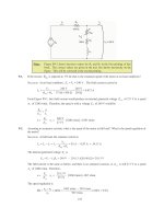
5-5.
Assume that the field current of the generator in Problem 5-2 has been adjusted so
that
it
supplies
rated
voltage when loaded with rated current at unity power factor.
(You
may
ignore
the
effects
of
answering these
questions.)
R
A
when
(a)
What
is the torque
angle
™
of the generator when supplying
rated current at unity power factor?
(b)
When this
generator
is running at full
load with
unity power factor, how
close is it to
the
static
stability
limit of the
machine?
S
OLUTION
(a)
The
torque
™
angle can be
found
by calculating
E
A
:
=
+
E
V
+
I
I
A
A
⎞
A S A
R
jX
1328
0
(
0.15
)(
)
251
0
A
(
1.1
)(
)
251
0
A
E
A
=
°
+
&
°
j
+
&
°
E
A
1393
11.4
=
V
°
Thus the
torque angle
™
= 11.4
°
.
(b)
The static stability limit
occurs
at
™
=
°
90
.
This generator is a very long way
from
that
limit.
If we
ignore the internal resistance of the generator, the output
power will be given
by
P
A
V
E
sin
=
3
⎞
™
X
S
and the output power is proportional to
sin
™
.
Since
sin
11.4
°=
0.198
, and
sin
90
1.
°=
stability limit
is about 5 times
the
current output power of the generator.
00
, the static
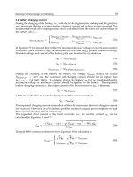
5-6.
A 480-V 400-kVA 0.85-PF-lagging 50-Hz four-pole
-connected generator is driven by a 500-hp diesel
engine
and
is
used as a standby or emergency generator. This machine can also be paralleled with the
normal power supply (a very
large power system) if
desired.
(a)
What
are the
conditions required
for
paralleling the emergency generator with the existing
power
system? What
is the generator’s rate of shaft rotation after paralleling occurs?
118
(b)
If
the
generator
is
connected
to
the power system and
is initially floating on
the line, sketch the resulting
magnetic fields and
phasor
diagram.
(c)
The governor setting
on the diesel is now increased. Show
both by means of house diagrams and
by
means of phasor
diagrams what happens to the generator.
How
much reactive power
does the generator
supply now?
(d)
With the diesel generator now supplying
real power to the
power
system,
what
happens
to the generator as
its field current is increased and
decreased? Show this behavior
both
with phasor diagrams
and
with
house diagrams.
S
OLUTION
(a)
To
parallel
this generator to the large power system, the required conditions
are:
1.
The generator must have
the
same voltage
as the power
system.
2.
The
phase sequence
of the oncoming generator must be the
same as
the phase sequence of the
power system.
3.
The
frequency
of the oncoming
generator
should
be
slightly
higher than the frequency of the
running system.
4.
The circuit breaker connecting the two systems together should be shut when
the
above conditions
are met
and the generator is
in phase
with the power
system.
After paralleling, the generator’s shaft will
be rotating at
120
120
(
)
50 Hz
n
f
e
=
=
1500 r/
=
min
P
m
4
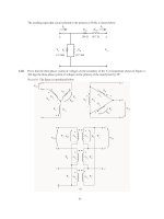
(b)
The magnetic field and phasor diagrams immediately after paralleling are shown below:
BB
E
S R A
I
jX
I
S A
B
net
A
V
⎞
(c)
When
the
governor
setpoints
on
the generator are increased, the emergency generator begins
to
supply
more
power to the loads, as shown below:
f
e
E
A
jX
I
S
A
I
P
P
P
1
sys
A
V
⎞
2
P
G
Note that as the load
increased with
E
A
reactive power.
constant, the generator began to consume a small amount of
(d)
With
the generator
now
supplying power to
the system,
an increase in field current increases the
reactive power supplied to the
loads, and a decrease in field current decreases the reactive
power supplied to
the loads.
119
V
T
I
A1
E
A1
E
A2
E
A3
QQ QQ
3
G
2
1
Q
sys
I
A2
I
⎞
V
jX
I
S A
A3
V
T
I
A2
A2
EE
A1
jX
I
S A
Q Q Q
G
1
2
Q
sys
I
A1
V
⎞
5-7.
A
13.8-kV
10-MVA
0.8-PF-lagging
60-Hz
two-pole
Y-connected
steam-turbine
generator
has
a
synchronous reactance of 12
&
per phase and
an armature
resistance of 1.5
&
per phase.
This
generator
is
operating in
parallel
with a large power
system
(infinite bus).
(a)
What
is the magnitude of
E
A
at
rated conditions?
(b)
What
is the torque
angle of the generator at
rated conditions?
(c)
If the field current is constant, what is the maximum power possible out of this
generator?
How
much
reserve power
or
torque does this
generator
have at full load?
(d)
At the absolute maximum power possible,
how much
reactive power will this
generator
be
supplying or
consuming? Sketch the corresponding phasor diagram.
(Assume
I
F
is still unchanged.)
S
OLUTION
(a)
The
phase voltage
of
this
generator at rated conditions is
V
13,
800 V
7967 V
⎞
=
=
3
The armature current per
phase
at rated conditions is
S
10,
000,
=
=
000 VA
418 A
=
A
I
3
3
(
)
13,800
V
T
V
Therefore, the internal generated voltage
at
rated
conditions
is
=
+
+
A
A
E
V
⎞
A
I
S
A
R
jX
I
7967
0
(
)
1.5
(
418
36.87
A
)
(
12.0
)(
418
36.87
A
)
E
A
=
°
+
&
°
j
+
&
°
E
A
12,
040
17.6
V
=
°
120
The magnitude of
E
A
is 12,040 V.
(b)
The torque angle of the generator
at rated
conditions is
™
= 17.6
°
.
(c)
Ignoring
R
A
, the
maximum output
power
of the generator
is given by
3
3
(
)
7967 V
(
12,040 V
)
P
⎞
A
V
E
=
=
=
MAX
X
S
12
&
24.0 MW
The power at maximum load is 8 MW, so the maximum output power is three times the
full
load output
power.
(d)
The phasor diagram at these conditions is
shown below:
E
A
jX
I
S A
I
A
R
I
A A
V
⎞
Under these conditions,
the
armature current
is
A
E
V
I
⎞
12,
040
90
V
°
-
7967
0
V
°
1194
40.6
A
=
=
=
°
A
1.5
12.0
+
+
&
A S
R
jX
j
The reactive
power produced by the generator at this
point is
3
sin
3
(
)
7967 V
(
119
=
=
⎞
⎝
A
Q
V
I
4
A
)
sin
(
0
40.6
)
18
°
.6
MVA
°
R
=
The generator is actually consuming
reactive power at this time.
5-8.
A 480-V,
100-kW, two-pole, three-phase, 60-Hz
synchronous generator’s
prime
mover
has
a
no-load speed of
3630 r/min and a full-load speed of 3570 r/min. It is operating
in
parallel
with
a 480-V,
75-kW,
four- pole,
60-Hz synchronous generator whose prime mover has a no-load speed of 1800 r/min and a
full-load speed
of 1785
r/min.
The loads supplied
by the two generators consist of 100 kW at 0.85 PF
lagging.
(a)
Calculate
the
speed droops of generator 1 and
generator
2.
(b)
Find
the operating frequency of
the
power system.
(c)
Find
the power being
supplied by
each of the generators in this
system.
(d)
If
V
T
is
460
V, what must the generator’s
operators
do to correct
for the low
terminal
voltage?
S
OLUTION
The no-load frequency
of
generator 1
corresponds to a frequency
of
(
)
3630 r/min
(
2
)
f
m
n
P
=
=
=
nl1
120
120
60.5 Hz
The full-load frequency of generator
1 corresponds
to a frequency of