Visual C++ and MFC Fundamentals programming phần 4 ppsx
Bạn đang xem bản rút gọn của tài liệu. Xem và tải ngay bản đầy đủ của tài liệu tại đây (675.78 KB, 70 trang )
Visual C++ and MFC Fundamentals Chapter 8 GDI Orientation and Transformations
© FunctionX, Inc. 211
font.DeleteObject();
}
To produce a shadow effect, you can add another copy of the same text on a slightly
different location and call the CDC::SetBkMode() method. Here is an example:
void CExoView::OnDraw(CDC* pDC)
{
CExoDoc* pDoc = GetDocument();
ASSERT_VALID(pDoc);
CFont font;
font.CreatePointFont(920, "Garamond");
CFont *pFont = pDC->SelectObject(&font);
pDC->SetBkMode(TRANSPARENT);
pDC->SetTextColor(RGB(110, 185, 250));
pDC->TextOut(26, 24, "Christine", 9);
pDC->SetTextColor(RGB(0, 0, 255));
pDC->TextOut(20, 18, "Christine", 9);
pDC->SelectObject(pFont);
font.DeleteObject();
}
One of the most complete means of creating a font is by using the CFont::CreateFont()
method. Its syntax is:
BOOL CreateFont(int nHeight,
int nWidth,
int nEscapement,
int nOrientation,
int nWeight,
BYTE bItalic,
BYTE bUnderline,
BYTE cStrikeOut,
Chapter 8 GDI Orientation and Transformations Visual C++ and MFC Fundamentals
212 © FunctionX, Inc.
BYTE nCharSet,
BYTE nOutPrecision,
BYTE nClipPrecision,
BYTE nQuality,
BYTE nPitchAndFamily,
LPCTSTR lpszFacename);
The nHeight argument is the height applied to the text.
The nWidth value is the desired width that will be applied on the text.
The nEscapement is the angle used to orient the text. The angle is calculated as a multiple
of 0.1 and oriented counterclockwise.
The nOrientation is the angular orientation of the text with regards to the horizontal axis.
The nWeight is used to attempt to control the font weight of the text because it is affected
by the characteristics of the font as set by the designer. It holds values that displays text
from thin heavy bold. The possible values are:
Constant Value Constant Value
FW_DONTCARE 0 FW_THIN 100
FW_EXTRALIGHT 200 FW_ULTRALIGHT 200
FW_LIGHT 300
FW_NORMAL 400 FW_REGULAR 400
FW_MEDIUM 500
FW_SEMIBOLD 600 FW_DEMIBOLD 600
FW_BOLD 700
FW_EXTRABOLD 800 FW_ULTRABOLD 800
FW_BLACK 900 FW_HEAVY 900
The bItalic specifies whether the font will be italicized (TRUE) or not (FALSE).
The bUnderline is used to underline (TRUE) or not underline (FALSE) the text.
The cStrikeOut is specifies whether the text should be stroke out (TRUE) or not (FALSE)
with a line.
The nCharSet, specifies the character set used. The possible values are:
Constant Value
ANSI_CHARSET 0
DEFAULT_CHARSET 1
SYMBOL_CHARSET 2
SHIFTJIS_CHARSET 128
OEM_CHARSET 255
The nOutPrecision controls the amount precision used to evaluate the numeric values
used on this function for the height, the width, and angles. It can have one of the
following values: OUT_CHARACTER_PRECIS, OUT_STRING_PRECIS,
OUT_DEFAULT_PRECIS, OUT_STROKE_PRECIS, OUT_DEVICE_PRECIS,
OUT_TT_PRECIS, OUT_RASTER_PRECIS
If some characters may be drawn outside of the area in which they are intended, the
nClipPrecision is used to specify how they may be clipped. The possible value used are
CLIP_CHARACTER_PRECIS, CLIP_MASK, CLIP_DEFAULT_PRECIS,
CLIP_STROKE_PRECIS, CLIP_ENCAPSULATE, CLIP_TT_ALWAYS,
CLIP_LH_ANGLES.
Visual C++ and MFC Fundamentals Chapter 8 GDI Orientation and Transformations
© FunctionX, Inc. 213
The nQuality specifies how the function will attempt to match the font's characteristics.
The possible values are DEFAULT_QUALITY, PROOF_QUALITY, and
DRAFT_QUALITY.
The nPitchAndFamily specifies the category of the font used. It combines the pitch and
the family the intended font belongs to. The pitch can be specified with
DEFAULT_PITCH, VARIABLE_PITCH, or FIXED_PITCH. The pitch is combined
using the bitwise OR operator with one of the following values:
Value Description
FF_DECORATIVE Used for a decorative or fancy font
FF_DONTCARE Let the compiler specify
FF_MODERN Modern fonts that have a constant width
FF_ROMAN Serif fonts with variable width
FF_SCRIPT Script-like fonts
FF_SWISS Sans serif fonts with variable width
The lpszFacename is the name of the font used.
Once you have created a font, you can select it into the device context and use it it for
example to draw text.
After using a font, you should delete it to reclaim the memory space its variable was
using. This is done by calling the CGdiObject::DeleteObject() method.
Here is an example:
void CExoView::OnDraw(CDC* pDC)
{
CFont font;
font.CreateFont(46, 28, 215, 0,
FW_NORMAL, FALSE, FALSE, FALSE, ANSI_CHARSET,
OUT_DEFAULT_PRECIS, CLIP_DEFAULT_PRECIS, DEFAULT_QUALITY,
DEFAULT_PITCH | FF_ROMA N, "Times New Roman");
CFont *pFont = pDC->SelectObject(&font);
pDC->TextOut(20, 128, "Euzhan Palcy", 12);
pDC->SelectObject(pFont);
font.DeleteObject();
}
Chapter 8 GDI Orientation and Transformations Visual C++ and MFC Fundamentals
214 © FunctionX, Inc.
Remember that once an object such as a font has been selected, it remains in the device
context until further notice. For example, if you have created and selected a font, any text
you draw would follow the characteristics of that font. If you want another font, you must
change the previously selected font.
The computer uses the default black color to draw the text. Once again, if you want to
draw text with a different color, you can first call the CDC::SetTextColor() method and
specify the color of your choice.
The CFont::CreateFont() method is used to specify all characteristics of a font in one
step. Alternatively, if you want to specify each font property, you can declare a
LOGFONT variable and initialize it. It is defined as follows:
typedef struct tagLOGFONT {
LONG lfHeight;
LONG lfWidth;
LONG lfEscapement;
LONG lfOrientation;
LONG lfWeight;
BYTE lfItalic;
BYTE lfUnderline;
BYTE lfStrikeOut;
BYTE lfCharSet;
BYTE lfOutPrecision;
BYTE lfClipPrecision;
BYTE lfQuality;
BYTE lfPitchAndFamily;
TCHAR lfFaceName[LF_FACESIZE];
} LOGFONT, *PLOGFONT;
This time, you do not have to provide a value for each member of the structure and even
if you do, you can supply values in the order of your choice. For any member whose
value is not specified, the compiler would use a default value but you may not like some
of the default values. Therefore, you should specify as many values as possible.
After initializing the LOGFONT variable, call the CFont::CreateFontIndirect() method.
Its syntax is:
Visual C++ and MFC Fundamentals Chapter 8 GDI Orientation and Transformations
© FunctionX, Inc. 215
BOOL CreateFontIndirect(const LOGFONT* lpLogFont);
When calling this member function, pass the LOGFONT variable as a pointer,
lpLogFont.
To select the selected font, call the CDC::SelectObject() method. Once done, you can use
the new font as you see fit. Here is an example:
void CExoView::OnDraw(CDC* pDC)
{
CFont font;
LOGFONT LogFont;
LogFont.lfStrikeOut = 0;
LogFont.lfUnderline = 0;
LogFont.lfHeight = 42;
LogFont.lfEscapement = 0;
LogFont.lfItalic = TRUE;
font.CreateFontIndirect(&LogFont);
CFont *pFont = pDC->SelectObject(&font);
pDC->TextOut(20, 18, "James Kolowski", 14);
pDC->SelectObject(pFont);
font.DeleteObject();
}
7.4.4 Font Retrieval
If some text is displaying and you want to get the font properties of that text, you can call
the CDC::GetLogFont() method. Its syntax is:
int GetLogFont(LOGFONT * pLogFont);
To get the current font characteristics on a device context, pass a LOGFONT variable as
pointer to this method. After execution, it returns the LOGFONT argument with these
characteristics. If this method succeeds, it returns TRUE or non-zero. It it fails, it returns
FALSE or 0.
Here is an example:
void CAboutDlg::OnButton1()
{
CFont *font;
Chapter 8 GDI Orientation and Transformations Visual C++ and MFC Fundamentals
216 © FunctionX, Inc.
LOGFONT LogFont;
font = this->GetFont();
font ->GetLogFont(&LogFont);
char StrFont[40];
strcpy(StrFont, LogFont.lfFaceName);
CClientDC dc(this);
dc.TextOut(58, 120, StrFont, strlen(StrFont));
}
7.5 Pens
7.5.1 Introduction
In the previous lesson, we mentioned that, in order to draw, two primary objects are
needed: a platform and a tool. So far, we were using the platform, called a device context.
We introduced the main device context class as the CDC class. To draw, we have been
using a pointer to CDC. Now, we need to realize that, declaring a CDC variable does not
just give us access to the device context, it also initializes it.
The device context is a combination of the platform on which the drawing is performed
and the necessary tools to draw on it. As such, when declaring a CDC variable, it also
creates and selects a black pen. This is why we have been able to draw lines and other
shapes so far.
7.5.2 The Fundamentals of a Pen
A pen is a tool used to draw lines and curves on a device context. In the graphics
programming, a pen is also used to draw the borders of a geometric closed shape such as
a rectangle or a polygon.
To make it an efficient tool, a pen must produce some characteristics on the lines it is
asked to draw. These characteristics can range from the width of the line drawn to their
colors, from the pattern applied to the level of visibility of the lines. To manage these
properties, Microsoft Windows considers two types of pens: cosmetic and geometric.
A pen is referred to as cosmetic when it can be used to draw only simple lines of a fixed
width, less than or equal to 1 pixel.
A pen is geometric when it can assume different widths and various ends.
7.5.3 Creating and Selecting a Pen
When you declare a CDC variable, it creates and selects a pen that can draw a 1-pixel
width black line. If you want a more refined pen, the MFC provides the CPen class.
Therefore, the first step in creating a pen is to declare a variable of CPen type, which can
be done using the default constructor as follows:
CPen NewPen;
Visual C++ and MFC Fundamentals Chapter 8 GDI Orientation and Transformations
© FunctionX, Inc. 217
To create a pen, you must specify the desired characteristics. This can be done with
another CPen constructor declared as follows:
CPen(int nPenStyle, int nWidth, COLORREF crColor);
Alternatively, if you want to use a variable declared using the default constructor, you
can then call the CPen::CreatePen() method. Its syntax is:
BOOL CreatePen(int nPenStyle, int nWidth, COLORREF crColor);
The arguments of the second constructor and the CreatePen() method are used to specify
the properties that the pen should have:
The Style: This characteristic is passed as the nPenStyle argument. The possible values of
this argument are:
Value Illustration Description
PS_SOLID
A continuous solid line
PS_DASH
A continuous line with dashed
interruptions
PS_DOT
A line with a dot interruption at every
other pixel
PS_DASHDOT
A combination of alternating dashed and
dotted points
PS_DASHDOTDOT
A combination of dash and double dotted
interruptions
PS_NULL
No visible line
PS_INSIDEFRAME
A line drawn just inside of the border of a
closed shape
To specify the type of pen you are creating, as cosmetic or geometric, use the bitwise OR
operator to combine one of the above styles with one of the following:
?? PS_COSMETIC: used to create a cosmetic pen
?? PS_GEOMTERIC: used to create a geometric pen
If you are creating a cosmetic pen, you can also add (bitwise OR) the PS_ALTERNATE
style to to set the pen at every other pixel.
The Width: The nWidth argument is the width used to draw the lines or borders of a
closed shape. A cosmetic pen can have a width of only 1 pixel. If you specify a higher
width, it would be ignored. A geometric pen can have a width of 1 or more pixels but the
line can only be solid or null. This means that, if you specify the style as PS_DASH,
PS_DOT, PS_DASHDOT, or PS_DASHDOTDOT but set a width higher than 1, the
line would be drawn as PS_SOLID.
The Color: The default color of pen on the device context is black. If you want to control
the color, specify the desired value for the crColor argument.
Based this, using the second constructor, you can declare and initialize a CPen variable as
follows:
CPen NewPen(PS_DASHDOTDOT, 1, RGB(255, 25, 5));
Chapter 8 GDI Orientation and Transformations Visual C++ and MFC Fundamentals
218 © FunctionX, Inc.
The same pen can be created using the CreatePen() method as follows:
CPen NewPen;
NewPen.CreatePen(PS_DASHDOTDOT, 1, RGB(255, 25, 5));
After creating a pen, you can select it into the desired device context variable and then
use it as you see fit, such as drawing a rectangle. Here is an example:
void CExoView::OnDraw(CDC* pDC)
{
CExoDoc* pDoc = GetDocument();
ASSERT_VALID(pDoc);
CPen NewPen;
NewPen.CreatePen(PS_DASHDOTDOT, 1, RGB(255, 25, 5));
pDC->SelectObject(&NewPen);
pDC->Rectangle(20, 22, 250, 125);
}
Once a pen has been selected, any drawing performed and that uses a pen would use the
currently selected pen. If you want to use a different pen, you can either create a new pen
or change the characteristics of the current pen.
After using a pen, between exiting the function or event that created it, you should get rid
of it and restore the pen that was selected previously. Here is an example:
void CExoView::OnDraw(CDC* pDC)
{
CExoDoc* pDoc = GetDocument();
ASSERT_VALID(pDoc);
CPen NewPen;
NewPen.CreatePen(PS_DASHDOTDOT, 6, RGB(255, 25, 5));
CPen* pPen = pDC->SelectObject(&NewPen);
pDC->Rectangle(20, 22, 250, 125);
// Restore the previous pen
pDC->SelectObject(pPen);
}
Visual C++ and MFC Fundamentals Chapter 8 GDI Orientation and Transformations
© FunctionX, Inc. 219
The Win32 API provides the LOGPEN structure that you can use to individually specify
each characteristics of a pen. The LOGPEN structure is created as follows:
typedef struct tagLOGPEN {
UINT lopnStyle;
POINT lopnWidth;
COLORREF lopnColor;
} LOGPEN, *PLOGPEN;
To use this structure, declare a variable of LOGPEN type or a pointer. Then initialize
each member of the structure. If you do not, its default values would be used and the line
not be visible.
The lopnStyle argument follows the same rules we reviewed for the nPenStyle argument
of the second constructor and the CreatePen() method.
The lopnWidth argument is provided as a POINT or a CPoint value. Only the POINT::x
or the CPoint::x value is considered.
The lopnColor argument is a color and can be provided following the rules we reviewed
for colors.
After initializing the LOGPEN variable, call the CPen::CreatePenIndirect() member
function to create a pen. The syntax of the CreatePenIndirect() method is:
BOOL CreatePenIndirect(LPLOGPEN lpLogPen);
The LOGPEN value is passed to this method as a pointer. After this call, the new pen is
available and can be selected into a device context variable for use. Here is an example:
void CExoView::OnDraw(CDC* pDC)
{
CExoDoc* pDoc = GetDocument();
ASSERT_VALID(pDoc);
CPen NewPen;
LOGPEN LogPen;
LogPen.lopnStyle = PS_SOLID;
Chapter 8 GDI Orientation and Transformations Visual C++ and MFC Fundamentals
220 © FunctionX, Inc.
LogPen.lopnWidth = CPoint(1, 105);
LogPen.lopnColor = RGB(235, 115, 5);
NewPen.CreatePenIndirect(&LogPen);
CPen* pPen = pDC->SelectObject(&NewPen);
pDC->Ellipse(60, 40, 82, 80);
pDC->Ellipse(80, 20, 160, 125);
pDC->Ellipse(158, 40, 180, 80);
pDC->Ellipse(100, 60, 110, 70);
pDC->Ellipse(130, 60, 140, 70);
pDC->Ellipse(100, 90, 140, 110);
// Restore the previous pen
pDC->SelectObject(pPen);
}
7.5.4 Retrieving a Pen
If you want to know the currently selected pen used on a device context, you can call the
CPen::GetLogPen() member function. Its syntax is:
int GetLogPen(LOGPEN* pLogPen);
To get the characteristics of the current pen, pass a pointer to the LOGPEN structure to
this GetLogPen() method. The returned pLogPen value would give you the style, the
width, and the color of the pen.
7.6 Brushes
7.6.1 Introduction
A brush is a drawing tool used to fill out closed shaped or the interior of lines. A brush
behaves like picking up a bucket of paint and pouring it somewhere. In the case of
computer graphics, the area where you position the brush is called the brush origin. The
Visual C++ and MFC Fundamentals Chapter 8 GDI Orientation and Transformations
© FunctionX, Inc. 221
color (or picture) that the brush holds would be used to fill the whole area until the brush
finds a limit set by some rule.
A brush can be characterized by its color (if used), its pattern used to fill the area, or a
picture (bitmap) used as the brush.
To create a brush, the MFC provides the CBrush class. Therefore, to start, you can
declare a variable of this type using the default constructor as follows:
CBrush NewBrush;
Because there can be so many variations of brushes, there are different member functions
for the various possible types of brushes you would need. The easiest brush you can
create is made of a color.
7.6.2 Solid Brushes
A brush is referred to as solid if it is made of a color simply used to fill a closed shaped.
To create a solid brush, you can use the following constructor:
CBrush(COLORREF crColor);
The color to provide as the crColor argument follows the rules we reviewed for colors.
To use the newly created brush, you can select it into the device context by calling the
CDC::SelectObject(). Once this is done. Any closed shape you draw (ellipse, rectangle,
polygon) would be filled with the color specified. After using the brush, you can dismiss
it and restore the previous brush. Here is an example:
void CExoView::OnDraw(CDC* pDC)
{
CExoDoc* pDoc = GetDocument();
ASSERT_VALID(pDoc);
CBrush NewBrush(RGB(250, 25, 5));
CBrush *pBrush = pDC->SelectObject(&NewBrush);
pDC->Rectangle(20, 20, 250, 125);
pDC->SelectObject(pBrush);
}
Chapter 8 GDI Orientation and Transformations Visual C++ and MFC Fundamentals
222 © FunctionX, Inc.
Once a brush has been selected, it would be used on all shapes that are drawn under it,
until you delete or change it. Here is an example:
void CExoView::OnDraw(CDC* pDC)
{
CExoDoc* pDoc = GetDocument();
ASSERT_VALID(pDoc);
CBrush NewBrush(RGB(255, 2, 5));
CBrush *pBrush;
CPoint Pt[3];
// Top Triangle
Pt[0] = CPoint(125, 10);
Pt[1] = CPoint( 95, 70);
Pt[2] = CPoint(155, 70);
pBrush = pDC->SelectObject(&NewBrush);
pDC->Polygon(Pt, 3);
// Left Triangle
Pt[0] = CPoint( 80, 80);
Pt[1] = CPoint( 20, 110);
Pt[2] = CPoint( 80, 140);
pDC->Polygon(Pt, 3);
// Bottom Triangle
Pt[0] = CPoint( 95, 155);
Pt[1] = CPoint(125, 215);
Pt[2] = CPoint(155, 155);
pDC->Polygon(Pt, 3);
// Right Triangle
Pt[0] = CPoint(170, 80);
Pt[1] = CPoint(170, 140);
Pt[2] = CPoint(230, 110);
pDC->Polygon(Pt, 3);
Visual C++ and MFC Fundamentals Chapter 8 GDI Orientation and Transformations
© FunctionX, Inc. 223
pDC->SelectObject(pBrush);
}
If you want to use a different brush, you should create a new one. Here is an example:
void CExoView::OnDraw(CDC* pDC)
{
CExoDoc* pDoc = GetDocument();
ASSERT_VALID(pDoc);
CBrush BrushGreen(RGB(0, 125, 5));
CBrush BrushRed(RGB(255, 2, 5));
CBrush BrushYellow(RGB(250, 255, 5));
CBrush BrushBlue(RGB(0, 2, 255));
CBrush *pBrush;
CPoint Pt[3];
// Top Triangle
Pt[0] = CPoint(125, 10);
Pt[1] = CPoint( 95, 70);
Pt[2] = CPoint(155, 70);
pBrush = pDC->SelectObject(&BrushGreen);
pDC->Polygon(Pt, 3);
// Left Triangle
Pt[0] = CPoint( 80, 80);
Pt[1] = CPoint( 20, 110);
Pt[2] = CPoint( 80, 140);
pBrush = pDC->SelectObject(&BrushRed);
pDC->Polygon(Pt, 3);
Chapter 8 GDI Orientation and Transformations Visual C++ and MFC Fundamentals
224 © FunctionX, Inc.
// Bottom Triangle
Pt[0] = CPoint( 95, 155);
Pt[1] = CPoint(125, 215);
Pt[2] = CPoint(155, 155);
pBrush = pDC->SelectObject(&BrushYellow);
pDC->Polygon(Pt, 3);
// Right Triangle
Pt[0] = CPoint(170, 80);
Pt[1] = CPoint(170, 140);
Pt[2] = CPoint(230, 110);
pBrush = pDC->SelectObject(&BrushBlue);
pDC->Polygon(Pt, 3);
pDC->SelectObject(pBrush);
}
If you had declared a CBrush variable using the default constructor, you can initialize it
with a color by calling the CBrush::CreateSolidBrush() method. Its syntax is:
BOOL CreateSolidBrush(COLORREF crColor);
This member function can be used in place of the second constructor. It takes the same
type of argument, a color as crColor and produces the same result. Here is an example:
void CExoView::OnDraw(CDC* pDC)
{
CExoDoc* pDoc = GetDocument();
ASSERT_VALID(pDoc);
CBrush BrushOlive;
CBrush *pBrush;
Visual C++ and MFC Fundamentals Chapter 8 GDI Orientation and Transformations
© FunctionX, Inc. 225
BrushOlive.CreateSolidBrush(RGB(255, 2, 5));
pBrush = pDC->SelectObject(&BrushOlive);
pDC->Ellipse(20, 20, 226, 144);
pDC->SelectObject(pBrush);
}
7.6.3 Hatched Brushes
A hatch brush is one that uses a drawn pattern to regularly fill an area. Microsoft
Windows provides 6 preset patterns for such a brush. To create a hatched brush, you can
use the following constructor:
CBrush(int nIndex, COLORREF crColor);
If you had declared a CBrush variable using the default constructor, you can call the
CreateHatchBrush() member function to initialize it. The syntax of this method is:
BOOL CreateHatchBrush(int nIndex, COLORREF crColor);
In both cases, the nIndex argument specifies the hatch pattern that must be used to fill the
area. The possible values to use are HS_BDIAGONAL, HS_CROSS, HS_DIAGCROSS,
HS_FDIAGONAL, HS_HORIZONTAL, or HS_VERTICAL.
The crColor argument specifies the color applied on the drawn pattern.
Here is an example:
void CExoView::OnDraw(CDC* pDC)
{
CExoDoc* pDoc = GetDocument();
ASSERT_VALID(pDoc);
CBrush brBDiagonal(HS_BDIAGONAL, RGB(0, 0, 255));
CBrush brCross;
CBrush brDiagCross(HS_DIAGCROSS, RGB(0, 128, 0));
CBrush brFDiagonal;
CBrush brHorizontal(HS_HORIZONTAL, RGB(255, 128, 0));
CBrush brVertical;
CBrush *pBrush;
Chapter 8 GDI Orientation and Transformations Visual C++ and MFC Fundamentals
226 © FunctionX, Inc.
pBrush = pDC->SelectObject(&brBDiagonal);
pDC->RoundRect( 20, 30, 160, 80, 10, 10);
brFDiagonal.CreateHatchBrush(HS_FDIAGONAL, RGB(0, 128, 192));
pBrush = pDC->SelectObject(&brFDiagonal);
pDC->RoundRect(180, 30, 320, 80, 10, 10);
pBrush = pDC->SelectObject(&brDiagCross);
pDC->RoundRect(340, 30, 480, 80, 10, 10);
brVertical.CreateHatchBrush(HS_VERTICAL, RGB(255, 0, 255));
pBrush = pDC->SelectObject(&brVertical);
pDC->RoundRect(20, 120, 160, 170, 10, 10);
pBrush = pDC->SelectObject(&brHorizontal);
pDC->RoundRect(180, 120, 320, 170, 10, 10);
brCross.CreateHatchBrush(HS_CROSS, RGB(200, 0, 0));
pBrush = pDC->SelectObject(&brCross);
pDC->RoundRect(340, 120, 480, 170, 10, 10);
pDC->SetTextColor(RGB(0, 0, 255));
pDC->TextOut(40, 10, "HS_BDIAGONAL", 12);
pDC->SetTextColor(RGB(0, 128, 192));
pDC->TextOut(205, 10, "HS_FDIAGONAL", 12);
pDC->SetTextColor(RGB(0, 128, 0));
pDC->TextOut(355, 10, "HS_DIAGCROSS", 12);
pDC->SetTextColor(RGB(255, 0, 255));
pDC->TextOut(44, 100, "HS_VERTICAL", 11);
pDC->SetTextColor(RGB(255, 128, 0));
pDC->TextOut(195, 100, "HS_HORIZONTAL", 13);
pDC->SetTextColor(RGB(200, 0, 0));
pDC->TextOut(370, 100, "HS_CROSS", 8);
pDC->SelectObject(pBrush);
}
Visual C++ and MFC Fundamentals Chapter 8 GDI Orientation and Transformations
© FunctionX, Inc. 227
7.6.4 Patterned Brushes
A pattern brush is one that uses a bitmap or (small) picture to fill out an area. To create
DDB bitmap, you can first create an array of WORD values. Then call the
CBitmap::CreateBitmap() method to initialize it. As this makes the bitmap ready, call
the CBrush::CreatePatternBrush() method to initialize the brush. The syntax of this
member function is:
BOOL CreatePatternBrush(CBitmap* pBitmap);
Once the brush has been defined, you can select in into a device context and use it as you
see fit. For example, you can use it to fill a shape. Here is an example:
void CCView4View::OnDraw(CDC* pDC)
{
CCView4Doc* pDoc = GetDocument();
ASSERT_VALID(pDoc);
CBitmap Bmp;
CBrush brBits;
WORD wBits[] = { 0x00, 0x22, 0x44, 0x88, 0x00, 0x22, 0x44, 0x88,
0x22, 0x44, 0x88, 0x00, 0x22, 0x44, 0x88, 0x00,
0x44, 0x88, 0x00, 0x22, 0x44, 0x88, 0x00, 0x22,
0x88, 0x00, 0x22, 0x44, 0x88, 0x00, 0x22, 0x44 };
Bmp.CreateBitmap(32, 32, 1, 1, wBits);
brBits.CreatePatternBrush(&Bmp);
CBrush* pOldBrush = (CBrush*)pDC->SelectObject(&brBits);
pDC->Rectangle(20, 20, 400, 400);
pDC->SelectObject(&Bmp);
}
Another technique you can use to create a pattern brush consists of using a bitmap
resource. Before creating a pattern, you must first have a picture, which can be done by
creating a bitmap. For example, imagine you create the following bitmap:
Chapter 8 GDI Orientation and Transformations Visual C++ and MFC Fundamentals
228 © FunctionX, Inc.
To create a brush based on a bitmap, you can use the following constructor:
CBrush(CBitmap* pBitmap);
If you had declared a CBrush variable using the default constructor, you can call the
CBrush::CreatePatternBrush() member function to initialize it. Its syntax is:
BOOL CreatePatternBrush(CBitmap* pBitmap);
Here is an example:
void CExoView::OnDraw(CDC* pDC)
{
CExoDoc* pDoc = GetDocument();
ASSERT_VALID(pDoc);
CBrush brPattern;
CBitmap Bmp;
CBrush *pBrush;
Bmp.LoadBitmap(IDB_BITMAP1);//"C:\\Programs\\woman2.bmp");
brPattern.CreatePatternBrush(&Bmp);
pBrush = pDC->SelectObject(&brPattern);
pDC->Rectangle(46, 46, 386, 386);
pDC->SelectObject(pBrush);
}
Visual C++ and MFC Fundamentals Chapter 8 GDI Orientation and Transformations
© FunctionX, Inc. 229
7.6.5 Logical Brushes
The Win32 library provides the LOGBRUSH structure that can be used to create a brush
by specifying its characteristics. LOGBRUSH is defined as follows:
typedef struct tagLOGBRUSH {
UINT lbStyle;
COLORREF lbColor;
LONG lbHatch;
} LOGBRUSH, *PLOGBRUSH;
The lbStyle member variable specifies the style applied on the brush.
The lbColor is specified as a COLORREF value.
The lbHatch value represents the hatch pattern used on the brush.
Here is an example:
void CExoView::OnDraw(CDC* pDC)
{
CExoDoc* pDoc = GetDocument();
ASSERT_VALID(pDoc);
CBrush *pBrush;
CBrush brLogBrush;
LOGBRUSH LogBrush;
LogBrush.lbStyle = BS_HATCHED;
LogBrush.lbColor = RGB(255, 0, 255);
LogBrush.lbHatch = HS_DIAGCROSS;
brLogBrush.CreateBrushIndirect(&LogBrush);
pBrush = pDC->SelectObject(&brLogBrush);
pDC->Rectangle(20, 12, 250, 175);
pDC->SelectObject(pBrush);
}
Chapter 8 GDI Orientation and Transformations Visual C++ and MFC Fundamentals
230 © FunctionX, Inc.
Visual C++ and MFC Fundamentals Chapter 8 GDI Orientation and Transformations
© FunctionX, Inc. 231
Chapter 8:
GDI Orientation and
Transformations
? Default Coordinate System
? Mapping Modes
Chapter 8 GDI Orientation and Transformations Visual C++ and MFC Fundamentals
232 © FunctionX, Inc.
8.1 The Default Coordinate System
8.1.1 Introduction
When drawing on Microsoft Windows, the coordinates of the drawing area are located on
the upper-left corner of the screen. Everything positioned on the screen takes its reference
on that point, as we have seen in Lesson 6. That point can be illustrated in a Cartesian
coordinate system as (0,0) where the horizontal axis moves from (0,0) to the right and the
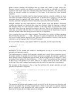
vertical axis moves from (0,0) down:
This starting origin is only the default coordinate system of the operating system.
Therefore, if you draw a shape with the following call, Ellipse(-100, -100, 100, 100), you
would get a circle whose center is positioned on the top-left corner of the screen. In this
case, only the lower-right 3/4 of the circle would be seen:
void CExoView::OnDraw(CDC* pDC)
{
CExoDoc* pDoc = GetDocument();
ASSERT_VALID(pDoc);
CPen PenBlue;
// Blue solid pen width = 1
PenBlue.CreatePen(PS_SOLID, 1, RGB(0, 12, 255));
CPen *pOld = pDC->SelectObject(&PenBlue);
pDC->Ellipse(-100, -100, 100, 100);
pDC->SelectObject(pOld);
}
Visual C++ and MFC Fundamentals Chapter 9: Strings
© FunctionX, Inc. 233
In the same way, you can draw any geometric or non-geometric figure you want, using
one of the CDC methods or creating functions of your choice. For example, the following
code draws a vertical and a horizontal lines that cross each other in the center middle of
the view:
void CExoView::OnDraw(CDC* pDC)
{
CExoDoc* pDoc = GetDocument();
ASSERT_VALID(pDoc);
CPen PenBlue;
CPen *pOld;
PenBlue.CreatePen(PS_SOLID, 1, RGB(0, 12, 255));
pOld = pDC->SelectObject(&PenBlue);
pDC->Ellipse(-100, -100, 100, 100);
CPen PenBlack;
PenBlack.CreatePen(PS_SOLID, 1, BLACK_PEN);
pOld = pDC->SelectObject(&PenBlack);
pDC->MoveTo(220, 0);
pDC->LineTo(220, 370);
pDC->MoveTo(0, 160);
pDC->LineTo(460, 160);
pDC->SelectObject(pOld);
}
Chapter 9 Strings Visual C++ and MFC Fundamentals
234 © FunctionX, Inc.
8.1.2 Changing the Coordinate System
As seen above, the default coordinate system has its origin set on the top-left section of
the screen. The horizontal axis moves positively from the origin to the right direction.
The vertical axis moves from the origin to the bottom direction. To illustrate this, we will
draw a circle with a radius whose center is at the origin (0, 0) with a radius of 50 units.
We will also draw a line from the origin (0, 0) to (100, 100):
void CExoView::OnDraw(CDC* pDC)
{
CExoDoc* pDoc = GetDocument();
ASSERT_VALID(pDoc);
// A circle whose center is at the origin (0, 0)
pDC->Ellipse(-50, -50, 50, 50);
// A line that starts at (0, 0) and ends at (100, 100)
pDC->MoveTo(0, 0);
pDC->LineTo(100, 100);
}
Visual C++ and MFC Fundamentals Chapter 9: Strings
© FunctionX, Inc. 235
This default origin is fine for most, if not all regular, operations performed on graphics
applications. Sometimes, you will need to control the position of the origin of the
coordinate system. For example, most CAD applications, including AutoCAD, allow the
user to set this origin.
The MFC library provides various functions to deal with the coordinates positions and
extents of the drawing area, including functions used to set the origin of the coordinate
system anywhere you want on the screen. Since you are drawing on a device context, all
you need to do is simply call the CDC::SetViewportOrg() method. It is overloaded with
two versions, which allow you to use either the X and the Y coordinates or a defined
point. The syntaxes of this method are:
SetViewportOrg(int X, int Y);
SetViewportOrg(CPoint Pt);
When calling this member function, simply specify where you want the new origin to be.
If using the second version, the argument can be a Win32 POINT structure or an MFC
CPoint class. To see the effect of this function, we will move the origin 200 units in the
positive direction of the X axis and 150 units in the positive direction of the vertical axis
without changing the circle and the line. Our OnDraw() method would look like this:
void CExoView::OnDraw(CDC* pDC)
{
CExoDoc* pDoc = GetDocument();
ASSERT_VALID(pDoc);
pDC->SetViewportOrg(200, 150);
// A circle whose center is at the origin (0, 0)
pDC->Ellipse(-50, -50, 50, 50);
// A line that starts at (0, 0) and ends at (100, 100)
pDC->MoveTo(0, 0);
pDC->LineTo(100, 100);
}