Cross Modulation in CDMA Mobile Phone Transceivers phần 1 pot
Bạn đang xem bản rút gọn của tài liệu. Xem và tải ngay bản đầy đủ của tài liệu tại đây (1.03 MB, 10 trang )
1
H
•
4/17/01
D
D
esign
esign
S
S
eminar
eminar
Agilent EEsof
Agilent EEsof
Customer Education
Customer Education
and Applications
and Applications
Part 1
Cross Modulation in CDMA Mobile Phone
Transceivers
2
H
•
4/17/01
Page 2
Rishi Mohindra
President and CEO
Adaptive RF, Inc.
736 S.Hillview Drive
Milpitas, CA95035,
USA
About the Author
Rishi Mohindra is the founding President & CEO of Adaptive RF, Inc. Prior to
that he was Principal Engineer, RF Systems, in Philips Semiconductors,
Business Line Interconnectivity. At Philips he was responsible for the
definition of architecture and IC specifications as well as the development, of
next generation transceiver chip sets, for WLAN and Wireless
Interconnectivity applications. He has earlier specified RF/IF ASICS for
CDMA/AMPS/TDMA Mobile Phones, and has also done extensive Systems
simulations for both RF ASICs and CDMA/AMPS/TDMA base band modems.
He has worked on the System design and definition of PWT, DECT and Pager
transceivers and the associated integrated circuits, and has also built various
RF transceivers for these applications. His other experience include IEEE
802.4 MAC implementation in software and the design of the digital modem.
He completed his Bachelors in Physics/Electronics in 1985 and Masters in
Electronic Engineering in 1990. In 1988 he was Manager R&D with
Microtechniques (India), a company for which he was also a consultant from
1984. Among the many products he developed there, a 16-line wireless remote
telephone subscriber system had wide spread deployment in India. He joined
Philips Semiconductors in 1990, located initially in The Netherlands, and
currently in Sunnyvale, USA. He has been granted 4 patents, and applied 15
more .
3
H
•
4/17/01
Page 3
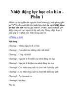
How to reduce phone size and battery
drain?
REDUCE INCREASE
LNA IP3 and
DUPLEXER ISOLATION
CROSS MOD
NOISE
•Smaller Duplexers
•Lower receiver LNA current
Lower TX-RX isolation
Lower IP3
Cross Modulation Noise
EXCEEDS
Thermal noise !
Transmitter leakage + Jammer
= Cross Modulation noise in Receiver
A basic IS-95 phone design challenge:
Cross Modulation in CDMA Mobile Phone Tranceivers
In a CDMA mobile phone, the transmitter and the receiver are operational
simultaneously, and connect to the antenna through a duplexer. Until recently,
the duplexers were very large in size and therefore provided sufficient
isolation of about 60 dB between the transmitter and receiver. However, with
reducing size of the handsets, especially in cellular/PCS dual-band and
CDMA/AMPS dual mode designs, the duplexers are also becoming smaller
and cheaper, at the expense of isolation between the transmitter and receiver
ports. For example, the PCS band duplexers have about 45 dB isolation, while
the cellular band duplexers have 45-50 dB isolation. The increased transmitter
leakage into the receiver is not generally a problem on its own, but when
combined with strong adjacent channel single tone jammers it poses a serious
design challenge for the linearity requirement of the receiver low noise front-
end RF amplifier (LNA). The time varying envelope of the transmitter
leakage signal can cause excessive cross modulation of the strong single tone
jammer largely due to the third order nonlinearity of the LNA.
4
H
•
4/17/01
Page 4
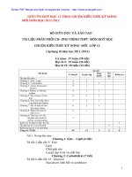
PTX
= 23 dBm
LTX
= 50 dB
LRX
= 3 dB
Prx
= -101 dBm
Pjam
= -30 dBm
PA
LNA
RX Band
Filter
Mixer
Time varying envelope
RECEIVER
TRANSMITTER
Cross Modulation in IS-95 CDMA Mobile Phone
The relevant transmitter and receiver blocks for the cross modulation are
depicted above, and the spectrum of the various signals are shown in the next
slide. The jammer is present just outside the edge of the channel filters, and
therefore a large part of the cross modulation signal power falls within the
channel filter pass band. If the IP3 of the LNA is not high enough, the cross
modulation signal power within the filter pass band can greatly exceed the
total thermal noise power.
The cross modulation phenomenon can also be viewed as a form of a time
varying gain compression of the LNA for the smaller jammer signal, by the
strong reverse link transmitter leakage signal that uses a non-constant envelope
modulation. The time varying gain compression of the LNA is called
desensitization of the single tone jammer. It results in AM modulation of the
single tone jammer. The cross modulation noise power is the total power in the
AM spectrum which is a around the single tone jammer. Keeping the cross
modulation power small can result in a large IP3 requirement for the LNA.
This design seminar shows the simulations and measurements done to
investigate cross modulation of the single tone jammer at the CDMA LNA
input, by the transmitter leakage into the receiver. Based on the simulations, a
Cross Modulation Noise model is developed to predict the IP3 requirements of
the receiver LNA. The simulation based model is compared with a theoretical
one.
5
H
•
4/17/01
Page 5
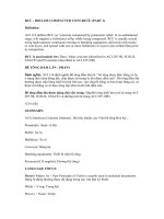
Received Signal
3rd order Cross
Modulation
Jammer Signal
Ptx = 23 dBm
(15 dBm in PCS)
Duplex Spacing = 45 MHz cellular
(80 MHz in PCS)
f
TX
Pjam= -30 dBm
f
RX
AM spectrum
Prx = -101 dBm
Transmitted
Signal
Signal Power & Spectrum
1-Tone Desensitization Test for CDMA Mobile Receiver
In the IS-95 CDMA 1-tone desensitization test, the Mobile Receiver is subject
to a single tone jammer that is 71 dB stronger than the wanted received signal,
which is at -101 dBm level. The wanted received signal is just 3 dB higher
than the minimum required sensitivity level of -104 dBm. Due to the power
control, the mobile's transmitter power is kept close to it's maximum level i.e.
23 dBm. The time varying desensitization of the LNA creates a weak AM
modulation in all of the received signals. The AM modulation is so weak that
it does not significantly affect the wanted signal to noise ratio i.e. the S/N of
the traffic, sync and the pilot channels after despreading. However, the effect
of AM modulation on strong adjacent channel interferers at the LNA input,
can be very severe. Under normal circumstances, these strong narrow band
AMPS interferers are completely removed by the channel filter before the
despreading occurs. With the weak AM modulation however, a small part of
the power of these interferers are spread over a 2.5 MHz band, centered around
the interfering signal itself. In the 1-tone desensitization test, these interferers
are 900 kHz (Cellular band) or 1.25 MHz (PCS band) away from the wanted
signal, and a considerable part of the 2.5 MHz band therefore over laps with
the received signal band, as sketched above. As the narrow band AMPS
interferer is 71 dB stronger than the received signal, there is a significant
interference power in the part of the 2.5 MHz band that over laps with the
received signal, resulting in considerable reduction in the signal to noise ratio
after despreading.
6
H
•
4/17/01
Page 6
• Both Jammer and TX leakage signals completely removed by RX
channel filters, and individually do not degrade Walsh channels S/N
after despreading.
• TX leakage of -23 dBm << Nominal RX out-of-band IP3 (about 0 dBm).
TX leakage produces very little desensitization of wanted RX signal.
• Only the combination of TX leakage and Jammer produces cross
modulation noise that can’t be filtered away, and imposes requirement
for high LNA IP3 and Duplexer Isolation.
Jammer and Transmitter Leakage
The transmitter induced LNA desensitization does not significantly
effect the IS-95 receiver sensitivity in the absence of jammers, and it
also does not effect the IS-95 receiver the dynamic range. However, as
stated earlier, it causes a major problem for the 1-tone desensitization
test, and thereby forces the use of highly linear LNAs which require very
high IP3 at the expense of large current. In comparison, the 2-tone
intermodulation tests for the CDMA mobile receiver are not as severe
as the desensitization test, because the power level of these 2-tone
interferers are much smaller (about 13 dB) compared with the 1-tone
jammer in the desensitization test, when the reverse link transmitter is
at its maximum level.
The image filter between the LNA and the mixer has about 30 dB
rejection at the transmitter frequency, and therefore the mixer is
sufficiently protected from cross modulation. The IP3 requirement for
this mixer is largly determined by the receive band 2-tone interference.
7
H
•
4/17/01
Page 7
Total Unwanted Signal at LNA input:
Receiver LNA 3rd order nonlinearity:
•1-tone jammer:
•Transmitter Leakage:
Unwanted signals at LNA receiver input:
Analysis of Cross Modulation
When a modulated and an unmodulated signal are present at the input
of a device (e.g. LNA) having 3rd order nonlinearity, then the
unmodulated signal gets a part of the modulation from the other signal,
at the output of the device.
The LNA nonlinearity and the input signals to the LNA are modeled
above.
The bottom equation is substituted in the top equation, and after
simplification, the terms are separated based on the frequencies. The
term with the frequency ω
j
is analysed further as it shows the cross
modulation on the jammer. This term is shown in the next slide.
8
H
•
4/17/01
Page 8
LNA output signal at jammer frequency:
Total Cross Modulation
Power:
Average Cross Modulation power:
Analysis of Cross Modulation (cont’d)
In the first equation above, the 1st and the 3rd terms within the brackets are
constants, and they only change the power of the unmodulated jammer signal.
The 3rd term shows the gain, and the 1st term shows the reduction in gain. The
middle term shows the cross modulation component. Only the envelope of the
modulated signal produces the cross modulation, while the phase θ(t) of the
modulated signal does not have any effect. The cross modulation noise power
is the power associated with this middle term. Referring it to the LNA input,
the time varying equivalent input cross modulation noise power (for the input
resistance R) is given in the next equation. The last equation gives the time
averaged total cross modulation power.
Only a part of the above cross modulation noise power falls into the pass band
of CDMA receiver channel filters. Simulations, which are described later,
show that for the Cellular band, the cross modulation noise power into the pass
band of CDMA receiver channel filters is 6 dB less than the one- sided power
i.e. 9 dB less than that given by bottom equation.
9
H
•
4/17/01
Page 9
Transmitter
Jammer
Nonlinear LNA
Output
Spectrum
TX Power
RX channel
Cross Modulation
noise power
Lowers out-of-band
noise floor
Cross Modulation simulation in ADS
The top level Cross Modulation simulation setup using the HP ADS
Communication System Designer is shown above. The attenuated
mobile transmitter signal is combined with a 1-tone jammer and fed
into a LNA. The LNA is modeled by a gain block having a third order
non-linearity. A 1.25 MHz wide band pass raised cosine filter at the
output of the LNA selects the total receive band noise due to cross
modulation. The cross modulation noise is measured by a power
meter that operates on the time domain samples of the signal
envelope at the filter output. This method is most accurate as it does
not involve power measurements from a spectrum (directly at the
LNA output) that usually suffers from spectral leakage effects.
However, the simulation runs slower because of the impulse
response time of the band pass filter. For a quick simulation, the LNA
output spectrum can be directly observed. The effects of spectral
leakage are considerably reduced by using a Hanning time window.
10
H
•
4/17/01
Page 10
• A TX-RX full duplex spacing of 45 MHz not required in simulation.
• Just 4-6 MHz spacing is sufficient. Ensure that spectral leakage (due to
simulation) of TX is much less than the cross modulation noise in the
RX channel.
• Sampling rate of 32 samples/chip used for a 6 MHz TX-RX spacing.
• Use extended IS-95 FIR filter impulse response to lower out-of-band
noise floor.
ADS Simulation
The simulation is done in the IQ modulation domain, and a pseudo-
carrier frequency does not have to be assigned in ADS when multiple
RF sources are used together, provided the sampling rate is large
enough to encompass the large frequency separation. The 1-tone
jammer is kept about 6 MHz away from the reverse link transmitter, and
is therefore considered a relatively very wide band modulated signal
requiring considerable over sampling. From the simulation
requirements, a Cellular full duplex spacing of 45 MHz is not required
between the reverse link transmitter and the one-tone jammer. With a 6
MHz spacing, the spectral leakage of the reverse link transmitter is
much lower than the cross modulation noise in the receive band.