DESALINATION, TRENDS AND TECHNOLOGIES Phần 3 ppt
Bạn đang xem bản rút gọn của tài liệu. Xem và tải ngay bản đầy đủ của tài liệu tại đây (6.18 MB, 35 trang )
Desalination of Coastal Karst Springs by Hydro-geologic, Hydro-technical and Adaptable Methods
59
color flowed out, that clearly differed from the blue sea. We observed a typical circle of
ground water flowing out of an estavelle at a distance about 0,5 km.
Prof. Ständer from Germany, who proposed the isolation of springs, answered in a letter
that a major development was achieved by the isolation of the springs area with the dam,
thereupon the salinity decreased to 200-300 mg/l CI. A second phase of the development
was completed with a rise of the pool level to 3 m ASL at a discharge of 12 m
3
/s and the
inflow of sea water stopped (Ständer, 1971). A photo shows a present outflow of ground
water outside the Kiveri dam (Lambrakis, 2005). The average springs discharge is 6 m
3
/s.
During the irrigation periods 1955-1990 the ground water quality worsened due to the over
pumping and the sea water intrusion (Monopolis et al., 1997; Tiniakos et al., 2005).
A short analysis of the available data indicates that the isolation of the Kiveri springs against
sea water inflow is not completed. A dam founded on much karstified breccia without a
consolidation of the limestone mass and without a grout curtain, is not a completed
structure. Prof. Ständer estimated the depth of the karstification at 90 m BSL. We suppose
this depth to be either 30 m deeper of the sea bottom at the estavelle observed in 1969, or 30
m deeper than a 120 m BSL deep sea level in the Pleistocene if the Argos bay is deep enough
(Breznik, 1998; Tiniakos et al., 2005).
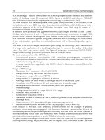
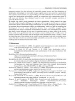
Fig. 19. Underground water connections of the Peloponnesus, found by tracing experiments
(Gospodarič & Leibungut, 1986).
Desalination, Trends and Technologies
60
We propose to prevent the sea water inflow by a grout curtain. The exploratory works
should be done in phases:
- First phase: boreholes drilled at a distance of 4 m along the crest of the dam and
grouted to a depth of 65 m BSL, then consolidation grouting of the karstified breccia
below the dam from 10 m to 35 m BSL.
- Second phase: boreholes, in between boreholes of the first phase, drilled and grouted till
130 m BSL.
- Third phase: grout curtain below the road extended for 100 and later 200 m on both
sides of the dam.
- Forth phase: additional grout curtains behind the smaller springs to the north if needed
and a higher rise of the pool’s level. In all this exploratory phases a testing with a rise-
spring-level to be made, the results analyzed and the next phases adjusted. A 4 m rise
enables the existing dam (Breznik, 1998).
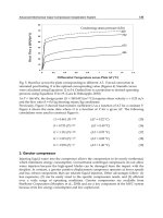
Fig. 20. Kivery dam. Desalination structures proposed (photo Breznik, 1969; Breznik, 1998;
Breznik & Steinman, 2008).
This is a general proposal for exploration activities and they should be adapted to the partial
results obtained. A final success with a 70% probability is to desalinate spring's water to 50
mg/l Cl
-
in dry periods, and a 90% probability in wet periods.
Desalination of Coastal Karst Springs by Hydro-geologic, Hydro-technical and Adaptable Methods
61
Legend:
1 - Marl-limestone –
Neogene
2 - Flysch
3 - Plated limestone –
Eocene
4 - Tripolitza limestone,
Mesozoic – Eocene
5 - Schists and
dolomites
Permian – Triassic
6 - Green rocks
7 - Fault scarps
8 - Anticline
9 – Polje
10 – Gorges
11 – Springs
1 - Flysch
2 - Plated limestone –
Eocene
3 - Tripolitza limestone
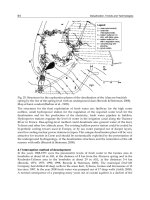
Fig. 21. Morpho-structural sketch of the Psiloritis massif and the Psiloritis-Anogia geological
section with Almyros Irakliou and Bali springs (Bonnefont, 1972).
Legend:
1 - Neogene – sand, clay
2 - Tripolitza series –
mostly limestone
3 - Metamorphic
schists –
quartzitic phyllite,
chlorite, marble
etc.
4 - Direction of flow
in veins during
the dry period
i - Almyros spring
v - Primary vein
r - Branching of
veins
s - Upper vein
m - Lower vein
m
min
- Lowest point of
the lower vein
u - Mouth of the
lower vein
f - Fault
gm - Sea level
Fig. 22. Almyros Irakliou spring in Greece. Schematic geological block diagram with the
supposed disposition of the spring veins in the conduit-flow karstic aquifer (Breznik, 1978).
Desalination, Trends and Technologies
62
4.5 Almyros Irakliou brackish spring in Greece
The characteristic of this spring, at 1 km from the sea coast, with many primary veins, of a
300 km
2
karstic recharge area and with very deep vein-branchings at differed depths, is a
very slow increase of the salinity during a decrease of the discharge (Ré, 1968; Fig. 6;
Breznik, 1971; 1973; 1998; Breznik & Steinman, 2008; Monopolis et al., 2005; Panagopoulos,
2005; Soulios, 1989).
All the veins are in Mesozoic limestone and the lower veins below the Festos-Irakliou
graben filled with Neogene deposits. This spring was investigated by the United Nations -
UNDP-FAO and Greek Government in the years 1967-1972. Between the spring and sea
coast 15 deep boreholes, with a mean depth of 240 m, were drilled, with the aim to find, and
to seal with a grout curtain, a conduit with sea water inflow. The result of investigation was
that this conduit is not between the nearest sea and the spring, but is below Neogene
deposits at about 800 m BSL and about 14 km long.
Almyros spring has a mean discharge of 8 m
3
/s, a temperature of water 16° C and had a
tritium content of 45 T. U. of samples taken in August 1969, analyzed at IAEA in Vienna.
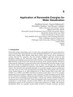
Fig. 23. Almyros Irakliou brackish spring. Main aquifers of the Psiloritis and Keri massifs
and of the Irakliou graben (Breznik, 1984; 1998).
Precipitations at Rhodos island had 1100 T.U. in 1963, 200 T.U. in 1964 and 50 T.U. in 1969,
while in Ljubljana 120 T.U. in 1975, what confirms a large volume of the Psiloritis
underground storage and a slow, many years lasting outflow of precipitations. A week
aquifer in Neogene deposits had a discharge of 0,12 m
3
/s, a temperature of water 19-20° C
and 19-13 T. U. in the same period (Breznik, 1971).
We proposed to explore the desalination of the Almyros spring by the isolation, rise-spring-
level and interception methods. A 10 m rise of spring level was proposed (Breznik, 1971). A
new dam was constructed (1976) and spring level was raised at 10 m ASL for some month in
1977 and 1987. Spring water remained brackish (negative result) but the discharge
diminished only slightly and no estavelles appeared in the Irakliou Sea (positive results).
We concluded that a higher elevation of the level should be determined by a winter test
with a larger discharge of water (Breznik, 1978), proposed a 20 to 30 m rise (Breznik, 1984)
and calculated a 28,76 m, however with uncertain data (Breznik, 1989).
Desalination of Coastal Karst Springs by Hydro-geologic, Hydro-technical and Adaptable Methods
63
4.6 Rise-spring-level method of the development
This method requires a siphon shaped lower vein. Almyros has indeed a very deep lower
vein, formed by a gradual subsidence of the Festos-Irakliou graben. We propose a 25 to 35 m
ASL spring level with a construction of an underground dam.
The exploration phases with testing are: First phase: excavate a shaft, of 8 m diameter, with
reinforced concrete lining, from surface to 5 m ASL with 2 table valves; drill interception
wells into the main karst conduit till 30 m BSL; excavate 2 bottom outlets, of 5 m
2
with
reinforced concrete lining, with valves at the outlets; seal the conduit with a concrete plug
and a consolidation grouting. Raise the spring level, register the salinity and locate water
losses. Second phase: construct a grout curtain of one row boreholes at a 4 m distance, till a
depth of 80 m BSL. Raise the spring level and register the results. Third and other phases:
condense and extain the grout curtain, with boreholes at 2 m distance, till a depth of 120 m
BSL, construct a small dam around an expected overflow karst spring in the Keri ravine.
Raise the spring level to 25-35 m ASL. When the salinity is below 50 mg/l CI and losses of
water are small the exploration phases are completed. We expect, with an 80% probability, a
safe yield of fresh water of about 2 m
3
/s in dry periods and a 90% probability of fresh water
in wet periods.
Fig. 24. View of the Almyros Irakliou spring area (photo Breznik, 1970).
The main object of the underground dam is the concrete plug with grouting (No. 5 in Fig.
25). The ground water flow through the place of the proposed plug could be blocked, by
diverting the flow through the extended bottom outlet (No. 3), bellow the 1976 dam. This is
achieved by raising the water level of the spring pool to about 6 m ASL, by regulating the
water valves of the 1976 dam. Down flow of the fresh concrete into the steep main karst
conduit (No. 1), could be prevented by a downside planking of the plug.
The first possibility is a planking of closely drilled boreholes of 60 m depth, of 30 cm
diameter with casing filled with concrete. Two to three additional boreholes with pipes will
enable pumping of concrete from the surface.
The second possibility is a new access shaft of 3 m diameter and 45 m depth at a 10 m
distance upstream from the plug. Divers have to construct steel planking and install pipes
for pumping concrete from a surface to a depth of about 25 m below water level.
Constructors could propose other solutions.
Desalination, Trends and Technologies
64
Fig. 25. Structures for the exploration phases of the desalination of the Almyros brackish
spring by the rise of the spring level with an underground dam (Breznik & Steinman, 2008).
Map of karst conduit (Barbier et al., 1992).
The structures for the final exploitation of fresh water are: Spillway for the high water
outflow, small hydropower station for the regulation of the required water level for the
desalination and for the production of the electricity, fresh water pipeline to Iraklion.
Hydropower stations regulate the level of water in the irrigation canal along the Durance
River in France. Rise-spring-level method could desalinate also ground water of the Keri,
Tylissos and other low altitude areas. The existing Iraklion power station could be cooled by
hyperbolic cooling towers used in Europe, or by sea water pumped out of deeper layers,
used for cooling nuclear power stations in Japan. This unique desalination plant will be very
attractive for tourists in Crete and should be economically exploited by the presentation of
the underground hydrogeology, of the desalination structures and the restoration of the old
scenery with mills (Breznik & Steinman, 2008).
4.7 Interception method of development
In the years 1968-1971 were the piezometric levels of fresh water in the Gonies area in
boreholes at about 44 m ASL at the distance of 8 km from the Almyros spring and in the
Koubedes-Tylissos area in the boreholes at about 29 m ASL, at the distances 3-4 km
(Breznik, 1971; 1973; 1990; 1998; Breznik & Steinman, 2008). The municipal DAYAH
Company had drilled 40 deep wells in the areas Keri, Tylissos, Gonies and Krousonas at 13
km since 1987. In the year 2000 fresh water was pumped out of 17 deep wells (Arfib, 2000).
A normal consequence of a pumping many years out of coastal aquifers is a decline of the
Desalination of Coastal Karst Springs by Hydro-geologic, Hydro-technical and Adaptable Methods
65
piezometric surface and the inflow of sea water. In Tylissos area the piezometric surface
declined from about 29 m in seventies to about 15 m in 1997 and induced a salination of
wells (Monopolis et al., 1997; 2005).
The important question is now; could water of wells in the Gonies and Krousonas areas
remain fresh? Ground water of these areas flows to Almyros spring through a very deep
vein-branching at 800-1000 m BSL, where is a fresh water outflow and a sea water inflow
which depends upon the piezometric surface of fresh water. An expected overpumping of
the Gonies-Krousonas wells, due to the loss of the Keri-Tylissos salinated wells, will lower
the fresh water piezometric surface and induce a sea water inflow. Only moderate pumping
yields could prevent the salination of this water. An over pumping of Malia wells will have
similar consequences (Breznik & Steinman, 2008).
5. Conclusions and recommendations
Many desalination methods were proposed and many scientific papers published but, the
important Greek springs: Bali, Kiveri and Almyros Irakliou, are still brackish after 30 years
of attempts. In a karst underground are so many unknown data, needed for a mathematical
ground water model, that the results are not reliable. We propose to achieve the desalination
with physical-field tests: by the isolation method for the Bali and Kiveri springs with grout
curtains and by the rise-spring-level method for the Almyros Irakliou spring with an
underground dam. We estimate there are 70-80 % probabilities of the success in dry periods
and 95% for Bali and Kiveri and 90% for Almyros Irakliou springs in wet periods.
The Dragonja river storage reservoir with 20 - 30 millions m
3
of fresh water pumped out of
Rižana river, could solve water shortage of SW Slovenia. The Intergovernmental Panel on
Climate Change (IPCC) warns about still smaller precipitations and higher temperatures in
the Southern Europe in the future. So, the supply of fresh water will become increasingly
important.
The proposed methods are intended to intercept fresh water before it is mixed with salt
water, allowing the accumulation of water in wet seasons. No doubt, proposed solutions
require greater initial investment, but have low operating costs. Besides, water supply is not
exposed to the imported high-technology and is not high energy demanding.
We reserve author's rights for the proposed desalination methods and structures (Breznik,
1998; Breznik & Steinman, 2008).
6. Glossary
Admissible salinity: The quantity of salts in drinking or irrigation water which is harmless
to people, animals or vegetation. Slovene and other countries' standards for
drinking water is 250 mg/l of Cl
-
. In dry areas drinking water with 500 mg/l of Cl
-
is considered as harmless. Many villages in the Mediterranean area use water with
more than 500 mg/l of Cl
-
, the Bedouins of the Sahara up to 2000 mg/l of Cl
-
.
Aerated zone: Zone above ground water surface in which karstic pores are filled partially
with air and partially with water.
Aquifer: A formation, group of formations or part of a formation that bears water which is
not bound chemically or physically to the rock.
Brackish spring: General term which means a spring with brackish water but also the vein
and a place of such a spring.
Desalination, Trends and Technologies
66
Brackish water zone (also called zone-of-mixing or transition zone): Part of aquifer saturated
with brackish water.
Doline: A depression that has a funnel-shaped hollow with a diameter of 10 to 100 m,
formed by the dissolving of limestone or dolomite. It is an international term. The
local term is vrtača, the English term being sinkhole.
Drowned zone: Zone below ground water surface in which karstic pores are saturated with
water.
Equilibrium plane: Nominal plane in a karst of anisotropic permeability connecting those
points of veins and branchings where the water pressures from fresh water and sea
water sides are equal.
Fresh water zone: Part of aquifer saturated with fresh water.
Interface: The surface bordering the fresh water and sea water in an aquifer of isotropic
permeability. This border could be sharply defined but is usually a transition zone.
Karst aquifer of anisotropic permeability: Karst region with isolated karstified zones with
unkarstified blocks between them. Ground water moves along veins or conduits,
which means along well-karstified zones. The aquifer is highly permeable in the
direction of veins, but poorly permeable or impermeable in the transverse direction.
Ground water movement is similar to the movement of water in a system of pipes
which are not densely disposed, known as 'conduit type circulation'.
Karst aquifer of isotropic permeability: Karst region with many solution fissures, small
channels which are all well connected in all directions. Movement of water is
possible in all directions and is analogous to the ground water movement in
granular sediments, known as 'diffused type circulation'.
Karstic ground water, karst aquifer: Water which fills karstic pores and veins in the
drowned zone and is not bound physically or chemically to the rock.
Polje: An international term that refers to the largest karst hollow with a flat floored linear
depression. In its typical form it has a steep side and steep circumference.
Ponor: This is the largest entry in the base or in the side of the polje in which water flows, an
international term. Schwinde (Ger), swallow hole (Eng) and perte (Fr).
Salinity: Quantity of salts in water. In this paper expressed as content of chlorine ions (Cl
-
) in
mg/l. The salinity of the Mediterranean Sea is about 21000 mg/l of Cl
-
.
Sea estavelle: A submarine spring with fresh water which ceases to flow in each dry season
and starts to swallow sea water.
Sea ponor: Hole in the sea bottom or seashore which swallows sea water.
Sea water zone: Part of aquifer saturated with sea water.
Storage coefficient of the karst is the volume of water which a karstic aquifer releases from
storage or takes into storage.
Submarine spring: A spring with either fresh or brackish water rising from the sea bottom.
Uvala: A coalescence of two or three dolines, an international term.
Vein or conduit: General term for a zone which is highly permeable in the flow direction
and poorly permeable or impervious in the transverse direction. Ground water
moves through veins in a karst of anisotropic permeability. The form of the vein is
undefined; it could be a solution channel, a permeable fissured zone, a system of
small connected cavities, etc.
Vein-branching or branching: The place where the primary vein branches off into a lower
vein, connected with the sea, and an upper vein, leading to the spring.
Desalination of Coastal Karst Springs by Hydro-geologic, Hydro-technical and Adaptable Methods
67
7. Acknowledgments
We thank the Governments of Slovenia, Croatia, Montenegro, Greece and Turkey for the
presentation of their unpublished investigation results.
8. References
Arandjelović, D. (1976). Geofizika na karstu, Geozavod Beograd, Beograd.
Arfib, B.; de Marsily, G. & Ganoulis, J. (2000). Pollution by seawater intrusion into a karst
system: New research in the case of the Almyros source (Heraklio, Crete, Greece).
Acta carsologica, Vol. 29, No. 1, pp. 15-31, ISSN 0583-6050.
Arfib, B. & Bonacci, O. (2005). Particular aspects of discharge in coastal karstic aquifers, In:
Groundwater management of coastal karstic aquifers (EUR 21366 En, COST Action 621,
Final Report, Part II), Tulipano, L.; Fidelibus, M.D. & Panagopoulos, A. (Ed.), pp. 87–
104, Office for Off. Publ. of the EC, ISBN 92-898-0002-X, Luxembourg.
Barbier, J. L.; Therond, R. & Paloc, H. (1992). Source d’Almyros d’Heraklion, Synthese des
etudes depuis 1988, Rapport general, Unpublished report of GERSAR to the Greek
Ministry of Agriculture, pp. 65, Paris.
Bidovec, F. (1965). The hydrosystem of karstic springs in the Timavo basin, UNESCO – IHD
Symposium on Hydrology of Fractured Rocks, pp. 263-274, Dubrovnik, October 1965,
UNESCO, Paris.
Biondić, B. (1988). Tapping and protection of underground water in the Adriatic region
related to the new conception of the structure of Dinarides. In: Proceedings of the
IAH 21
st
Congress, Guilin, China, Daoxian, Y., (Ed.), pp. 187-193, Guilin, China.
Biondić, B.; Gunay, G.; Marinos, P.; Panagopoulus, A.; Potié, L.; Sappa, G. & Stefanon, A.
(2005). Protection and remediation practices, In: Groundwater management of coastal
karstic aquifers (EUR 21366 En, COST Action 621, Final Report, Part II), Tulipano, L.;
Fidelibus, M.D. & Panagopoulos, A. (Ed.), pp. 231-241, Office for Official
Publications of the European Community, ISBN 92-898-0002-X, Luxembourg.
Boegan, E. (1906). Le sorgenti d’Aurisina. Rassegna bimestrale della Societa Alpine delle
Giulie. Trieste.
Bonacci, O. (1987). Karst Hydrology with Special Reference to the Dinaric Karst, Springer Verlag,
Berlin.
Bonnefont, J.C. (1972). La Crete, etude morphologique, Ph. D. Thesis, Paris, University of
Paris IV.
Bonifay, E. (1974) in Potie, L. & Ricour, J. 1974. Etude et capitage de résurgences d éau douce
sous - marines. – Ressources en Eau, pp. 5-27, Paris.
Borelli, M. & Pavlin, B. (1965). On the underground water leakage from the storages in Karst
region. Karst storages Buško blato, Peruća and Kruščica, UNESCO – IHD
Symposium on Hydrology of Fractured Rocks, pp. 32-63, Dubrovnik, October 1965,
UNESCO, Paris.
Bosi et al. (1996). Eustatic curve related to Quaternary and curve of max regressions. - EUR
21366 En, COST Action 621, p. 165, Brussels.
Božičević, S. (1976). Losses of Grout in Caves, 1
st
Yugoslavian Symposium of Soil Conservation,
pp. 17-23, Zagreb, 1976.
Breznik, M. (1961). Akumulacija na Cerkniškem in Planinskem polju (Water accumulation in
the Cerknica and Planina polje.), Geologija, Vol. 7, pp. 119-149, ISSN 0016-7789.
Desalination, Trends and Technologies
68
Breznik, M. (1971). Geology and Hydrogeology of the Almyros spring area, Unpublished note
No. 103 of UNDP – FAO, presented to Greek Gov., pp. 1-94, Iraklion.
Breznik, M. (1973). Nastanek zaslanjenih kraških izvirov in njihova sanacija (The Origin of
Brackish Karstic Springs and their Development; Summary of the Doctor of
Geology Thesis, 1972), Geologija, Vol. 16, pp. 83-186, ISSN 0016-7789.
Breznik, M. (1976). Mogućnost saniranja zaslajenih kraških izvora sa injektiranjem
(Possibility of Development of Brackish Karstic Springs by Grouting), 1
st
Yugoslavian Symposium of Soil Conservation, pp. 293-296, Zagreb, 1976.
Breznik, M. (1977a). Exploration and Development of Coastal and Submarine Brackish
Springs in Turkey, Unpublished report of UN-OTC presented to Turkish Government,
pp. 1-35, Ankara.
Breznik, M. (1977b). Test to Raise the Water-level of the Almyros Irakliou Spring -
Evaluation of Results of the 1977 Summer Test, Unpublished report presented to Greek
Gov., pp. 1-11, Iraklion.
Breznik, M. (1978). Mechanism and Development of the Brackish Spring Almyros Irakliou.
Ann. Geol. Des Pays Hell., pp. 29-46, Athens.
Breznik, M. (1979). The Reliability of and Damage to Underground Dams and Other Cut off
Structures in Karstic Regions, 13
th
International Congress on Large Dams, pp. 57-79,
ISBN, New Delhi, Paris.
Breznik, M. (1981). Groundwater hydrology and hydraulics – Flow in aquifiers. International
course: Water resources engineering, pp. 1-54, Beograd.
Breznik, M. (1984a). Bansagar project – Protection of Kuteshwar limestone deposit,
Unpublished report presented to the Central Water Commission of Government of India,
pp. 1-15, New Delhi.
Breznik, M. (1984b). Development of the Almyros Irakliou brackish spring, Unpublished
report presented to the Greek Government, pp. 1-34, Ljubljana.
Breznik, M. (1984c). Exploration of the Bali brackish spring, Unpublished report presented to the
Greek Government, pp. 1-5, Malia.
Breznik, M. (1985a). Exploration, design and construction of cut offs in karstic regions, 15
th
International Congress on Large Dams, pp. 1111-1129, Lausanne, 1985, Paris.
Breznik, M. (1985b). Neka iskustva o bušenju bunara u krasu (Some experiences on drilling
wells in the karst, in Serbo-Croatian), Conference ‘Voda i krš’, pp. 159-164, Mostar.
Breznik, M. (1985c). Perspektiva in problematika izkoriščanja podzemnih voda. (Perspective
and problematics of ground water exploitation, in Slovene), Acta hydrotechnica, Vol.
3, Special edition [1], pp. 1-45, ISSN 0352-3551.
Breznik, M. (1989). Explorations, mechanism and development of brackish karst spring
Almyros toy Irakleioy, Unpublished report presented to the Greek Ministries of Agriculture
and Research and Technology and Universities of Athens and Crete, pp. 1- 59, Ljubljana.
Breznik, M. (1990a). Development of Brackish Karstic Spring Almyros in Greece. Geologija,
Vol. 31/32, pp. 555-576, ISSN 0016-7789.
Breznik, M. (1993). Evaluation of exploration results and development possibilities by
underground dam and other methods of karst spring Almyros Irakliou,
Unpublished report presented to the Greek Gov., Eastern Crete Development
Organisation, pp. 1-90, Ljubljana.
Breznik, M. (1996). Vodni viri za Obalo in Kras Slovenije (Water sources of Coastal Region and
Slovenian Karst, in Slovene), UL-FGG, Ljubljana.
Breznik, M. (1998). Storage reservoirs and deep wells in karst regions, A.A. Balkema, ISBN
9789054106883, Rotterdam/Brookfield.
Desalination of Coastal Karst Springs by Hydro-geologic, Hydro-technical and Adaptable Methods
69
Breznik, M. (2005). Vodni viri Slovenske Istre (Water sources of Slovene Istria, in Slovene),
Unpublished report to the Ministry for Environment and Physical Planning, pp. 1-
35, Ljubljana.
Breznik, M. & Steinman, F. (2008). Hydromechanism and desalination of coastal karst aquifers:
Theory and cases. Acta carsologica, Vol. 37, No. 2-3, pp. 197-209, ISSN 0583-6050.
Doctor, D.; Lojen, S. & Horvat, M. (2000). A stable isotope investigations of the classical
Karst aquifer: Evaluating karst groundwater components for water quality
preservation. Acta carsologica Vol. 29, No. 1, pp. 79-92.
Economopoulos, P. (1983 and 1989). Situation of estavelles and coastal spring in Bali bay,
scale 1:25000, Unpublished map, photo, written communications to Breznik.
Ghyben-Badon, W. (1888-1889). Nota in verband met de voorgenomen putboring nabij
Amsterdam. - Tijdschrift van het Koninklijk Institut van Ingenieurs, Hague. 27 pp.
Gjurašin, K. (1943). Prilog hidrografiji primorskog krša. Tehnički vjesnik, Vol. 60, No. 1-2, pp. 1-17,
Zagreb.
Glanz, T. (1965). Das Phaenomen der Meermuhlen von Argostolion. Steirische Beitrage zur
Hydrogeologie, Vol. 17, pp. 113-127, Graz.
Gospodaric, R. & Leibungut, C. (1986). Evaluation and Interpretation of the Tracing data, In:
Hydrogeology of the Eastern Pele-ponissos, Greece, Morphia, A. & Zojer, A. (Ed.), pp.
100-110, 5
th
Int. Symposium on Underground Water Tracing, New York.
Herzberg, A. (1901). Die Wasserversorgung einiger Nordseebader. Zeitung für
Gasbeleuchtung und Wasserversorgung, Vol. 44, pp. 815-819.
Kajfež-Bogataj, L. (2006). Glede spreminjanja podnebja Slovenija ni izjema (in Slovene).
Proteus, Vol. 69, No. 2, pp. 54-61.
Kajfež-Bogataj, L. (2007). Poročili, ki spreminjata poglede na podnebne spremembe.
Pentagon and Stern reports (in Slovene). Proteus, Vol. 69, No. 7, pp. 294-302.
Kohout, F. A. (1966). Submarine Springs. A neglected Phenomenon of Coastal Hydrology,
Symposium on Hydrology and Water Resources, ISBN, Ankara, 1966.
Komatina, M. (1975). Hidrogeološke oblike slivova centralnodinarskog karsta, Rasprave
Zavoda za geološka i geofizička istraživanja, Vol. 16, pp. 1-105, Beograd.
Krivic, P. (1982). Naravna nihanja gladine podtalnice kraskega vodonosnika (Variations
naturelles de niveau piezometrique d’ un aquiffére karstique.), Geologija, Vol. 25,
No. 1, pp. 129-150, ISSN 0016-7789.
Krivic, P. & F. Drobne. (1980). Hidrogeološke raziskave Tržasko - Komenskega krasa,
(Hydrogeologische Untersuchungen des Karstes von Trieste und Komen), 6
th
Yugoslavian Symposium Of Hydrogeology and Engineering Geology, pp. 233-239,
Portorož, 1980, Yugoslavia.
Kuščer, I. (1950). Kraški izviri ob morski obali (Karst Sources at the Sea Coast, in Slovene),
Dissertationes Academia Scientarium et Artium Slovenica, Vol. 3, No. 1, pp. 97-147.
Kuščer, I. & Kuščer, D. (1962). Observations of Brackish Karst Sources and Swallowholes in
the Yougoslav Coast. - Mem. de l’ Ass. Intern. Des Hydrogeologues. V. Reunion
d’Athens.
Lambrakis, N. (2005). Kiveri coastal springs, Greece. - EUR 21366 En, COST Action 621, p.
262, Brussels.
Maurin, V. & Zoetl, J. (1965). Salt Water Encroachment in the Low Altitude Karst Water
Horizons of the Islands of Kephallinia. In: Dubrovnik Symposium, AISH-UNESCO,
pp. 423-438.
Monopolis, D.; Lambrakis, N. & Perleros, B. (2005). The brackish karstic spring of Almiros of
Heraklion, In: Groundwater management of coastal karstic aquifers (EUR 21366 En,
Desalination, Trends and Technologies
70
COST Action 621, Final Report, Part II), Tulipano, L.; Fidelibus, M.D. &
Panagopoulos, A. (Ed.), pp. 321-328, Office for Off. Publ. of the Europ. Commun.,
ISBN 92-898-0002-X, Luxembourg.
Mueller, I. & Schotterer, U. (1986). Electromagnetic VLF Resistivity Prospection in the
Region of Tripolis and the Coastal area of Argos – Astros, 5th International
Symposium of Underground Water Tracing, pp. 425–440, Athens, 1986.
Nonveiller, E. (1989). Grouting Theory and Practice, Elsevier, ISBN 0444874003, Amsterdam.
Panagopoulos, A. (2005). Almiros spring, Heraklion, Greece. - EUR 21366 En, COST Action
621, p. 258, Brussels.
Pavlin, B. (1990). Yugoslav littoral belt karst springs used for water supply, 6
th
International
Congress of International Association for Engineering Geology, pp. 1387-1394, ISBN 90
5410 130 3, Amsterdam, 1990, Balkema, Rotterdam.
Petrič, M. (2005). Klariči, Brestovica, Slovenia. - EUR 21366 En, COST Action 621, p. 264,
Brussels.
Potie, L. & Ricour, J. (1974). Etudes et captage de résurgences d’eau douce sous-marines
(Studies and Capture of Resurgences of Submarine Freshwater), Ressources en eau,
pp. 5-26.
Ré, R. & Breznik, M. (1968). The problems of the Almyros spring of Iraklion, Unpublished
note No. 2 of UNDP – FAO, presented to Greek Government, pp. 1-114, Iraklion.
Rošker, J. (2007). Živimo v najtoplejši dobi v zadnjih 150 tisoč letih (in Slovene), Polet,
supplement of Delo, 05.04.2007, pp. 10-13, ISSN 1580-8041.
Soulios, G. (1987). System karstique aquifére d’Almyros, Iraklion, un case interessant de
functionement de systéme littorale, Bull. Centre d’Hydrogeol., Vol. 7, pp. 169-191.
Steinman, F.; Gosar, L. & Banovec, P. (2004). Preparation of Sensitivity Maps of the
Slovenian Coast, Final report, CAMP Slovenia, pp. 1-24 & maps.
Steinman, F.; Kozelj, D. & Banovec, P. (2006). Regional Water Supply in State Development
Plan (in Slovene). - Slovenian Water Protection Association - Proceedings I, 24-32,
Portorož.
Steinman, F. et al., (2007). Expert group assessment of the project: Drinking Water Supply of
the Slovenian Istra and Karst hinterland, Unpublished Report to the Ministry of
Environment and Physical Planning (in Slovene), pp. 1-64, Ljubljana.
Ständer, W. (1971): written answer to Breznik.
Šegota, A. (1986). Surface of the Adriatic Sea throughout the last glacial period with part of
the present Adriatic Sea emerged as dry land 25.000 years ago. - EUR 21366 En,
COST Action 621, p. 116, Brussels.
Thérond, R. (1973). Recherche sur l’étancheité des lacs des barrages en pays karstiques, Eyrolles,
ISBN 978-2-212-01550-8, Paris.
Tiniakos, L.; Tavitian, J. & Livaniou-Tianikou, A. (2005). The Anavalos-Kiveri coastal spring
(Argolis, E. Peloponnesus, Greece): Hydrogeology and drought-water quality
relation, In: Groundwater management of coastal karstic aquifers (EUR 21366 En, COST
Action 621, Final Report, Part II), Tulipano, L.; Fidelibus, M.D. & Panagopoulos, A.
(Ed.), pp. 312-320, Office for Off. Publ. of the Europ. Commun., ISBN 92-898-0002-
X, Luxembourg.
Vlahović, V. (1981). Kraška akumulacija Slano (Karstic accumulation in Slano), Črnogorska
akademija nauka i umjetnosti (The Montenegrian Academy of Sciences and Arts, in
Serbian), Podgorica.
4
Corrosion Control in the Desalination Industry
Michael Schorr
1
, Benjamín Valdez
1
, Juan Ocampo
2
and Amir Eliezer
3
1
Instituto de Ingeniería, Departamento de Materiales, Minerales y Corrosión, Universidad
Autónoma de Baja California, México, Blvd. Benito Juárez S/N, CP. 21900,
Mexicali, Baja California,
2
Facultad de Ingeniería Mexicali, Universidad Autónoma de Baja California,
México, Blvd. Benito Juárez S/N, CP. 21900, Mexicali, Baja California,
3
Sami Shamoon College of Engineering Corrosion Research Center, Ber Sheva ,
1,2
México
3
Israel
1. Introduction
The environment quality, worldwide water scarcity and clean energy have been established
today as central disciplines in modern science, engineering and technology. They are
already being linked to the crucial, actual problems of climate change, global warming and
greenhouse-gas emissions, all interrelated phenomena (Valdez & Schorr, 2010). Innovative
desalination technology of saline water (SW) contributes to alleviate these problems by
producing abundant fresh water, from SW, mainly seawater and brackish water (I.D.E
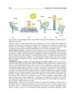
Technologies, 2004; Charash et al, 1991).
Desalination plants (DPs) have a high level of corrosion risk since they handle and process
aggressive SW under severe operating conditions which include filtration, heat exchange,
distillation, evaporation, agitation and circulation and high flow velocities, often turbulent.
These SW: sea, brackish and brines cause localized corrosion such as pitting, crevice,
galvanic and stress corrosion. In addition, biological fouling and mineral scaling are
frequent nuisances that alter the equipment surface performance and induce corrosion
(Malik, 2000).
Desalination has been practiced since ancient times for providing drinking water on
seafaring ships, using solar or fuel heat for distillation. Aristotle, the Greek philosophic
scientist (384-322 B.C.) mentions desalting seawater with solar energy. Natural gas was used
as fuel in ancient China to evaporate water from salt brine.
Moses, the prophet, wandering through the Sinai Desert found water that the people could
not drink because it was bitter. Then, Moses threw a piece of wood into the water and the
water become sweet (Exodus 15:22-25). Perhaps, these are some antique practices on water
treatment, their details lost through the eons…
Public water supplies are recorded in the Bible: Genesis 26, II Kings 20:20, John 4;
community wells and water works where built by the Hebrews, Egyptians, Mesopotamians,
Phoenicians, Persians, Greeks and Romans, including canals, aqueducts, reservoirs,
distribution pipes and flood-control facilities.
Desalination, Trends and Technologies
72
Desalination is not a new technology; in 1790 the US Government received a proposal to
install a distillation method to convert salt water to fresh water. In 1952 the US Congress
passed “The Saline Water Act” to provide federal support for desalination, as a new mean
for supplementing long deficient supplies of fresh water.
Use of suitable corrosion resistance alloys (CRAs): titanium, stainless steels (SS), Ni-base
alloys, Cu –Ni alloys and Al-Mg alloys is the most direct means of preventing corrosion.
Corrosion resistance is the main property to be considered in the choice of materials for
plant equipment. Today about 15,000 DPs operate worldwide with an estimated total
production capacity of 32 million m
3
/day, in the Mediterranean Sea coast countries, the
Middle East, South America deserts, the Canary and Caribbean islands; all places with
limited water supplies. In the USA there are 1,500 desalination facilities constituting a 30b
USD business which is expected to double in capacity by 2016. A limited number of DPs
have been built on the California coast, primarily because of desalination cost is generally
higher than the cost of other water supply alternatives, however, as drought conditions
occurs desalination large projects are being planned, e.g., the Carlsbad project.
The world largest plant in Saudi Arabia produces 1 Mm
3
/day. An advanced seawater DP
was installed in 2005 in Ashkelon, Israel with a capacity of 100 Mm
3
/year. It is operated by
IDE Technologies; uses Seawater Reverse Osmosis (SWRO) technology and employs state-
of-the-art means for recovery of energy from independent, combined cycle electricity
station, with a capacity of 80 MW (Kronenberg, 2004).
1.1 Water resources
There is an almost unfathomable amount of water on earth: about 1.4 billion km
3
(330
million cubic miles), (Barlow and Clark, 2002). Of this total, less than 3% is fresh water
(about 35,000,000 km
3
), much of which (about 24,000,000 km
3
) is inaccessible due to the fact
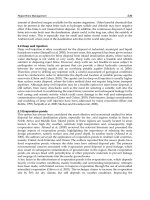
that it is frozen in ice caps and glaciers (Figure 1). It is estimated that just 0.77% (about
11,000,000 km
3
) of all the earth’s water is held as groundwater, surface water (in lakes,
swamps, rivers, etc.) and in plants and the atmosphere (Shiklomanov, 1993).
2. The desalination industry
Due to an increased population growth and the expectation of high living standards, the
demand for water and electricity in the desertic and arid regions of the world is soaring.
Placing DPs combined with power generating units allows the heat extracted from the
process to evaporate seawater. Desalination is the most viable solution to the 21th century´s
shortage of fresh water for human consumption and irrigation obtained from sources of SW
(Kowitt, 2009).
The desalination industry is in the middle of an expansion and modernization program
designed to construct more efficient and larger DP’s, that will reduce production costs. The
maintenance of its infrastructure assets requires a robust understanding of the integration
between global climate change and the materials engineering-structure-climate-interaction,
induced by variations in humidity, temperature, solar radiation, drought and pluvial
precipitation mainly during extreme events (Valdez & Schorr, 2010). Recently the Institute of
Materials, Minerals and Mining (IOM3), London has published a special issue of its journal
which brings together papers examining climate change induced corrosion (Valdez &
Schorr, editors 2010; Roberge, 2010).
Corrosion Control in the Desalination Industry
73
Fig. 1. Distribution of world water
This industry is based on the principles and practices of water chemistry, chemical
engineering and efficient energy management. The most widely utilized technologies are
thermal and membrane but solar “green” energy is applied, without relying on fossil fuels:
oil, gas and coal.
Actual innovation desalination technology is less energy-consuming and more
environmentally friendly. DP’s require varied engineering materials, structures,
installations, equipment and machinery that should function with industrial efficiency and
labor safety to assure its economic performance.
The economic and social relevance of the desalination industry is evident by the activities of
the diverse international and national professional associations, R&D institutions and
industrial enterprises involved in all the aspects of desalination science, engineering and
technology (Table 1). It includes authorities from government, industry, and academia that
address progress of vital importance for the national and global prosperity.
Lately, the threat of bioterrorism, have pushed desalination to the forefront of efforts to
preserve the available supply of water.
3. Desalination processes and plants
DP’s have a high level of corrosion risk since they handle and process aggressive SW under
severe operating conditions which include filtration, heat exchange, distillation,
evaporation, agitation, and high flow velocities, often turbulent(Dillon, 1994). There is no
universal desalination process; every type of SW requires a process adapted to its
physicochemical characteristic and performance. The DPs are feed with seawater, containing
35 g/l of total dissolved solids (TDS) or brackish water with TDS in the range 2 to 5 g/l,
Desalination, Trends and Technologies
74
Association, Organization, Enterprise Website
International Desalination Association IDA www.idadesal.org
European Desalination Society EDS www.edsoc.com
American Desalting Association ADA www.webrom.com/ada
Asociación Española de Desalación y
Reutilización
AEDyR www.aedyr.com
Middle East Desalination Research Center MEDRC www.medrc.org
Office of Water Research and Technology,
USA
OWRT www.ntis.org
US Bureau of Reclamation, DOI USBR www.usbr.gov/water/desaltin
International Atomic Energy Agency IAEA
Kuwait Institute of Scientific Research KISR
UNESCO-IHE Institute for Water
Education, The Netherlands
Encyclopedia of Desalination and Water
Resources
www.desware.net
Israeli Desalination Society IDS www.ids.org.il
Bureau for Use of Saline Water, SCT,
Mexico
Commissariat a l’Energie Atomic CEA www.cea.fr
Desalination and Water Treatment Lab. www.bgm.ai.il
Veolia Water Solutions and Technologies www.veoliawater.com
GE Water and Process Technologies www.gewater.com
Siemens Water Technologies
Japan desalination Association JWWA JWWA www.k4.dion.ne.jp/~jda-hp21/
IDE Technologies www.ide-tech.com
Belsa Agua, Spain
Doosen, South Korea
Fisia Italimpianti
Dow Water Solutions www.dowwater.com
California Coastal Commission www.coastal.ca.gov
MeKorot National Water Co. Mekorot.com.il
Hydranautics , CA, USA www.membranes.com
Desalination Directory Online www.desline.com
Caribbean Desalination Association www.caribda.com
Indian Desalination Association InDA InDA Magnum.base.esnet
Table 1. Associations, organizations and enterprises dealing with desalination science,
engineering and technology
Corrosion Control in the Desalination Industry
75
taken from briny wells or wells infiltrated by seawater. Many DP’s are located in
desertic/arid regions with a harsh climate and limited rainfall. About one-fifth of the DP’s
operate in the Middle East with Saudi Arabia, producing half of the world desalted water.
Desalination is used to produce potable water from water sources containing dissolved
salts, such as sea water or brackish water. Natural waters are classified according to their
total dissolved solids (TDS) values (Table 2):
Type of water TDS value (mg/l)
Sweet water 0 - 1000
Brackish waters 1000 - 5000
Moderately saline water 5000 - 10 000
Severely saline water 10 000 - 30 000
Seawater More than 30 000
Table 2. Natural water classification
The main application of desalination techniques is the production of fresh water on ships,
islands, and in the coastal regions of arid Middle East countries. The water obtained is so
pure that consumers do not like the lack of taste; therefore small quantities of salt water are
then added to improve the flavour. Two main desalination technologies (membrane and
thermal) are implemented worldwide (Table 3).
Process Characteristics
a. Membrane Reverse
Osmosis RO
Pressure is applied to the SW forcing it trough a
semipermeable plastic membrane that separates brine
from water.
b. Thermal Multistage
Flash Distillation MFD
Multieffect Distillation MED
Mechanical Vapour
Compression MVC
SW is heated and the pressure is lowered in several
stages so the water flashes into steam, to be cooled.
Low pressure steam, 60 °C is handled in a train of
evaporative-condensers (effects) with heat rejection
condensers.
Distillation is effected by an electrically driven centrifugal
compressor mounted on the evaporator
Table 3. Membrane and thermal desalination processes
• Membrane separation process e.g. Reverse Osmosis (RO). Under high pressure the
water molecules contained in seawater pass through a selective membrane while the
dissolved salt ions do not pass through the membrane. (Figure 2), Some RO membranes
are made from high-grade polymeric PVDF material to form a hollow fiber membrane
that is very durable and less prone to breakage. Special membrane incorporate a brush
layer of hydrophilic polymer chain anchored to the membrane surface which blocks
foulants such as bacteria, mineral crystal and protein from adhering to the membrane. It
also resists mineral scaling by preventing its nucleating on the surface. Others
membranes are made from polymers specially developed and manufactured to serve in
DP’s. RO desalting devices are used also to upgrade the quality of industrial water.
Desalination, Trends and Technologies
76
• The thermal processes are based on improved distillation, evaporation and
condensation technologies with the aim to save energy and to obtain fresh water with a
low level of TDS and at a low cost operation. In general, the thermal processes are more
expensive than RO but distillation produces pure water independent of the quality and
salinity of the feed water. The cost of desalting brackish ground water is generally less
than the cost of desalting seawater due to a lower TDS content. The average expense for
desalting brackish water is 0.50 USD/m
3
and for seawater 1.5 USD/m
3
.
Fig. 2. Flow diagram of RO desalination process
4. Desalination equipment
To maintain this continuous and effective operation, a diversified assembly of equipment is
employed in DPs including significant quantities of storage tanks, pumps, heat exchangers,
pipes of varying sizes for both operational processes and transmission lines. Table 4
presents the varied equipment utilized in different DPs, both thermal distillation and
membrane processes. Electric steam generators, made of SS UNS S30400 or S31600, are ideal
for clean steam, reducing steam contamination introduced by steam piping. To improve
boiler efficiency, an electrical conductivity sensor is utilized to determine steam conductivity
in the range of 0 to 10 mS/cm.
Reactive piping materials such as plain carbon steel, galvanized or cadmium plated steel
and cast iron should not be used in DP’s due to risk or corrosion and consequent
contamination by corrosion products (Malik, 2001).
Flash evaporators, low pressure turbines, evaporators and condensers, operated in contact
with steam, are particularly prone to corrosion by salts. Corrosion inhibitors are applied to
avoid or minimize corrosion of steel, and other alloys provoked by corrosive impurities
from steam or water such as chlorides, caustic, inorganic and organic acids, carbonates,
sulphates, hydrogen sulphide and their mixtures (Table 4).
Corrosion Control in the Desalination Industry
77
Pipes, tubes and ducts Evaporators
Saline water pumps, vertical and centrifugal Vapor condensers, Diesel engines
Valves, diverse types Flash chambers
Gasketed plate-and-frame heat exchanger Demisters
Filters, diverse types Steam generators
Fittings and flanges Condensers
Steam and gas turbines Dearators
Compressors Chlorinators
Control and flow instrumentation Storage tanks
Table 4. Equipment for desalination plants.
5. Corrosion resistant alloys
The varied equipment of DP is fabricated from a wide spectrum of engineering materials,
metallic and non metallic, which display a reasonable endurance to the fluids (liquids, vapor
and gases) handled and processed in the plant installations and environments.
The prime consideration during the selection of materials of construction is their corrosion
characteristics. CRAs used in the desalination industry are classified into two large groups:
• Ni- containing alloys e.g. Ni-base alloys, Cu-base alloys and SS.
• Titanium and aluminum alloys. e.g. UNS A95052
Their UNS (Unified Numbering System) designation and chemical composition are
displayed in Table 5. In addition, nonmetallic materials such as plastics: polyethylene (PE),
polypropilene (PP), polyvinylchloride (PVC) and composites, in particular fiber reinforced
plastic (FRP) based on polyester and/or epoxy resins are employed mainly for piping and
storage vessels.
Those CRAs have an outstanding corrosion resistance, mechanical strength and weldability.
This corrosion resistance is due to the tenacious, durable and self-healing, protective film of
metal oxides formed in the presence of air and moisture. According to ASTM standard D
4194, SS UNS S31600 should be used for all wetted parts of RO devices. Furthermore, it
warns about the use of piping made of carbon steel, cast iron and galvanized or cadmium
plated carbon steel to avoid contamination by corrosion products. Two most popular
austenitic SS S30400 and S31600, several superaustenitics and duplex are in service in DPs,
in seawater and brackish water applications, as material of construction for centrifugal
pumps. In recent years, grades of SS with high resistance to pitting and crevice corrosion in
seawater have been developed, e.g. the 6 Moly families of alloys with increased nitrogen
content (Table 4). The CRAs industry employs advanced equipment and facilities, highly
skilled engineering staffs and sophisticated quality control procedures, to develop and to
produce suitable alloys for industrial applications. CRAs producers provide engineering
and development services to Original Equipment Manufacturers (OEMs) to ensure their
suitability to the DPs processes and fluids.
5.1 Steel
Carbon steel is the main material for the erection of plant structures, water storage, tanks
and pipelines. Because of its useful mechanical properties, easy of machining and welding
Desalination, Trends and Technologies
78
as low cost, it is preferred. But due to its limited corrosion resistance it should be protected
by paints and coatings and in many structures in contact with water by cathodic protection.
SS are iron-based alloys containing Cr as the main alloying element at a concentration of at
least 12%. They have outstanding corrosion resistance, mechanical strength and weldability;
their corrosion resistance is due to the tenacious, durable and self-healing protective film of
Chroming oxide (of 5 nanometer thickness) formed in the presence of air and moisture
Unfortunately, this passive film can break down in SW containing chlorides, but it is
enhanced when the SS contains Mo. Table 4 presents a great variety of SS applied in DPs
around the world.
5.2 Ni-base alloys
Ni- alloys are among the most important because they resist corrosion in a wide variety of
environments, including SW rich in chlorides (Table 5). They are divided in two groups:
those constituted mainly by Ni and those which employ Cr as a major alloying element.
Their corrosion resistance depends upon the presence of Nickel and Chromium oxides
imparting a passive state. They are used in DPs for the fabrication of high-pressure pumps
and brine concentrators in thermal DPs.
5.3 Copper-base alloys
The main alloys used in DPs are: Cu-Ni for tube and shell-heat exchangers and condensers
(Table 5); bronze (Cu-Sn) for ship propellers and parts of pumps for seawater transportation
and brass (Cu-Zn) for hot and cold water circulation. The blue, green layer of corrosion
products which form on the Cu-alloys surface does not provide effective protection.
5.4 Titanium and aluminum alloys
Ti has good corrosion resistance in strongly oxidizing environments, e.g. nitric acid and wet
chlorine but not with reducing acids, e.g. hydrochloric acid. It can be readly shaped and
formed; is available in conventional forms. Ti shows excellent resistance to seawater and SW
but it does not tolerate even trace amounts of fluorides which cause severe corrosion. Its
corrosion resistance is due to a stable, protective, strongly adherent film of titanium oxide
(TiO
2
). Alloying of Ti with palladium (Pd) and other noble metals yields corrosion resistant
alloys (Table 5).
Aluminum (Al) corrodes under both acidic and alkaline conditions yielding Al
+3
and AlO
2
-
aluminates ions, respectively. When Cl¯ penetrates the passive film of Al
2
O
3
, it initiates
pitting and crevice corrosion at localized sites with breakdown of passivity. The Al
potential, about -1.65 volts (SHE) indicates its natural tendency to corrode but the oxide film
imparts corrosion resistance to Al equipment in contact with SW, including seawater. In
thermal desalination equipment Al tubes are utilized in huge heat-exchangers for
condensation of water vapor with seawater.
6. Corrosion, scaling and fouling
Frequently, corrosion, scaling and fouling phenomena appear simultaneously in DPs; they
interact and influence each other. Scaling and fouling have marked effect on corrosion, often
associated with SW velocities. They originate in the SW, depending on their chemical and
biological composition, their interaction with the equipment surface and plant operational
conditions such as pH, flow regime, temperature and pressure (The Newsletter, 2003).
Corrosion Control in the Desalination Industry
79
UNS* Number Chemical composition%
Cr Ni Mo Al Cu Ti C max. Other
Aluminium
alloys
A95052
Bal.
2.5 Mg, 0.25 Cr
A95054
Bal.
2.7 Mg, 0.8 Mn
Copper alloys
C70600
C71900
10
30
90
70
1.0 Zn
2.6 Cr
Stainless steels
Austenitic chromium-nickel steels
S30400 18-20 8-12 0.08
S30403 18-20 8-12 0.03
S30908 22-24 12-15 0.08
S31600 16-18 10-14 2-3 0.10
S31603 16-18 10-14 2-3 0.03
S31700 18-20 11-14 3-4 0.08
High-alloyed austenitic
S31254 20 18 6.1 0.02 0.2N
S32654 24 22 7.3 0.015 0.5N
N08367 20.5 24 6.3 0.03 0.22N
N08904 20 25 4.5 0.02 1.5Cu
N08926 20 25 6.8 0.02 0.2N, l.0 Cu
N08020 21 25 4.5 0.03 0.03Cb
N08028 27 31 3.1 0.02 l 0 Cu
N08031 27 31 6.5 0.2 N
N08932 20 25 4.8 0.01 0.2N, l.5Cu
Austenitic, castings
J92500 19 10 0.03
J92800 19 11 2.5 0.03 0.2N
J95150 20 29 2.5 0.07 3.5Cu
Duplex: ferritic-austenitic
S32250 25 6.5 3.0 0.02 0.1 7N, 1.5Cu
S31803 22 5.0 3.0 0.03 0.15N
Ni-Base alloys
N06600 16 Bal. 0.08 8.0 Fe
N08825 21 Bal. 29Fe, 2.0Cu
N06030 30 Bal. 5.5 15Fe, 2.0Cu
Titanium
R50250 99.8 0.10
R50450 99.8 0.10
R52400 Bal. 0.10 0.15 Pd
*UNS: Unified Numbering System
Table 5. CRAs used for manufacture of equipment in desalination plants
Desalination, Trends and Technologies
80
Unless prevented, corrosion and the buildup of scale and biological fouling impact on the
DP operation and in extreme cases even lead to equipment shutdown. Given the huge
number of heat exchangers, condensers, pumps that handle SW; corrosion, and scale
inhibitors and biocides should be applied as needed.
Pollution and corrosion are interrelated processes since many atmospheric pollutants, e.g.
SOx, NOx, COx, H
2
S accelerate corrosion, and corrosion products such as rust also pollute
water bodies. Both: pollution and corrosion are pernicious processes which impact the
environment quality and the structures durability, particularity in coastal areas, near large
cities and commercial-industrial ports contaminated with municipal, industrial and
agricultural effluents (Schorr & Valdez, 2005; Wiener et. al., 2006). As a result of these
effluents, coastal pollution has reached crisis levels in many areas due to population growth,
poor planning of land used in exaggerated development of tourism and its coastal facilities
(Rasoanandrasana, 2010).
The pH values of SW are in the range of 5 to 8 and the concentration of dissolved oxygen
(DO), the main corrodent, varies from 4 to 6 mg/l as a function of temperature and flow
regime. SW contaminated with H
2
S, a reductant, are slightly acidic and corrosive towards
some CRAs, therefore H
2
S should be eliminated by mechanical or chemical methods.
6.1 Corrosion
Corrosion is an electrochemical process that takes place upon the metallic surface by
reaction with the components of the SW. The dominant factors are DO concentration,
temperatures and salinity. The overall corrosion process is the combination of two reactions:
anodic and cathodic, that takes place at the metal-SW interface. For Fe the reaction is:
2 Fe Æ 2 Fe
+2
+ 4 e
-
(1)
The cathodic reaction involves the reduction of DO:
O
2
+ 2 H
2
O + 4 e
-
Æ 4 OH
-
(2)
The overall corrosion reaction is:
2 Fe + O
2
+ 2 H
2
O Æ 2 Fe(OH)
2
(3)
Ferrous hydroxide Fe(OH)
2
will further oxidize to ferric hydroxide Fe(OH)
3
and eventually
turn to rust (Fe
2
O
3
.xH
2
O).
Corrosion inhibitors that slow down either the anodic or cathodic reactions or both, by
interaction with corrosive ions, or form a protective film on the metallic surface, will reduce
the extent of corrosion.
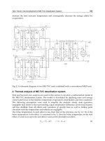
On the basis of the appearance of corrosion phenomena on the metal surface or in the
geometry of the equipment, corrosion is classified as uniform when the metal corrodes at
the same rate resulting in a uniform decrease of thickness or localized when corrosion
appears at a specific area in a part of the equipment. Corrosion results from differences in
aeration, concentration, pH, water velocity. Types of localized corrosion which are often
encountered in DPs, are illustrated in Figure 3.
Atmospheric corrosion in DPs installed in coastal zones is driven by the effect of marine
aerosols containing humid particles of NaCl. It is promoted by the formation of moisture
Corrosion Control in the Desalination Industry
81
Fig. 3. Types of corrosion in desalination plants.
Desalination, Trends and Technologies
82
layers on metal surfaces and by the chemistry of these layers .Climate change could
influence the macro- and micro-surface effects controlling either the chemistry or the
duration of these wet surfaces (Cole, 2010). Furthermore, hygroscopic salts absorb moisture
and form deliquescent salt particles which can greatly accelerate the corrosion of metals (Li,
2010). Corrosion damage increases maintenance expenses and generate problems in DP
operation. In a recent report, (Koch, 2002) it was estimated that cost of corrosion in the
USA is 276 billion USD on an annual basis, which represents 3.1% of the USA Gross
Domestic Product (GDP), including 36 billion USD corrosion in drinking water and sewage
systems.
6.2 Scaling
Highly concentrated SW tends to form thick scales by deposition of dissolved and
suspended solid such as carbonates, silicates and hydroxides. As SW is circulated the last
compound that tends to come out of the water is calcium carbonate. To prevent CaCO
3
scaling the feed water is treated with sulfuric acid converting the carbonate to carbon
dioxide CO
2
that escapes from the water. When phosphates and phosphonates are applied
to provide corrosion protection, careful control is implemented to avoid scaling by calcium
phosphate [Ca
3
(PO4)
2
] adding organic polymers containing carboxilic acids for control of
calcium phosphate deposition.
Chemical and physical pre-treatment of feed water is required to remove substances that
would interfere with the desalting operation and will damage the equipment, in particular,
the plastic membranes of the RO process. Pretreatment with ozone, a powerful oxidant and
biocide will remove sulphur, iron, manganese and other water-soluble heavy metals
compounds, bacteria, odor and color.
Some alkaline chemicals e.g. soda ash neutralize the acidity found in some brackish waters,
helps reduce corrosion and extends the life of equipment. Citric acid removes iron and
polyphosphates reduce iron staining but these pretreatments are rather expensive.
Scaling is controlled by introducing additives to inhibit crystal growth, reducing
temperatures and salt concentration. Inorganic, colloidal particles, e.g. silica or silicic acid,
hydrous iron oxide, aluminum oxide and organic substances in the feed water by special
pretreatments. Furthermore, a particular type of corrosion, known as microbiologically
influenced corrosion (MIC) develops under these complex organic and inorganic deposits.
Chelating agents and acid are injected into the feed water to prevent precipitation and
scaling on the RO membrane surface. Some DPs combine distillation with RO to produce
both power and water.
6.3 Fouling
By their very nature SWs provide and ideal environment for macro- and micro- organisms
to thrive. Unless properly controlled through the use of biocides; bacteria, algae, fungi,
mollusk will grow on metallic surfaces. These organisms secrete polymeric substances,
forming a film that generates acids and other harmful compounds that induce corrosion.
Furthermore, they deplete and establish oxygen concentration cells causing localized and
pitting corrosion. Many biocides are applied to prevent the formation of biological fouling;
such as gaseous chlorine (Cl
2
) sodium hypochlorite (NaOCl), chlorine dioxide (ClO
2
) and
Corrosion Control in the Desalination Industry
83
bromide salt (NaBr). These chemicals should be used with appropriate regulations approval
to avoid the proliferation of toxic agents.
The CRAs desalination equipment should be maintained clean and smooth to avoid
calcareous scaling on heat transfer surfaces and to diminish the propensity to biological
fouling on rough or polished surfaces. Acidic and alkaline cleaning is a mechano-chemical
operation easily implemented in CRA equipment, to remove biological fouling and mineral
scale since they alter the equipment surface performance and induce corrosion.
7. Corrosion protection, monitoring and control
Corrosion engineering and technology develop and apply methods and techniques of
prevention and protection to avoid the interaction of the equipment and its construction
materials with the corrosive factors of the DPs environment. Practical methods that
minimize or eliminate corrosion include selection of suitable CRAs (Encyclopedia of
Desalination, 2010; Habib, 2004; Malik, 2004) application of coatings, paints and linings to
carbon steel and galvanized steel equipment and cathodic protection.
The technical process of selection is usually divided in to three main stages:
• Analysis of the requirements and collection of the relevant information about the
conditions imposed by the desalination process and the corrosion resistance required
by the equipment.
• Selection and evaluation of candidate materials by screening of the information
collected in the first stage. Laboratory and pilot plant corrosion tests are performed by
exposing suitable materials in the desalination process fluids and environments (ISO
845 and ASTM G4, G31).
• Selection of the most appropriate material based on its costs, availability, easy
fabrication and repair, maintenance and safety.
Corrosion resistance is the main property to be considered in the choice of materials for DPs
equipment but the final selection must be a compromise between technological and
economic factors. It is sometimes more economical to use a high-priced CRA that will
provide long and trouble-free service than to use a lower priced material that may require
frequent maintenance or replacement. The selected CRA should be able to perform its
function safely for a reasonable period of time and at a reasonable cost.
Corrosion monitoring (CM) is the practice of measuring the corrosion events and rate by
continuously exposing materials probes in a body of water or a operating DP. Modern
electrochemical, electronic, mechanical, non-destructive and computational devices are
applied in the field of CM such as potenciometry, multielectrode probes, electrical
resistance, communication networks, remote CM, expert programs and artificial neural
networks. CM techniques provide daily warning of costly corrosion damage and critical
information, where the damaging event is occurring and about the rate of deterioration. This
information is essential to take decisions about the type, urgency and cost of preventive and
curative measures to be applied on site without delay. (Robenge, 2000).
Chloride ion (Cl¯), a main component of SW, can breakdown the passive film of CRAs.
Table 6 shows the upper limit of Cl¯ to assure corrosion resistant performance and how
their increment in Cr, Ni and Mo content enhances resistance to pitting and crevice
corrosion. This graphic display might serve as a guideline for selection of SS and Ni-base