flame safeguard control phần 6 ppsx
Bạn đang xem bản rút gọn của tài liệu. Xem và tải ngay bản đầy đủ của tài liệu tại đây (1.19 MB, 37 trang )
R4075E DUAL INDUSTRIAL
FLAME
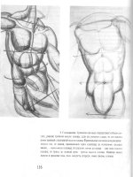
SAFEGUARD CONTROL (FIG. 63)
The
R4075E
consIsts
01
2 controls on 1
chassis
10
pro-
vide
Independer1t
~rvislon
of
2 indusUial burners.
11
can
al$O
be
used
for
redundanl
safely conlrol systems
or
for
l1JaI·fuel applications. With 2 controls
on'
chassis, the
mOUFllinQ
space r9QJlred Is
only
hatf (hal previously
Each control is similar to
the
R4075C, and thus is
ac:lapled
for
the 'Same
family
of
plug-in
name
sIgnal amplifi·
ers developed
for
the R4140. Any ccrrt>inalion
01
standard
and/or sal1·checking
flame
detection system can
be
used
by
mi;ling or
matching
the amplifiers.
For
BKample, a flame
red can
be
used
10
delecl
Ihe
pilot,
and
a self-checking
C7012E
or
F Ultraviolet Flame
Deleclor
can
be
used
for
the main burner flame. Since all amplifiers are plug-in,
Ihe
detection
rJ'\C:lClI3'can
be
changed anytime after Jnstallation.
Because terminal designations
for
lhe R4075E are
unlQJ9, II requires a special Q295A1054 Wiring Subbase.
The
R4075E is available
in
120 and 220 voll models.
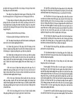
SEQUENCE OF
OPERATION
FOR
THE
R4075E
(FIG. 64)
The
q:>eration of the 120 volt model o1lhe R4075E will
be
described. The sequence
01
operalion
for
the 220 voll
model
is
the same; it just
has
2 addilionallransforrners to
provide 120 volts
for
the
shullers
on
C7012E
or
F Purple
Peeper Ullraviolet Flame Detectors. The schematic ill
Fig. 64
shows all relay
conlacls
in
the de-enerQized posl-
lion. Refer
10
file 8eq.Jence
01
{)peralion
on
the following
2 pages.
TIlANSo
50ECTIDN
A FORMER
T[R"INA~
STII.IP
ON;_-:-
~
SUIBASE-
P~UG·IN
~~~~IEF~~~:"'~'' '''''~
CHASSIS
II.ETAINING
SCREW
FIG.
63-
R4075E
INSTALLEO
ON A
Q295A1054
SUBBASE.
182
-
111.1
ffi
i
~~
~
~~
,.
.,
9~
,-
!)
,.
,
:Ii
;'
-j
~,
0'
'.
!<
"
"
~.
.
.
,.
-"'<:3
,
,
•
~
'
.
e
~ ~
. I
"'i
L
,
,
<A
,
,
,
,
l.loo_
~
~
,
,
,
,
I I
,
,,
I
!I
' ,
' ,
~"l
' ,
"I,,'
~
~:~
1]. 1].
,
"
l'!
,
ll'~
t; "'lou
HI
_.:
~~~
'"2."'~""O :!'!!
~gt
_.,,~I
111'"''
oJ;;::;
1 r <i;o U''''",l
I
__
~i:!"l
I I
~:a:
_
I'
I ,
.,.
~~
I I
i~"\
0";11
II
I'
u=>"
1 I
<>=>O:
I,
I
II
~
I I I
I'
I 1 I " 1 I
" • , 1
1 I
I I 1
II
"'50:
,
"'e:
1
II
~;;e
I I
~;;e
I
II
:;=::
I I :;:::;: I
•
+in;.
~~!
il.oW:!
"~1""
5~~
JR\';+
,'
I
""'"
I
II
':;1:1
I I
:::1'
,
I
~
"\
I I
;;::
~
I
I
uu~
I I
uuo.
I
I
l'i
'I
l'l
I
I
II
I
I
~
I I
",",'
,
I
O:li
I I
."
5 I
I
z~do
II
r~HD"-"
I
to.
~
~~:g~
-t
to
~
~~:!gt-i
'"
:I
i:!J,:
"
.1
;:iiiL
~i
-,""
>-
U
"I'.'
I
'"lIE""
I 1 r
-"~i5
I
I
"'
-nO
• I
- I
I.~:.:
I I r ,:-:.:
__
I I
.~
l , I
r-
® ®
C'J
(0)
(0) "
.
,
,
•
,
''''i
r
,
,
,
1:
,
:llffF11Ir~
'",'
-
~
.
<0
n n
-"
~
-
IE;;:
~
"""~
0
~_
~A-
_
.,
.,.
J
~
0"
e!::'
_
~
3~
OJ
~::!
_ _ y It
.
U···W·
.
UJ
~~~"
j"
- - - -
~:!:
.
,
,
",'I5I'
~
,.J:
'.
'.
"
»
!
I
,
,
11
-;r
I
,
.
~
,
:J
•
o
o
•
>
•
~
•
~
~
•
:bJbp
:It
Ii;
.~
5 i
~i
0
;:
l!
~u
!
6:;=~
'I'
~;
;o!
:i
l"l!"
o;;l"
0"
1~
""
~
,>~::~
~
i
ilid,~;:
II li
I!'~"
::'"
III
~
!:-:no
B~
'\~
~
!~ ;;;
"z
" ii
"",,,;:j,,
:;I
""
0:2
51
!tii;:i
2
"
0:
t
"
~~
~
~",~i:
~'t.
0::1
_
0:
~.:li
;!:
~U,~:::':
,
u
I<
L
j"-_,,
~
"
i1,
g:l
~I
:{',,:ol
oil:
~~
~
-g":I;~:
.
'.j"
~~~"
:!:II>
I,'"
:;;
:::~;:~
"!l~
i'
,.
",0:,,0
'"
il
~:~
i~
Ij:~
~;~
e!"
'"
~
o~
:l:!;'!
uS:
~;i!
;t;;;;
~~3
~ii
~~
~rl:;
~g!
,
•
"'i "'i
'"
"'i
o.'i:
:i
z -
Il:g;tl<!
~io:
~:
i!l"'!::: '".,,0_
t~
i~:"
l'l'l!t;i
z"'
u~~
!
II
'~O
It
,
iit
:c",~
~~:!::!l
=~
~~~i !~~~
~
,
i
:Ii!!
I"
:::
•
,0:
zo"
u
-,
.,lI:i
="
i
•
0-
"
:~
:;:~=
~:'l!"
',-'
'l!!::;~
2
::
~
~-
: 1:"
5'1'~:
~
'
-
.:
~'"iJ "~::3
li
lj
!l::l"S/o:
~
"o
"-~
g"!,,~
~a!:li
:::
-,~
>5:"~
D::;8:;:
:l
_OM
j!!i!i'"
U§i!: !
ii
~~~i!:~
~§~~
~
!il
!i::~::~
;:;l~li!
~
jo:
,.,,,
> "
0
~rl"
- "
z"-
-w
1-"
f'"
z
i:
~:oi
:::
~~:-::
~
=g
i~~~!
~~~3
~
~~
~lH~
B~a
i
'" '" '"
"i
w
j!:
~
'"
~
~
Z
"
i
'"
o
~
ii:
w
o
2
"
'"
~
o
u
'"
o
~
w
~
2
~
l:l
~
Ul
o
z
"
2
,,::l
.
"'~
,,0
,,"
-'"
Ow
!'!j!:
!C
20
w~
xw
Uo
OlO
02
!!!1-
~
-0
~>
2o
_N
Ol_
,
W
ci
ii:
.'
SEQUENCE OF OPERATION FOR THE R4075E
lRe
R4075E consists
of
2 identical sections. A
and
B.
This sequence
of
operation is
tor
one
section. The operalion
01
the
olher
section is identical.
NOTE: Italics denote special applications.
NORMAL
OPERATION
OPERATOR
ACTION
R407SE OPERATION
SYSTEM OPERATION
TO
START;
1.
Reset
an
limits. O:ls:e the
master
_h
on'
the
.~
silencing
swilch
(If
used).
1TI0>t
Cb
ret
push in the
sr
ART
buttm'
_before
the
rna_
_ itch
18
COITIpletely
cbsed.
1. a.
b.
Poo¥9r
iI5
applied
to
terminalS
thrtJUgh
the Ifllits, alarm sll&ncing switch, and
STOP
station; the plug-in amplifier is
energized.
Power
Ie
applied
to
terminal 7 (through
the
alarm
silencing switCh}.
Ilnd
to
tar-
minal 8 ('through
11<2).
,.
11
b.
Standby
to
start.
The
alarm is energized.
2. Push in
1t'Ie
START button on
Itll~
S445A
and
I1:lld
it
in.
2.
a.
Power
is
appliell
Ie
the ignition trans-
former
and
to
termiN.I 3
through
thE!
limits,
alarm silenCing
~h.
STOP
6't!ltion, imernal
jlmper
in
trnI
S445,A,.,
and
START
S'tlltion.
2.
a.
Th.
ignition
transformer
on'
pibt
vaJve
(or 1st stage oil valYe) afe ener·
glzad.
The
pilot valve
opens
and
the
pi-
bt
is ignited.
The
flame detector de-
(ects
the pilot flame
b.
Relay 1K
pUll$
in lIlrough
2K2
(sale
6't!lrt contacl) Contact 1
Kl
eto$MI. by·
passing
2~:
1K2
opens
on'
'KJ
clo!l9S.
b
The
alarm
i$
dlHlnerglzed.
,.
If
M R7247C
Dynanjc
Sdf
Check
Am-
pMer
is
used,
power
is applied from ler-
c.
It
a
C70f2E
rx
F Purpfe Peeper Ultra·
viciel Flame Derectrx
('wI~h
se/f<;heck·
3. Release
1I1e
START
button.
4. ~.n manual
mol'
vaJve{s}
"'''
~
used}.
TO
STOP'
S.
Push in the
STOP
button
on
the
S4'SA
,,'
"'''
•
;,
until
the
.larm
is energized.
e.
~pen
the
alarm
silencing
_h
used).
7.
Open
the
master
switCh.
mihal3
through the sciid stare switch ih
I the amplifier (be/ween amplifier term!·
nals
16
Md
ll).
/0 terminal 12.
,.
When the
pibt
flarne is d6t9Ct8d, relay
2K
pulls in. Contact 2K1 closes, by-
pusing
lIlll
START station
fran
ter.
mil'\8.l 6,
lIlroullh
2Kl
and
110,
10
ter·
minal
3. Contset 2K2
opens
ContaCl
2K3
closes: power
is
applied Irem ter·
minal 3111rough 1
K1
anO
21<3
to
tsrm~
nal
S.
3.
Normal
operation.
including
setl-chec:k-
ing or the
flarntl detectioo sysiem
frf
a sell·
checking system is used)
•
Normal operation.
,~,
S.
a.
_.
-
I&rminal
o.
This removes
~
fran
terminals 3,
S.
and 12. The plug-in amplifier is de-
energized and relay
2K
drops out.
b. Relay
1K
drops out:
11<2
closes.
,.
All relay
ronlecle
are
rasat lor the
nelCl
startup.
o.
Power is removed
fran
lermjnals 7 end 8.
7.
None.
ing leattore)
i$
used,
the
shutter
is
el"lEW"-
gized.
,.
Tho
automatic
main
fuel vatve(s}
;,
energizeo.
The
valve(s) opens lind
lila
main
bumer;$
ignited.
Tha
system
i$
in
th,
,",
condition,
(If
•
mMLIally
opened valve
is
used,
the
maoil
burl"lEW"
will nol be
ignited
unlil step 4 is com-
pleled.)
3.
The
igntfun
1rlinstormer is de-energized.
•
The
main burner
is
ignited.
The
system
1$
in
the run concjtion.
S.
a.
The pilot valVe (or
1st
stage ell
valVe)
and
1t'Ie
main
fu&t
VIltve(S)
are de-ener·
giZed. The valves clo6e and the pilot
anI:!
main
burner
flames go
Out.
b.
The
alarm
is
energiz80
,.
N~.
0
The alarm is d&-energized.
7.
The SyStem is de-energizad.
18'
SEQUENCE OF OPERATION FOR THE R4075E (Continued)
SAFETY OPERATION
-
ABNORMAL. CONDITIONS
R4075E OPERATION
Relay
2K
pulls
in
when the name (or flame-
simutaTing
condiOOn)
is deteel&d.
Conlacl:
21<2
opens, preventing relay
1K
trom pulling
in when
the
START
button is
p~sed.
•
Contact
1
K3
stays open:
the
STAAT sta·
tial is no! bypassed. Power is removed
fn:n1lBrmil"lRl J whOl'\
the
START
bl./tt:ln
is
relaased.
•
Contact
11<2
remains c'oseO.
•
Conuel 1K1 flmains open.
Relay
2K
does
rot
pUll
in.
•
Contact
2Kl
slBys open:
ltle
Sf
AHT
s\a.
tbn
is not bypassed.
When
1M
srAAT
butIl:ln is released. power
~
retJ"lO';'ed
fTtm t9nTlinll\ 3
and
relay
1K
drops
out.
•
Ca1tact
.21<3
stays open; power canl'lOl
~
applied tJ terminel
5.
•
Contact
11<2
closes.
Relay
2K
drops out.
•
CorTtact
.2K1
opens: poweI" is rerroved
fftm
terminal 3 and ra!ay 1K drops out
•
Contact
21<3
opens;
power
is
I'8r'l'lOWd
fftm
terminal 5.
•
Contact
1K2
cbses.
All
felEVJ'8
drop
out
Relay
2K
cannot
pull
in
When
IN
syst1Irn Is
startBd-ume
operation as if N
pitrt
Is tI:lt
ignited.
Sale Start Check - A
"name,
or
a
oondi-
ticn simutanng.8 name.
is
present be-
101'9
"lt1e
START
button is pressed.
. -,-
./,
-
The pilot
/01"
lsi
stage
oil burner) is no!
ionited.
The
name goes
out
during
lh&
11.Jn
perod.
Manen\aIy
power
lil~lX'll.
If
USING
A SELF·CHECKING
FLAME
DETECTION
SysrEM'
The
name de18Ction system laila While
h
syvt8m
is IU.med of!,
The name det8Ctloll $Vslern tails dur·
ing
tl1e
run period Wllh !he
burner
~ng.
Relay
2K
dropa
out-same
operation
all
II'
the
1Ieme
gee!
0Ul
SYSTEM OPERATION
The
pilot
lor
1st stage oil burner)
Is
ignited
1'Ihen the
STAAT blJlton Is pressetl. 1M
IN
sy5tem
'oWl
shut
down
when the STAAT but·
bn
is
released.
•
When
tl1e
START
button
i,
relea5lid.
the
ignition transformer and the piot
alve
(or
lsi
:Mile
Oil
\/aue) are lle-enerllized.
The
vaNe
closes
and
!he
pi'ct
1\ame
goeo out
•
The
alarm remaine. energized.
•
The
8ubnatic
main fuel valve(sl canrot:
be
en6I'giZ8CI.
ststem
cannot
be
lllarted.
•
When
1M
srART
b~
is relessad.
tt1e
ignition lrans10rmer and
ltle
pilot valve
(or
1M
stage oil
Valve)
are
de-energized.
The
pilOt
vatve
cbsa$.
•
TIle
automatiC
main
fuel valve(s) cannot
be energized.
•
The
alarm is energized.
sa/Qty'
sh
tdown
OC:CUr3.
The
pilOt
valve (or
lsi
llIage oil valve) ill
•
de-energized and I!"e valve closes.
•
The main fuel valve(s)
ia
de-enMlJized
and
the varve(a) closes.
The alarm
Is energized.
•
safety
Elhutdovm oCCunl. but the alarm
is
not
lJIr18l'"giZed
umn
power
18
rastonld.
safety
ElhUldown
oCcurs.
safety
shutdown occurs.
185 11·97558-1
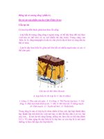
R4138C,D INDUSTRIAL FLAME SAFEGUARD
CONTROLS (FIG.
65)
These controls directly replece older R4138A
and
B
models to meet the lates! rElQJirements. They
are
espe-
cially Suitable where Icng petilXi3
01
burner operation with·
out s/'lulc:bwn are normal, such
as in heat-treating ovens
and kilns.
The R4138D is (he same as the R4138Cwl!hthe
adc:lilion
01
a
jXl'I'Ver
failure override circuit
10
prevent shut-
down
during very short;power outages
(,oower
line switch-
Ing
of.
1 Second or less). The A4138C
is
available in
120,
220,
and.24O
volt
rtlOdeIS;
the A4138D
Is
available only in a
120 vol'model.
SAFETY FEATURES
The A4138C and D provide a
Safe
Start
Check
for a
flame, or a condition simulating a flame,
at
startup. If the
flame"relay
2K
is pulled in before the STAAT button
is
pressed•
.2K.2
is open, preventing the load relay
1K
from
pulling in.
The system cannol
be
started until the condition
Is
corrected and 2K drops
PUt.
They also
prOVide
safety shutdown
on-
- failure to Ignite the pilor. (lockout will occur
t1the
START button is held in
IClIlg9f
than the
10ckPUt
switch liming.)
-loss
01
flame during the
rUl"l
period.
-failure
in the flame detectiCfl system, If e sell·
cheCking system
is'
used-see
Table
II.
(L.ockoul
will occur it lhe START
b rIlon
is
held in longer
than
the
lockout switch timinQ.)
On
safety shutdown. the pilot and main fuel
valve(s)
are
de-energized.
11
used, the exlernal alarm is energized. The
STAAT bulton must be
manu8JJy
pressed to restart
the
system.
"the
lockout switch
trips.
the load relay 1K
drq:>s
Oul
and the lockout switch must be manually reset
to
rEt-
start the system.
OTHER FEATURES
" A
plu~in
$4.27D
Purge Timer is available
as
an
ac·
cessory
(0
provide e timed purge period prior
to
the
manual startup.
"
An
optionei remole reset assembly allows resetting
the lockout switch from a remote location.
" Irlcandescent indicator lamps (FLAME OFF,
PURGE COMPLETE, FLAME
ON)
prOVide
a visual
check:
011he
system condl1ion.
• The R4138C or D plugs into a subbase or cabinet
ElQJiA?OO
with quick-connect
C'-ontacts.
• All field wirinQ (except for the optional remote reset
assembly) is connected to a terminal strip
on
the
subbase or In the cabinet. The R4138 can be
re-
moved easily withoul disconnecting any w·lring.
" Clear plastic relay covers help prevent conlamina-
tion, damage, end lamperinQ.
"
An
ALARM terminal
Is
available to operate
an
exler-
nalline
voltage alarm on salety shutdown.
" A zinc-dichromate finish resists the corrosive
ef-
fects
01
most induslrial atmospheres.
KEYED
IIECEPTA(L[
FOR
PlUG·IN
AMPliFIER
SPRI",!>
CL'P
01'1
CHASSI~
PlUG·I",
INCANDESCENT
FlAME
SIGNAl
INDICATOR
~,,"PlIFIEpR
lAMPS(J)I\
•••
_~ \
,_
'\C<'"
~
s'!
FLAME
5IGI\IAL
\
METER
JACK
RELAY
ZK
THREADED
fl.ELAY11(
""OU",TI,,,G
STUD
RELAY
JI(
RECEP'TACLE:
FOR
PVRGE
TIMER
FIG.
55-COMPONENTS
OF THE R4138C
OR
O.
186
-
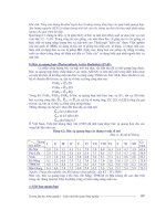
SEOUENCE
OF
OPERATION FOR THE R4138C
OR
D (FIG. 66)
The cperalion
orlhe
120voll models
oflhe
R4138Cand
D
win
be
described. Theseq.Jel1ceofoperalion for a 220 or
240
volt model
ot
the R4138C is the same; it just
has
an
aci:jitionaltransformer
10
provide
120
volts tor
the
sMutler
:
If·~
,~
,o~
"I
.""n.
1 .MO
~'SC€L""M€OUS
1
IM'U.OC'"
,
'u
2
;
~
r &
,~,
,
.l
I,
T
5
,
,
- -
,
I
&
"f
~'''N.e
"'".'N
'~'u
0
"H'.
,.CO
,
I
D€1r(ftI.
I
__
'-;'c "
,
•
l~
1
If€
'n
,
"'.>t.t?
"
._ _.
•
"'\IT1"'
•
•
(£,
00
,
/:::~~
~~.&
,
€ D"
1.'Ol
, ".
'"
"
,
,
,
"
,
II
~TO.
or"II:
,
••
u,
R-
10"f€1'I)
fn'l
,",
I
,
r •
I
I,U
&
,
,-
,
\r,
y
co
~,.,
.u.,
10\
I
,
~
T
I
_'
e
llI"Sl
I
,.,
I
I'
' "'
T
ITO,
."
l
,
••
, I ,
,.,
I
'"'
".
,.
,
,
,
,
,
,
,
,
,
,
,
,
,.,
,
,
,
,
I
,
,
,
,
,.
,
,
,
,
, ~
'""(')
~ ;
I _
••
AI
o
••••
'O€
"
,otU
CU1.
I
I
I
,
"
'"
•
",
00
I
"
"
"
-
&
"'''.'01
O'sc_.C"I.l.O
; ,
L.CI.O~.O
CT'O
.'QU'.'C1.
&
"'L.CIT
UN.
Ju
M;
,
II:(U_O
'0"'"
ce
OO
I"
'IOCIl
"""T
eAT><I
LIN.
IT
I.SO
~U-"'" ".eu
o
"ou UV1n:
& '
n
o'
,"".
c""11
D.'
""
I"II:UO:.
ULT
IOUT
o.n~TO".
LlJ.
"H'"
uTTl"
,.1::1
1
""LV",
C"',,,
D
••
"'''
1"11:
U.
, v,
<:Ct'ltTO"
"IT~
,(~.C.,
'u"'-
""'
••
TO
0"'.'
"'I
' n
"
~""LJ.O
TO
,
""
.
.,~
a
,,,,",,UGH.
SOUOI1U'
'''TC~
t~T~'
.>,.>c
Ov
'C
"LF
c
Cl<_
IFI.",
~
u.o""".U'"
"'.c"' .
CO
OT.O
TO
.'
"""
R
TO
"'''0
,""
OI
OOS'
& tF
"'OH
.'''.'", IlLOC
UUCl.
v
,.
"""c()HT.~T
,.,
.'"
TTl",
"'ND
_R
,
u.lO
.~.N
,
'N
11
•
"0
.
on
a
C7012E
or F Purple
Peeper Ultraviolel Flame
Deteclor.
The lad:ler diagram (Fig.
66)
shows all relay contaclf;
In
the d&energized position. Refer to the
S8QJence
of
0p-
eration on the following 4 pages.
,
,
,
,
,
."
0'.""
O'''
T.
e'
••
0<"'''0''10'
v
CO"T
.cn,
(
00.
••
,
,
,
"'O'OTO.
"'"
VOL.CI
D
CO."(T.)
"L.CI'U.Y€
0.
~
Gil
~
~
_'TIl
~
=,:.~~,':;'~':
':':'~~~'~;;~Uc'=:"~;;.'Jo~~J
~"u."'''-
u
f.
l'H€
,
Tell
,.
cL.Dloll.o.
&.
IF •
,
".
ST
••
'
'."
••
"""
,.
roar
0.
TH,
IT"""
""'TC"
,.
ca.H'C'l"'D
OI
••
CTL
v
TO
"
& _
,.
·."'.51.T"",
TII '
"N
'U
OR
••
u,v
_0
"""
"lMOn:
0l"l
T1001.
& , '
,Te"
It
100.
U"O,
,~
••
,""
ST"
nOOl
"'u.
O
CUD
D''''CT.V
"'
".,
"""
nR
'~
L .
CO
KTtO
TO
e,
~
'H'.OS"
•
fC~
O
.~.
C''''''"''O
UX><5-
A
""n"",
•
.".
F~
",,"o., v.
" u ""'0 0
v
'1<
TOIUU,
,,,
,.
,
T V
~u
_R
,A
"TN
'
v
•••
' C,otUIT _
'"~
TN'
,U.'
v
FIG.
66-
SIMPLIFIED
SCHEMATIC
DIAGRAM OF TME
120
VOLT
MODELS
OF
THE R4138C
AND
D
SHOWING
TYPICAL
FIELD
WIRING FOR A GAS
OR
OIL CUTOFF
SYSTEM.
'87
71-97sss 1
SEQUENCE OF OPERATION
FOR
THE R4138C, D
NOTE: Italics denote special 8HJlications.
NORMAL OPERATION
OPERATOR
ACTION
R41J8 OPERATION SYSTEM OPERATION
TO START-
1.
RElsel
tI111
Ioc~ut
switch
on
tile
1, a.
ap~lied
"
terminal
,.
a.
The
lan(5) s\lIrts
R4138. Reset all limrts.
and
inter-
"
"
•
"
Ihrough
thE!
il1lerlocks
and
limits, and
'bcks.
Close
the maste!" SWitch.
to
terminal 3 Ihrough the
jumper
Irom
larminal L
1:
the
plug-in amplifier is 8f\o
ergized.
b.
Po-
i'
applied
"
terminal b.
The
alarm
115
energized,
bU1
may
be
('tHough the alarm silaneing switl:hl,
"
-
turned
off
by
opening
the
alarm
si!enc-
and
ID
I8rmineJ 16 ('through 3K1). ing
switch
(If
u~d)
,
"'""'
•
app"ed
"
terminal 18
,
None.
(through 3K3):
ltle
FlAME
OFF
(RED)
lamp fights.
2.
Open the
damper
D
high
fire posi- 2. a.
None.
2. a.
The
high
fil"ll
interlock
closes
Whe!1
the
lion
(rt
mahually
operated).
damper
Is
open.
(The
damper may
open
eu1on'lalicalty.)
b.
•
appfled
"
terminal
17
tI. The purge
perod
belilins: the lan(s)
~gh
the high fire irrtBr1ock)
and
to
Pow"
clean
the
combustion
chamber
of
un-
lhe
mobr
ofltle
pur~e
timer
(through bU!l19d fuel
and
fuel vapor.
PT1):
1he
purge
timer
starts.
c.
At
the
end
01
lhe
preset
time. PT1
,.
Relay 1R pulls In: 1R1 closes
to
bypass
opens
and
ll1e
purga
timer
stops. PT2 the
nigh
fira jnter10ck
end
keep power
ctJses, IlPPtyinll
power
Ie terminal 6 applied Ie the
purlle
timer. (If power
is
(Trom terminal L
1);
the
PURGE
COM-
removed
In:m
the pur'ile timer, it will
PLETE
(GREEN)
lamp
li'ilhts. reset, PT2 will
open.
anll
tile
system
cannot
be
started.)
3. When the
PURGE
COMPLETE
3.
Nono. 3.
The
hl'ilh fire inter10ck
opens.
and
the
'uw
,,, ,
(GREEN) I8mp II'ilhts. close
tile
inler10ck
"co
"'"
damper
t:J
low
fire
posi1ion
damper
Is
Closed. (The
damper
may
cbse
manualo/ operated).
('
""""
"'"
automatically.)
4.
Close the
alarm
silencing
switch
(II"
,
None.
,.
The
alarm is ener'ilized.
it
WIlS
opened
in
step 1).
5.
Push
In
the
START
button
and
5.
e.
~er
is
applied Ie the
i'ilniOOn
trans·
5.
a.
Tha
i~nrtion
transformer
Is
9n9r~lZall
t1:Ild
it In.
former
and
to
terminal 6 tthrou'ilh the
NOTE:
To
avoid
nuisance
low
lire start lnlertock
and
the
sr
ART
statkJn).
shutcbwns
when
not
using
b.
~er
Is
applied
to
tarmir.al
7ln:m
te!'-
b.
None.
a
purge
liry'let,
wait
at
lea$!'
minal 6
(II1rou~h
the
low
lire start InlBr-
10
seconds
after
the
tan
in-
lock, START statkJn,
intemal
jl.M"lper,
terlock
closes
before
push-
STOP
staOOn,
,"d
alarm
silencil\l;l
ing
in
the
START
bullon.
,
switch).
RBlIlY 1K pulls
In
throu'ilh LS1, 2K2,
aNl
HTR
,h
LS (\oCkout
1'I9lIter1.
thus provin'il lhlt continuity
of
lhlt heater.
(1l 1K1 ebses. applyin'il
power
to
tur·
,.
(1)
TI"MI
pilot
vllive
(or 1st
sta~e
oil
minai'S
tro-n
terminal 3.
valve)
•
ener~lled.
The
valve
opens
and
the pilol: (or
191
sta'ila
Oil
burner) Is
I~n~ed.
(2)
Jt
the pilfJl/lnlc
lumper
wi/1l
I'!~s
been
clipped
fr:T
8 continurxJs
(sr~ng)
piJfJl
app/iC81ion, the tfame derec-
rion circUit
fO
the amp/if/Sf is
com
pleted.
(2l
1K2 closes.
(3)
lK3
cbses;
the
LS
HTR (lockoul (3)
None
.
be'ilins
heatin'il
(tty
autJtransfonner
action
of
1K
thf'OU'ilh
1K3 and
21<2).
,h
hea""
d.
If
8 C7012E
cr
F PurpJe Peeper U/tfit
pJiffet"Js
used,
power
is
applied
from ter-
d.
If
an
Rrn7C
DpIarric
Self
ChecJc
Am-
vir:itJt
FlsmtJ
DBtacta
(NitI'! seIf-eheck·
rrifllll 7 t!roUgl'! Itle Jumper to
trJm"inaJ
Ing
feature)
is
used, the
shtmer
is ener·
13,
t!roU¢
the sr:iid "'are swircfl
in
the gized.
81tfJIiffet"
(between
ampli~B>'
tfJi"trlnaJs
16
fIftd 17),
10
ttrrTinaJ 12.
'"
••
SEQUENCE OF OPERATION FOR THE R4138C. 0 (Continued)
NORMAL.
OPERATION
(cOflrinued)
OPERATOR
ACTION
R4138
OPERATION
SYSTEM OPERATION
None.
•
The "arne detector detects the
.""
nlllT!8
lor
llrt
stage oiIl1ame).
r.
When the llama
is
detected. relay
2K
pull,
in.
(1)
2K1 closes, bypassing
the
purtle l. (1) None.
~m8f
contact PT2,
low
nre
stan
interbck.
START
slam,
and inter-
nal jumpel".
Power
will
be
applied t:I
terminal 7
{tmm
terminal 3. tt1rcugh
2Kl
ID
tenninal
e,
and
tI1rough
tI1e
STOP
stillion
and
alarm sileJ'ICing
!Witchl tJ
tvJld
in relay
1K
(unl",
Ih8
limb
open.
the
STOP button
il
pressed.
oc
safetj
shulQaoNn
occurs.
.
(2)
2K2 opens; the
LS
HTR stJps heat·
(2)
None.
Ing.
(3)
210
cloS85,
applying power
lD
tar·
(3)
The
aubnatic
main fuel vaMl(a)
jljI
minal 20 (frt:rn terminal 3 throUgh
energized.
The valwl(s) Optms and
1
Kl).
Relay
3K pulls
in
and
the
the
main
burner
is
ignited. The sys-
FLAME
ON
(WHITE) IlImp
Wghts.
lern
is
in the run conditbn. (If
II
mat1lJ8Ify
opened
vahe
i,
usBa',
fhe
main
l:IUmet
will
not
be
igrittKi
unrif
step 7
is
compleuKf.'
,
When
relay
3K
pulls
in-
(1)
3K1
opens.
rel'TlOVing
power fn:m
,.
(1)
The
alarm
is de-energized.
terminal 15.
(2)
R4138D only:
3K2
closes, bypass-
(2) None.
ing
110.
Relay
11<
can pull back
in
after e fT'OTIenlary power failure if
31<
is
still pulled in.
PI
310
opens,
rel'TlOVing
power
fn:m
P}
Retay 1R drops out and 181 opens.
_,
18. Th. FLAME OFF
{REO)
lamp
goes
out
The
purge
resets
F'T2
~,
'n"
'''"'''.
rerroving
power fn:m terminal
5.
The
PUAGE
COMPLETE
(GREEN)
lamp
goes
out
5.
When
the
FLAME
ON (WHITE) 5. Normal operation, including
self~l1eck-
5,
The
ignib't
ltanmlTl'lel" is de-energIUld,
lamp
lights. relaase ltle
START
ing
of
the
name
deteeiion system (rl a self-
checking
system is used).
bullon.
7. Normal operetion.
7.
Open
manual main
Iw/
valve(s) 7. The main burlJ8f
is
igrrlfKi.
Too
system is
(it used).
in
100
fUn condition.
TO
SIOP'
a.
Push
in
the
STOP
button ;tnd 8. a.
Power
Is
rer'l'W:'Ved
lmm
terminal
7.
8. a.
C7012E, F
shtJrtBt'
is
~D1d,
hold it in until the FLAME OFF
b. Relay
11<
drops
out
lKl
operul. re-
b.
The
pilol valve (or
lsi
stage
oil
valve)
(REO)
1=.
IiQhls
or
U!TtII
all
moving power
lmm
terminal$ 19
and and
the
main
fuel valwlfsJ
ere
de-ener-
relays
drop
out
20. Relay
31<
drops
out
and the FLAME
gized.
The
valves Close
end
a11l1ames
ON (WHITE) lamp g.oes
oul.
go
out.
c.
When
relay
31<
drops
oul-
(1)
31<1
close:9.
c.
(11
The
alarTn
is
en8l:gizlld.
(2)
310
ck:ls&6:
ltle
FlAME
OFF
(REO)
(2)
None.
,
IlIrnp lightll.
Vv'tlen the lIames
go oul. reilly
2K
,
None.
drops
out.
e. All relay contacts
are
resellor
the
next
None,
startup.
9.
Power
~
retro'tIed from tel'min4l:9 1S
end
9.
The
alarm
is 4e-e08f"9iZIJd
(ll used).
9.
Open
the
alarm
silern:ing
svwiIch
15.
10.
Power
is rllr1'DWd from tel'miMIs L1
and
'0
The lan(9)
stipe
end the
systIlm
is de-
10.
Open
Ihe
masler
swilr::h
3.
The
plug n amplifier is de-energized. 808I'"glzed.
and
the FLAME
OFF
(RED) lamp goes
,,"
189
71·97558·1
SEQUENCE OF OPERATION FOR THE R4138C, D
(Continued)
SAFETY OPERATION
ABNORMAL
CONDITION
R4138 OPERATION
SYSTEM
OPERATION
Safe
Stan
Dleck-A
flame,
or
a condi· Raley
2K
puns In when
the
name (or flame- The system cannot
be
started unm the con·
tion simulating a name,
is
present be- simulating condition) is detected.
Contact
ditiol'l is corrected and
2K
drops out.
lore !he STAAT button Is pressed.
2K2
opens, prewnlirlg relay 1K
fran
pul~ng
NOTE:
r,.s
c.heck does
not
apply
if
us·
in
when
the
START button. is pressed.
inrJ
a.cootinuous (st8flding) pilat.
,
K1
stays open; no
IlOM'I'
can
be
ap-
•
The
pilot
valw
(or
1st
stage
oil valve) and
•
plied D tlIrminals 19 and
20.
the
automatic
main
fuel vatve(s) cannot
-
be energized.
•
Relay
3K
cannot pull in; 3K1 and
310
re-
•
The
alarm remains energized.
main closed.
The
FLAME OFF (RED)
lamp remains on. The
PURGE
COM·
PLETE
(GREEN)
lamp
may
also
cane
,
DO.
No
name
is
detected.
so
relay
2K
does
not
The system
c~
be
started. The ignrtion
The
pilot
(or 1st
stage
oil
buma"
is
not
ignitBd. pull in. transtormer is de-enerllized
wheo
th.
START bbltlDn is released.
,.
Contact 2K2 stays Cbsed;
the
LS
HTR
"
Salety shutdown with lockout occurs.
(lockout
II'I'o'itc:h
heater) heats until !he
The
lockout switch
must
be manually re-
lockout
switch
1I1ps
(If
the
START
button set to
try
to
restart !he syslem.
is held in longer !han
the
'Ockout switch
timing).
a.
lS1
opens and relay 1K drops out. a. The pilot valve (or 1st stalle oil valve)
1
K1
opens, removinll
power
from Ier-
is
de-energized,
eo'
th.
valve
minaJ 19.
,""""
b.
210
stays open;
power
cannot be
b.
The automa1ic
main
fuel vslve(s) can-
applied to
18nTIinaJ
20.
,.
not be energized,
Relay
3K
cannot pull in; 3K1 and
310
,.
The slerm remains enerllized
remain closed.
Tho
FLAME
OFF
(RED} lamp remains on.
2. If
the
START button
is
released before
2.
Safely
shutdown occurs.
The
START
the Iockolll swill:h
trips-
button
must
be manually pressed
to
try
to
restart
the
system,
a.
When
the
START
button is released,
not bypassed.
When
the
START
but-
2K1
stays open: the START station is
the ignition transtormer is de-ener·
ton
is released,
power
is
removed
gized.
fn:m terminal
T.
b.
Relay 1K drops
out
end 1
K1
opens,
b.
The
pilot valve (or 1st stage oil valve)
removing
IlOM'I'
fn:m terminal 19.
•
de-enerllized,
,,'
th.
,,"'"
,
closed,
210
stays open;
IlOM'I'
cannot
be
,.
The
eutomatic
mein
fuel valve(s) can-
epplied to terminel 20.
not be
__
glzed.
,.
Relay
3K
cannot
puK
in; 3K1 and
310
,.
The
elarm remains energized.
remain closed.
Th,
FLAME
OFF
(RED) lamp remains
011,
System shutdown occurs
period.
NOTE: Safely operation is
the
same
if
The flame
\lOBS
out
during
the
run
Relay 2K drops out.
•
The
pilot vlllve (or 1st
stall~
oii valve) and
the
mllin burner is
rxrt
ig nired
in
a
•
2K1
opens, removinll power fn:m termi-
the
automlltic
mllin
luel
vsive(s) are
de-
system w;th an
interrupted
pilot
nsls 8 and
7.
Relay 1K drops
out
and
1K1
energized, and the valves close.
(obtained
only
by
the
addition
01
opens, removing JXlwer
from
terminals
19 and 20.
The
FLAME ON ('NHITE)
eJdemal circuitry). lamp goes out.
•
Thll
alarm is energized.
The FLAME OFF (RED) lamp lights.
•
Relay
3K
drops out;
3K1
and
310
close.
The
system shuts down. All valves
lire
de-
A limit
or
interlock opens. Power is
fllITW:M'Id
fn:m all terminliis except
15. All indicator lemps go
out
and all relays energized, and
the
valves c!osB. The IIlarm
drop out. 3K1 closes, applying
power
10
ler- is energized.
minal16.
190
~.~
SEQUENCE OF OPERATION
FOR
THE R4138C, D (Continued)
SAFETY
OPERATION
(continued)
ABNORMAL CONDITION
R4138 OPERATION
SYSTEM
OPERATION
Momentaty
power
"fsHure.
.
.
B4138C;
Power
~
r9IT'QYed
from
all
tanninals.
aN
lndl-
calor lamps go out. and
all
r8l6y, drop out.
llill&
Power
is
rerooved Irem all terminals. all indio
calor
lamps
go
out,
and
aU
relays except
3K
drop
out
The
charge on capacitor
Cl
will
hold in
3K
tJr
about 1 second.
•
It
poWllf'
is
restored before 3K drops
out
end before
lila
plot flame (or 1st
stage
oil
!IamEI)
~
out-
-3K2
will stay
cbsed.
bypassing
lK3;
3Kl
and
3K3
Will
stay open.
- rllfey 2K will
pUll
bacl( in:
2Kl
and
2K3 will cbse. and 2K2 will open.
-the
STAAT
staliol1
will be bypassed
through
2Kl,
the
STOP
statkm, anl:l
the
alarm silencing switch.
- po
er
ill be reappliel:l
to
lerrninal
7.
- relay 1K
111
pull back in thrtluOh
LS1 ani:! 3K2.
- operation
Will
re!lJm
to
normal.
•
If
3K
l:lrops
OU1
before power
is
r&-
stored-
-
3K2
will
open,
so
110
will
nat
be by-
passed;
3K1
ani:!
310
will
cbse.
- relay 1K
cannot
puU
back
In
since
both
110
8Il1:l
3K2 are
open.
~
1
K1
stays open. so
3K
cannal
puJf
beck In.
-!he
FLAME
OFF
(RED) lamp
win
liOh1
when
poWllf' is
rr.mred.
•
II the pilot
flame
(or 1
st
staOe
oU
name)
ooes CM before power
Is
reslDred-
- relay
2K
C8Il1WJ1
pu~
back in. 80
2Kl
stays open.
- the START sta1bn
cannot
be by-
passel:l.
- paMll'" will not be respplied b terml-
r.a17.
- relay 1K cannot pull
be,ck
In.
- relay
3K
willl:lrop out; 3K1
anl:l
JIC
will close.
-lhe
FLAME
OFF
(RED) IM'lp will
light
when
paMll'" is restJrel:l.
The system shut:l down.
The
alarm is aner-
llized wherI power
Is
restored.
•
If
pc:JYIIer
is
re:Jlored
within 1 second
llnd the pilot llama (or 1st stage cil
name) is still
burning
(1l1e
\/lWe
must
be
sbw
cbsino), rormal
OPer4OOr1
will
be resumed.
The
aJarm
'l¥ill
not be en-
ergi2ed.
lIthe
main burner
name
hal
gone
out, it will
be
reionifed
by
the
pi-
lot
nama. (Power failure override eir·
cuits
may
ha~e
b be
al:ll:lel:l
b the pilot
valve
and
me,in vaNe(s) b enS\J{e lt1al
they
1:10
not
close
on
a mctr\EIntary
power
interruption)
•
The
systBrn
~huts
llown. All valVes are
I:IlHIn«gizel:l, anl:l
the
~a'-
cbse.
The
alarm
is
8I18rO~ed
lIltlen
PQ't¥er
is
_.
•
The system
~huts
llown.
Ad
valves
are
l:Ie-energizeG,
8111:1
the
valves
clow.
The
alann
Ie
8l'18fO~ed
when
poWllf'ilI
_.
IF
USING
A
SELF-CHECKING
FLAME
DETECTION
SYSTEM'
The
naome
l:Ietec:tion system falle
\fIthi1e
Relay
2K
canrot
pull in
when
the
9)'SI&'n
is Safety
sl'w.1l'lSoWn
occurs.
LJx:kout'l¥ill
occur
the system is turnel:l
all
or
l:Iuri~
the
startel:l-sarne
OperllOOt'l
as
it
lhe
pibt
(or
it
the
STAAT
bllltCn
is
hell:l
in
IongBf than
puroe
perlol:l.
1~
stage oil burner)
is
nat
ignrtel:l.
the
b:toJl:
switch timing.
The
name
l:Ietection system lails l:Iur-
Ino
the
run
periol:l with
the
bumBf
tiring.
Aelay
2K
l:lrop~
out-same
operation as
if
the name goee
out
Safety shutdown
«CUI'S,
191 71-97558-1
This sectlon provides I;lBneral Information about
this section
does not cover all possible maintenance
ac-
troubleshooting
and maintaining Flame safeguard
sys-
livlties tllat are req;ired for every system. Again, its pur·
lems. Its
PlJrp:lSe is not to allow the service technician to
pose
Is
to
help
tl'lE!
service technician develop ettective
perform specifiC troubleshooting q)Elrations, but to help
and efficienl preventive mainlenance programs thaI can
the technician develop a consistent, analytical approach
be
applied
10
all
installations.
to Flame safeguard system troubleshooting. Likewise,
TROUBLESHOOTlNG
Troubleshooting
of
control and burner system prob-
TABLE
I-BC7000
SYSTEM ANNUNCIATION AND
Iem6
is
made
easier Ihrough the BC7000 MicroCorTlJuter
DIAGNOSTIC CODES
Burner Control Syslam self-dla\1lOSlic and 1irst-out annun-
clallon funclions.
In
addition
10
a line
voltal;lB
alarm termi-
nal (audible armuncialion), the BC7000 Microcomputer
Burner Control System prOVides visual annunciation
by
displaying a
3<:ligit
alphanumeric code and one or two se-
quence status lig,ts.
SELF· DIAGNOSTICS
of
the BC7000 detect and
an-
nunciatel:xJlh external and internal BC7000 system prob-
lems. Exlernal faults
such.as
interlock failure,
11ame
failure, false flame Sib'f\8l, and damper motor problems,
and internal faults associated wllh (he BC7000 chassis,
the
PM72Q
Program Module, or the flame amplifier are
all
reporfed through
tl'lE!
Multi-function Annunciator Display.
FIRST-OUT ANNUNCIATION
is
aChieved through the
3<:ligit
alphanumeric Multi-function Annunciator Display
thaI rep:lrts
the
cause
01
a safety shutdown, failure to slarl,
or a failure to continue in the burner sequence.
The
cause
of a safety shutdOwn
is
displayed as an
"F"
(faulll, fol-
lowed by a 2-digil nurTt:ler.
The cause of failure to
~ontinue
with the burner sequence
is
displayed
as
an
"H"
(hold),
followed
by
a 2-digil nurTt:ler. SElquence status lights
(LEOs)
provide pOsilive visual indication of the program
sequence: STANDBY /power on), PREPURGE, HOLD
IGN TRIAL. FLAME ON, RUN, POSTPURGE, and safety
shutdown (illuminated reset bullon). Momentary power
loss erases this annunciation and requires resel. Safety
shutdown (lockout) is indicated by the illuminated reset
bullon and an
"F"
(fault) code followed by a 2-digit num-
ber. safety shutcbwn
(lOCkout)
d&-energizes all loads. en-
ergizes
the
alarm terminal (atter a
1Q second
delay) and
requires a rest. With this information, most problems can
be diagnosed without axlansive triat-and-error testing.
Table 1 shows the codes
used
to annunciate and
dia~
nose system problems with the BC7000. For the Interpre-
lation and possible remedies
for
each code, as well
as
SYSTElol
MOLD
CODES
M70
_
FlAME
SIGNAL
OURING
STANDeY
M73 -
OPEN
PRE-IGNITION
INTERLOCK
H74
_
OPEN
RUNNING
I~ERLOCK
SYSTEM
FAULTA-OCKOUT
CODES
FCQ
_
FALSE
FLAME
SIGNAL
DURING
PREPURGE
FD,
_ MIGM
FIRE
PURGE
SWITCH
FAULT
FlU
-_
PRE-IGNITION
INTERLOCK
OPENEO
OURING
PREPURGE
F()oO
-
LOCKOUT/RUNNING
INTERLOCK
OPENED
DUR'NG
FREPURGE
FlO
_
FALSE
FLAlolE
SIONAL
DURING
LOW
FI."E
HOLD
F11 -
LOW
FIRE
START
SWITCH
FAULT
F'3
-
PRE·IGNITION
INTERLOCK
OPENED
DURING
LOW
FIRE
HOLO
Fl"
_
LOCKOUT/RUNNING
INTERLOCK
OPENEO
DURING
LOW
FIRE
HOLD
F30
-
PILOT
(FIRST
STAGE
OIL)
FLAME
FAILURE
F31 -
LOW
FIRE
START
SWITCH
OPENED
OURING
PILOT
TRIAL
F34
_
LOCKOUT/RUNNING
INTERLOCK
OPENEO
DURING
PJl OT
TRIAL
FJ,S _
PILOT
FLAr.lE
FAILURIO
IN
TEST
r.lODE
F4(J
_
MAIN
FLAME
FAILEO
TO
'GNITE
F _
LOCKOUT/RUNNING
INTERLOCK
OPEN
EO
DURING
MAIN
FLAME
TRIAL
F~
-_
FLAr.lE
FAILURE
DURING
RUN
PERIOO
F!l4
_
LOCKOUT/RUNNING
Ih'TERLOCK
OPENED
DURING
RUN
PERIOD
F70
-
FALSE
FLAME
SIGNAL
OURING
STANDBY
F73
-
P~E·IGNlnON
INTERLOCK
FAILED
TO
CLOSE
Fe'
_
INTE~lolrnENT
(eOUNDING)
PRE·IGNITION
INTERLOCK
F82.
FB.3.
F~}
INTERr.lITIENT
IBOUNCING)
BURNER
F8!I,
Fe7
CONTROLLEAr Ir.lIT
F80 _
INTERr.llrTENT
(BOUNDING)
LOCKOuT/RUNNING
INTERLOCK
FIlO -
PROGRAM
r.lODULE
FAULT
FIl7
_
eYNCH~DNIZATION
ILiNE
FREOUENCYI
FAULT
F99
-
INTERNAL
CIRCUIT
FAULT
cOf1l)lete systam troubleshooting and
CJ;lElrating
Instruc-
lions, refer to form 65.()()14
trotbleshooling approach presented below is deslgn&d
10
For syslems without self-dia\1lOStic and annunciation;
emphasize
the
similarities involved in troubleshooting dif·
(or for problems tllat are not annunciatedl Ihe
I;lBneral
lerent types
01
systems.
'92
In any troubleshooting situation,
il
is necessary to con-
sider the entire
system-Including
not only the burner,
controls, wiring, etc., but also air sUWly,
/\Jel
sUW1y,
and
the condition and characterisllcs
01
the
flame
Itsel1.
In or-
der
to cover all areas
01'
bUrner operallon, lha
troubleshoOting proceoJre
is
broken down into a series
of
specific sleps.
The first general step in approaching a system failure is
to
doitermine whaiher Ihe shutdown occurs repeatedly or
at
random.
'RecUrring
shutdowns
are the result
of
permanent con-
difl'Ons in the system that can usually
be
identified by
CJb.
servation
or
by
a few simple tests.
Random shU1downs are more difficult to identify, Since
they are caused
by
marginal or intermittent condiUons
(oc-
cur one time but
not
the next), they
do
not always occur at
atime
when they can
be
observed. Frequer1tly, the only
methOO
of
Identifying them
is
to
be
present when they oc-
cur
and
be
fortunate
enOUQh
to see what
has
h~.
Often, a shutdown occurs
buttha
evidence
needed
cannot
be
obtained. TIlis results in the need for repeated attempts
before the correct solution can
be
found.
TIlese
two
types
01
shutdOwn-recurring
and
ran-
dom-will
be
discussed separately, since the procedure
lor
identifying the causes
of
each are somewhat different.
Recurring Shutdowns are obviously much better suiled to
solution using a step-by·step procedure.
RECURRING SHUTDOWNS
After determining the generall'1?9 at failure, determine
the point In the operating cycle al which trouble occurs,
,
and
the specific symplom.
To
get this informaUoo
and
to
determine the
proper
corrective action, aiways complete
the following seven steps;
STEP
1 -
KNOW
THE
SYSTEM
AND
EQUIPME~T
Effective troubleshooling requires a knowledge
01
the
complete
SyStem
and
its normal sequence, as well as the
Indi
idual devices and equipment that make
l4'
the sys-
tem. TIle availability
of
a schemallc diagram of the syslem
is
a necessity. A written sequence
01'
the normal operation
of
the
SyStem
is also
desjr~le.
STEP
2-ASK
OUESTIONS
Usually, Ihe information available on arrival at the
in-
stallation consists
of
a sirrple stalemenl that a burner
shuts down. Start
by asking all the questions possible of
anyone lhat
mi~t
have some knowle6;)e
of
what
hap-
pened. When cbeS the shutdown occur? What part
of
the
CYCle?
How
lonQ
after the startup? Does a shutdown occur
following every start? How
Is
the lightoff?
These
are only sarrple
questions-the
lnformation
needed will depend on the Individual situation.
Be sure the
operator
01'
the
SyStem
is contacted and questioned.
Re-
tTlQrrOer,
they were present and involved when the shut-
down occurred.
STEP
3-EVALUATE
YOUR
INFORMATION
Usa
Table II, together
With
your personal experience, to
herp evaluate any information you have concernillQ
the
shutdown. The conclusions drawn at this stage only pro-
vide an
idea of where
10
look tor the
exaCI
solullon
10
the
prOOlem.
STEP
4-MAKE
A
TRIAL
RUN
Observe the operation
of
the burner system through a
corrprete
cyCle.
Was each slep
of
the startup in accor-
dance with the design sequence? Did any deviations
occur? Did the shutdown occur exactly
as
described?
Did anything else happen? Have any new facts been
established?
AlSO.
refer
10
information on measuring the
flatTlQ
signal
during lest runs below.
STEP
5-RE-EVALUATE
The re-evaluation
of
availabie facts can often
be
made
during the trial run. Mentaily check the possible causes
and
eliminate all except those that could b6 resoonsible
for lhe shutdown. Remember ,that in some instances,
more than one factor may
be
contributing to the prOblem
and
must
be
considered in the solution.
STEP
6-VERIFY
THE
ASSUMED
CAUSE
BY
A
TEST
RUN
After determining the a,warent causa(s) at eqJipmenl
matltnction, perform a second test run to see
if
the evalu-
ation
is
cOfree!.
lithe
answer
has
not been found, a
new
evaluation must
be
made that Includes any
new
In1Drma-
tion thaI
has
been obtained
cllrlng
the second lest run.
More than one ra-evaluation lest may
be
necessary to get
all
01'
the information
needed
to positively Identify the
cause(s)
01
lhe Shutdown.
STEP
7-CORRECT
THE CONOITION(S)
193
71-97558-1
TABLE II-TROUBLESHOOTING RECURRING SHUTDOWNS
To assist
In
delermining lhe cause
of
a system shutdown, Ihis tabte lists possible causes and corrective actions for each
symptom:
For-
convenience, lhe lable
Is
divided inlo sections rapresanling lime perlcxE.
The
problems that could occur during a
specific peric:d of the operating cycle are listed in
each
section. If specific information on service
of
a particular control or piece of
equipment is required, refer
10
lhe instructional literature for the particular control.
, _ '
IMPORTANT ,
Repair or replace all defective comp::lrIents,
as
necessary.
INITIAL
STARTUP
PROBLEM
POSSIBLE
CAUSE
CHECK
A.
~nce
cbes not
start.
1.
No JXlMlr.
Z
L.ockwt (safety) switch
tri~.
3.
Limit switch open
(in
main
JXlwer
line
or
in series with
the
C(){ltroller).
4.
Start or preignition interlock open.
5.
Process interlock open.
6.
Wiring open.
la.
O1eck master switch and overload protection
(fuse, circuit breaker, etc.). Reset
or
replace,
as
necessary.
20.
Reset-
find cause and make necessary repairs.
3a.
Slack damper end switch not made.
30.
Airflow switch open.
3c.
low-waler-cutoff open.
3d. Fresh·air
dal'11P9r
(to boiler room) not open.
3e.
Fuel pressure switch open.
31.
Other interlocks
opErI
in JXlwer line.
4a.
Check start or prlHgnition interlocks.
sa.
Check all process controls thaI are
interconnected wilh the burner system.
6a.
CheCk
wiring for breaks or open splices.
FIRST
15 SECONDS AFTER
START
PROBLEM
POSSIBLE
CAUSE
CHECK
~
B.
System cbes nol
go
10
high fire during
prepurge (Lo-Hi·Lo
system).
C.
SElQU9nce
stops
about
4-15
seconds
after prepurge
1.
Wiring-opens,
shorts.
grounds.
2.
No JXlMlr
at
firing rale molor.
3
Limit switches
in
firing rale motor
nol
made.
1.
High fire switch open.
1,.
O1eck voltages
at
the wiring sutbase terminals
for firing rate switching.
20.
Check for
JXlwer
at
T·T terminals on firing
rate
motor.
3a. Clean conlacls.
1a.
Check switch.
1b.
AdJlISt
linkage.
1c.
Check firing rale motor and its transformer.
starfS.
2.
Airflow switch open.
la.
Check switCh.
2b.
No airflow. Check burner motor (blower) and
associated corr-ponenls and circults.
2c. Plugged air line or filling.
194
DURING
PREPURGE-AFTER
15
SECONDS-BEFORE
IGNITION
TRIALS
PROBLEM
POSSIBLE
CAUSE
CHECK
D.
Flame relay pulis
in
during repurge.
- .
,
1.
False flame detection.
la.
Flame rod:
(1)
Intermittent ground.
(2)
Unwanted flame on flame rod.
lb.
Visible light photocell:
(1
) Light striking cell.
(2)
Detecting hot felractory.
1c.
Infrared (lead
SUlfide)
detector:
(1)
Electromagnetic piCkl4) on leads. Anchor
solidly. Install coaxial cable if necessary.
(2)
Unwanted flame being detected.
(3)
Detecting hal refractory.
ld.
Ultraviolet detector:
I
1.
Airflow switch open.
E.
Sequence stq:ls.
2.
Preignilion,
ruming,
or lockout
imerlock cpen.
(1)
Unwanted fire being detected.
(2)
X-rays.
(3) Defective sensor
(replaCe).
le.
Flame safeguard control:
(1)
Defec/ive amplifier (replace).
la.
8l.Irner motor (blower)
st~.
lb.
Restricted air passage from air
d Jct
10
airflow
switch.
10.
Plugged air line or titling.
2a.
Check interlock.
LAST
FEW
SECONDS OF PREPURGE BEFORE
IGNITION
TRIALS
PROBLEM
POSSIBLE
CAUSE
CHECK
F.
5eq Jence stq:lS.
1.
Timer switch on flame
sat9lJ lard
control set al
TEST.
la.
Set switch
10
NORM
lXlSilion.
2.
low
fire switch open. 2a. Check switch.
2b. Adjust linkage.
2c.
Qleck
tiling rate controller (broken
polentlometer).
2d.
Check firing rate motor and its transformer.
G.
No
ignition spark.
1.
No
power
10
19lilion transformer.
2.
HiQh
voltage Insulator(sj faulty.
3.
Ignition elecnode
spaf1(
gap selling
ta. Leadwires cpen, grounded, or not prcperly
connected; insulation damagecl.
lb.
Flame saf9lJ lard control not providing power.
lc.
Flame safeguard control recycling.
28.
Cracked.
2b. Covered with soot,
dir1,
or mOisture-causing a
shor1to ground.
Ja.
Clean the electrodes.
3b. SpaCing
incorrect-too
wide or shorted.
3c.
E!&ctrodeS
not
prcperly mounted.
(cOI1t1nued
on
IMxt
parle)
195
71-97558-1
PROBLEM
POSSIBLE
CAUSE
CHECK
G.(conli~
4. Ignition transformer failure.
4<1.
High voltage grOi,lnded.
4b. Transformer defective.
H.
No
pilot flame.
-
1.
No
fuel
sLWly.
.
2.
Pilol valve inoperative.
1a.
Manual pilot shutoff
alva
should
be
wide open.
1b.
Fuel line plugged.
1c.
Low
or
high gas pressure
switch
open-adjusl
pilot
gas pressure regulator.
23.
No
power
at
flame safeguard control terminals.
2b.
Incorrect or broken wiring.
2c.
Din
in valve,
or
orifice plugged.
2d.
Faulty actuator
or
valve.
I.
Flame flOl detected
(llame relay does
no!.
pUll in).
1.
Flame detector (general).
1a.
Dirty lens, filter,
or
viewing window.
1b.
Dirt in sight pipe.
1c. Dirty cells.
10.
Loose cell.
1e,
Detector moved to
poor
location.
11.
Sighting
of
detector shifled.
19.
Delector overheated.
1h.
Low or unstable flame signal.
1i. Defective detector.
2.
Fire condition.
2a.
smoky
fire.
2b.
Fire
pallern
changed (Ufled
or
deflectad').
2c.
Flame adjustment
too
lean.
3.
Wiring.
.
3a. Poor connection between burner Qround
and
flame
safeguard control. (Run separate
ground
wire.)
3b. Loose connections.
3c.
Excessively long flame detector laadwires.
3d.
Water in condutt with flame detector leadwifes.
39.
Worn Insulation.
3t. Broken
or
shortedleadwire.
3g. Leakage path caused by moisture, soot, or
accumulated dirt.
3h.
Wrong
type
or
size
of
wire.
4. Insulators.
4a. Dirty (carbon
or
soot).
4b.
Cracked.
4G.
Overheated jaoove 500 F [260 Cl).
5.
Flame rod.
sa
Grounded.
Sb.
Ig'lition interference (SLblraCtive).
St. Inadequate grOUnd area.
5d.
Irrprcperly
tocaled in flame.
59.
Broken flame
ro::l.
6.
Infrared (lead sulfide) detector.
Ga.
Magnetic piCkup
()(l
leads (Should
be
shielded
and
anchored to prevent free vibration
or
swinging.)
fib. Defectlve cell.
I
7.
Ultraviolet detector.
7a. Excessive vibration.
(can
loosen components in
C7012 types.)
7b.
C7012-faully
electron lube(s).
8. Faulty flame signal amplifier.
Ga.
Replace (if a plug-in type).
196
DURING THE
MAIN
BURNER FLAME·ESTABLISHING PERIOD
PROBLEM
POSSIBLE CAUSE
CHECK
J.
Main
burner
does
not
light-detective
pilot.
1.
Pilot flame too small ("soft pilot").
la.
Pilot air vents Clogged.
lb.
Blower inlet clogged.
lc.
Brower housing dirty.
ld.
Blower fan dirty.
le.
Pilot air line dirty.
H. Blower
not
running.
19. Excessive pilot fuel
(ori11ce
enlarged).
2. Pilot outage.
23.
loose
connection
to
pilot valve.
2b. Main burner air SlWIy
blowing
out pilot.
2c. Pilot gas vatve partially closed.
3.
Pilot not adjusted prcperly. 3a. Adjust air-fuel ratio.
3b.
Adiust pilot position so
11ame
will ignite main burner.
K.
Main burner
does
not light - improper
4.
Pilot size shrinks.
4a.
Pilot line tap on
main
fuel line is downstream
of
main pressure rSQulator. (ShoUld be upstream with
separate regulator
if
one is needecl.)
1.
Manual main fuel shutoff valve
closed.
la.
Open it.
fuel supply.
2. Safety shutoff valves not opening.
2a. No power
at
actuator.
or
at
valve terminal
on
llama.
2b. Valve
stuck
in closed p::lSition.
2c. Defective valve
or
actuator.
2d. Check
gas
pressure switch (see causes 4 and 5).
3.
vent
valve cpen. 3a. Power at valve actuator.
3b.
Valve stuck open.
3c. Check for proper operation
of
valve and actuator.
4.
Low gas pressure switch open.
4a.
Check location
of
low
gas
pressure switch
in
gas
line. May open when main
gas
valve closes.
4b. Adjust
gas
pressure regulator.
5. High
gas
pressure switch open.
sa.
A pressure regulating valve that
does
not close
off
tight will allow line pressure to
build
up ahead
of
the
main valve. Opening the valve allows
excess
pressure in line.
Sb. Adjust
gas
pressure regUlator.
6. Improper air·fuel ratio.
Ga.
Adjust as necessary.
6b.
Check burner
motor
(blower) cperation.
7.
Low
fueltemperalure
(oil). 7a. O1eck temperature
of
oil from
oil
heater (heavy
oils).
7b. Defective oil temperature control.
7c. Defective wiring.
8.
Faulty fuel system.
Ba.
Fuel line downstream from main fuel valve
is
too
long-requires
eltCessive lime to get fuel
to
the
burner.
Bb. Plugged
or
dirty fuel line.
8c.
Out
of
fuel
(Oil).
Sd.
Low
atomizing steam
or
air
prSSSlJre
(Oil).
(continued
on
next page)
197
71-97558-1
PROBLEM
POSSIBLE
CAUSE
CHECK
L Main burner lights,
but
QOel5
out.
1.
Main burner flame nol detected.
1a.
Deleclor has
pool'
view
01
main burner
11ame
(sightil'lQ plIol but not main flame).
1b. Detector shifted.
1e. Smoke in r:ombustlon eharrber.
1d. Oil
~apors
screening deteclor
from
flame.
.
2.
Imprcper air-fuel ratio.
2a. Flame
unstable-poor
shape,
quallly. or position.
Adjust air-fuel ratio.
.2b.
Cheek burner motor (blower) operalion.
';-
3.
Faulty fuel system.
3a. Low fuel pressure.
3b. Fuel spray
patlem
distone:1
Je.
Oil
lank nearly amply. Pump is
pullin~
air atter a
small
inilialflow.
3d. Cold oil in line belween healef
and
burner. Try a
reslan.
36. AtomiZing sleam
or
air
SlWly
pressure
100
low
(oil).
DURING
A
CHANGE
IN
THE
FIRING
RATE
PROBLEM
POSSIBLE
CAUSE
CHECK
M.
Flame
goes
oot
du(lng firing rate
charge.
1.
P~r
sUl+Ily voltage drq:l.
2.
Conditions in combus:ion
charrber.
1a.
AcXjed
electriea\ load on
jXJWer
sU~Iy
when
lirirg
rate
changes-check
circuilry and cO"Inections_
2a. Smoke screen between delector and ftame.
2b. Change
in
alr·fuel rallo.
2c Change in flame paHern.
2d. Change in oil spray pattern.
2e.
Reclrculalion ol atornlzedoil.
N. Flame
QOes
oul.
, _Power sUWly
~ariation.
".
Line
~oltage
drop due to on-off switching
01
a heavy
electrical load,
1b.
Power failure.
2
Failure In lhe flame deLeclion
2a
Check flame signal amplifier.
Replace amplifier
'f
it
system.
is
a plug-in type.
2b. Clreck
11ame
deleclOr.
2c.
If
using a 'lame 100, make sure it
is
nol louching hot
re1ractory.
AlSO
check the temperalure
at
its
Insulator -
if
more lhan
SOO
F
[2f>O
C],
move
11ane
rod to a cooler location.
2d.
11
using an infrared deteclor, chack for hot refractory
saluration-make
sure that radiation from hot
refraclory
does
not mask the 11ickering radiation
of
the flame
UseN'.
38. Delermine cause(s) and correct the condition(s)
3b. It airilow switch Is cpen, check burner motor
tb!ov'ler)
and
i!s associaled componenls
and
circuitry.
3.
Limil
or
interlock op8'ls.
~
".
Check
tor
improper wiring or deteriorated
lead ires.
4b.
Check:
operalion
of
the
val~e
and aclualor.
4.
safety
shutoft
val~e
closes.
5
•.
Clean fuel line.
5.
Plugged
1I.Je1
line.
198
RANDOM SHUTDOWNS
The same general step-by-step procedure is followed
"when
troubleshooting random shutdowns
as
outlined
lor
recurring
shulOOwns.
S',ep 1-
Know
the
system
and
equipment.
Step
2-Ask
questions.
Slep
3-Evaluate
your information.
Step
4-Make
a trial run.
Step
S-
- Re-evaluate.
Slep"6-
Verify the assumed cause
by
a test tlJf1.
Slap
7 -
Correct
the condilion(s).
When troubleshooting random
shuldoVoTlS,
slep
2-asking
questions-becomes
an especlallv important
step
since
the
troubleshooter
may
nof
be
able to actually
witness a burner shutdOwn. Important questions that
might
be
asked
are:
- Has the startup period been complelely
normal-
including
pilot
ignition and main burner Iightoff?
- Have
both
pilot
and
main
buHlsr
flames been
burning
properly?
At
all firing
rates?
Does
the
air-fuel ratio
seem satisfactory?
-
How
has
the
flame
Signal
been?
Stable
or
oscillating,
and
at what level? (Be
sure
to
verify
during
trial runs:
check
detector
sighting).
-
How
iong
since the
burner
has
been
serviced and
what
was
done?
Was the
detector
lens, f\\ter, viewing
window,
and
sighting
pipe cleaned? Flama signal
checked?
-
How
10nQ
had
the
burner
been
running
continuously
when
the last
shutdown
occurred, and what
was
the
firing
rate?
- Was
there
anything
different
tram
normal when the
shutdown
occurred?
- Has
any
eqUipment
been
1~IaCed
recently? If
so,
what
an.:::l
why?
-
Has
anything
in the system
been
changed,
r~laced,
or
worked-on,
no
mailer
hOw
unrelated
it
may
seem?
EXAMPLES:
A
new
bOiler installed in the next build-
ing;
another
healer
or
boiler
connected
to the
same stack
or
breaching.
If
the
cause
Of
the
problem
has
not
been
positively
iden-
Ilfied
after
completing
the
step-by-st~
trOUbleshOOting
procedures,
perform
routine
maintenance
on
\he burner.
Be sure to
clean
the
flame
delector,
detector
mounl, and
any
viewino~
windows.
Check
the
detector
to
be
sure
it
has
not
shifted
in
its
mount.
Clean blowers,
air
dampers,
etc.
Check
the
condmon
of
the pilot
and
main
burner
flame,
and
adjust
as necessary. Perform
other
routine mainte-
nance
checks
on
the
oorner
eqUipment as req.Jired. Make
a trial
(un
to
be
certain
that the
burner
is
cperating
correctly.
If the
problem
recurs
after
the
service call, it is best
to
connect
a
memory
type tester to the system to
monitor
burner
operation
and
plSilively
pinpoint
the cause
of
shut·
dovm.
LOCKOUT (SAFETY)
SWITCH
INDICATION
The
type
of
failure
Indicated
by
whether
the
namesafe-
guard
conlrol
is
locked
out
or
not
dependS
on
the control
design
and
on
the
particular
awllcation.
Some
name
safeguard
primary
controls-such
as
lhe
R485-do
not
have
a
lockout
switch.
Others-suc:'
as the
A4138-have
a lockout
switch
that
will lock
out
only
on
fail-
ure
10
ignite.
Masl
automatic
primary
controls, progam-
mars
and
microcOl'T"Puter
systems-
RA890, R4795.
R4140,
A41SO.
A4126, R4127,
R41al.
BC7QOO-w\U lock
out
on
either failure
to
ignite
or
flame
failure
during
the run
period.
In addition. they
may
be
designed
to
lock
out in other
circumstances,
or
they
may
permil
the
installer to deter-
mine
whether a
lockout
will
occur
in a
given
situation.
The RAB90G
primary
conlrol,
for
exal1l'le,
will lock
out
it a flame-Simulating
failure
occurs
during
stancby.
II
is
also typically connected
to
lock
out
on
limit action.
Olher
controls. such
as
some
models
of
the
R4140 Programmer,
have a special
lockout
interlock
circuH;
they
wUllock out
on
the
action
of
critical interlocks
but
will recycle
on
\he action
ot
other
limits. Even If a special
circuit
is
not
prOVided, criti-
callimils
may
be
wired
to
cut
off
oorner
flame
on
limit ac-
tion,
causing
a flameout
that
resulls
in
tripping
the lockout
switch.
In QBneral, safety lockout
will
indicate
a Shutcbwn that
has
been
caused
by
marginal
or
in/f:rmirtent operating
conditions.
Exal1l'les
or
such
conditions
are:
-
Poor
f\ame characteristics.
poor
pilot, unreliable igni.
tion source.
- FaUlty flame
delection
system; dirty lens
or
sighting
pipe,
burned
off
or
drCllXling
flame
rod. shifted detec-
lor
mount,
overheated
detector,
loose
comJXlflents.
- Flame signal
al1l'lifier
failure.
- Operation
of
critical
inlerlocks
(dependS
upon
the
application).
Shutdowns
which
do
not
result in safely lockout are
generally caused
by
conditions
resulting
in momentalf
power failure:
- Loss
of
line
VOltage.
- Bad
~ces
or
loose
connections,
-
Worn
or
damaged
wiring.
-
Opening
of
noncritical
limits
(dependS upon
lhe
awlication).
On
automatIc
systems, the
flame
sa1eguard control
will
recycle and
make
a restart allerJ1)t.
semiautomatic
sys-
tems
will
stqJ
and
rEqJire a
manual
reslart.
Random
shutdowns
for
the
most
part
may
be
catego-
rized
under
3
main
headings:
1. Failure
to
ignite
01'
detect
the
pilot.
Z.
Failure
to
light
or
delect
the
main
bUrner flame.
3. Flameout after
igniling
the
pliot
or
maIn
nama.
Shutdowns
of
types 1 and 2
occur
during
iQ'lition trials;
type 3 Shutdowns
occur
during
the
run period. Hcpetully,
the
cperator
will
be
able
to
say at
what
point in the cycle
the 1ailure occurred.
11
not, all possibilities must
be
checked. In
Table
m,
PJSSibl8
causes
are
grouped
under
these 3
main
headings.
199
71·97558-1
TABLE
111_
TROUBLESHOOTING RANDOM SHUTDOWNS
DURING
IGNITION
TRIALS
P"ROBLEM
A.
FaHure
10
ignita or
detect the pilOt.
,
POSSIBLE
CAUSE
CHECK
1.
Limit or Interlock open.
1a.
Loose, worn, or damaged wiring.
1b.
Temporary condillon. Find and correct the
condilion(s) causing the limit or interlock
10
open.
2a
! Dose
leadwires-rnay
be
temporarily open
or
-
grounded.
2b.
Worn or damaged high voltage leadwires.
=~
2c. Damaged Insulalor.
Ja.
Manual pilot shutoff valve parity closed.
3b.
Temporarily Clogged orifice in the pilot valve.
3c. Temporarily pinched or clogged pilaf fuel line.
.:la.
Air register dirty.
4b. Air damper loose, causing temporary closing
of
air register.
4c.
Diny or restricted air passages
In
the burf'\9r.
4d. Air
s\.Wly
line pinched, or temporarily restricted
by
dirl
or scale.
48. Diny rotor,
passages.
or
housing in lhe burner
motor (blower).
sa
! Dose,
worn, or damaged leadwires to
the
flame
detector - may be te"'lXlrarily open or grounded.
Sb. Loose flame
deteclor-shifted
its position so
it
Cba5n't sighl the pilot flame properly.
Sc.
Dirl on the delector lens, filter,
or
viewing window,
or in
the
sighting pipe.
50
Temporary hot spot in the combLlstion chamber,
causing overheating of the detector.
se.
If using a Ilame rod: intermi\lent vibrations
causing flame rod to be grounded; dirty or
craCked insulator.
S!.
If using a C7012 detector: power
SUJ:Ply
1luctuation.
Sg. Inlermittent circuit in the flame signal amplifier
(replace
If
it is a plug-in type).
5h.
Loose component(s) in the flame detector.
Ga.
Too smoky. Check ail·tuel ralio.
6b. Flame patlern changed.
6c.
Change in
c~ition
of
fuel.
1a.
lcx:ls9, worn, or
damaged
Wiring.
1b,
Temporary condition; correct it.
2a.
Perform checkS under causes 3 and 4 in section
A above.
2b.
Unstable piiOI flame pattern.
Qleck
pilot air-ful'll
ratio.
2c. Pilot
liJ"\9
downstream
01
pressure regulalor in
main burner
line-pressure
in pilot
liJ"\9
drops
when automatic main fuel valves
cpEI1.
Relocate
pilol line upstream
01
regulator.
3. Inadaq.Jale fuel
suJ:Ply.
.
',.
4.
Inadequate air
sUJ:Ply.
,
5.
Pilot flame not
delected-faulty
flame detection system.
<.
Pilot flame
not
detected -
conditions.
B.
Failure to light the
main burner or
10
detect
1119
main
flame.
1.
Limit or interlock open.
2.
Inadequate pilot flame.
corroustlon chamber
(continued on neld page)
200
PROBLEM
POSSiBLE
CAUSE
CHECK
B:.(continued)
3.
Marginal air·fuel ralio fer maIn
burner.
3a. Adjust as necessary.
3b. Check bUrner motor (blower) cperatlon.
3c. Perform checks under causes 3 and 4
In
section
A
abOve
(for main burner
Une
and
~al\les).
3d. Low fuel temperature (heavy all).
-
.
4.
Main burner flame nof
defected-faulty
flame detection
system.
5.
Main burner flame not
detected-combustion
chamber
conditions.
Perform checks under cause 5
In
seetlon A
above
(for
main flame detector).
sa. Perform checks under cause 6 in seclion A abo\le
(tor main burner).
Sb.
Oil bumers-\lapors intermittently screen the
detector from the lIame.
DURING
THE
RUN
PERIOD
PROBLEM
POSSIBLE
CAUSE
CHECK
C.
Flame goes
Out.
,
1.
Power SUWly fluctuation.
1.
Line
~oltage
drc:p due to on-oH switching
of
a
heavy electrical load.
1b. Power failure.
2.
Limit or interlock open. 2a. Loose, worn, or
damaged
wiring.
2b. Tem!Xlrary condition; correct it.
3.
Safety shutoH \la!\le closes. :la. Loose, worn, or damaged wiring.
4.
Marginal flame signal. 4a. Unstable
flame-adjust
air-fuel ratio; check
com!Xlsition of fuel.
40. Main fuel line
le~rarily
clogged or pinched.
4c. Decrease in air SUWly
-perform
checks
urder
cause 4
in
sacho.' A abo\Ie (for main burner).
4d. Faulty flame 09leclion system
-perform
checks
uncIer cause 5
in
section A atxwe (for main flame
detector).
48.
Smoky
corrbustion chamber; check air-fIJel ralio
and CCllllXJSition
of
fuel.
41.
Oil
bumers-\lapors
intermittently screen the
detector from the flame.
TABLE IV-INTERPRETATION OF FLAME SIGNAL READINGS
DURING
IGNITION
TRIALS
FLAME
SIGNAL
INDICATION
ABNORMAL
CONDITIONS(S}
CORRECTIVE
ACTION(S)
A.
Measurable
during
prepurge (no flame).
1.
Stray currents induced in lIame
detector leadwires.
1a. Shorten the leadwires
(l1'IO\le
the flame safeguard
control closer to the burner).
1b. Use Shielded leadwires and ground Ihe shield at
the wiring sutbase.
1c. Run the leadwires alone In a separate cor"'dJit,
and
groond
the
cordJit
at the wiring
$I
tJbase.
(conrinU&d
on
flfJxt
page)
201
71-97558-1
,
MEASURING THE FLAME SIGNAL
firing rale from low tire
10
hi~
fire and back
cbwn
and _
while
modulating
in
between
(if
awlicabJe).
Table
IV
inter-
DURING TEST RUNS
preis abnormalllame signal raadinQS that are Indicative
of
During IrOLbleshOOling, il Is strongly recommended
problems.
thallhe
11arne
signal
be
measured throughouf all test runs.
NOTE: To find
oul
hOw
10
measure
the
flame
signal, refer
Flame
sit;;Jl31
measurements
provide
valuable information
I.Q
the Checkout section
of
the applicable instruction
on
system operation. The flame signal should
be
ctlserved
sheet for the flame safeguard control.
from
slart~
10
shutdown,
including
dJring
changes. in the
PREVENTIVl:
MAINTENANCE
A prS"venliv8 maintenance program should
be
estab-
eralion, and actual maintenance procedures.
lished for the
bumer
and
lis
associated oquipmenl
10
en-
Whenever a service technician is engaged in either of
sure maximum availability of the burner, PrevenlivB
thBSIJ
endeavors,
they
6hould keep
in
mind
the following
maintenance is
divided
inlo
2
parts-checking
system
op-
•Ten Commancrnents.·
, '
TEN COMMANDMENTS FOR THE BURNER SERVICE TECHNICIAN
~
1.
Always close all manual fuel valves anlordisconnectthe wiring from all
aL1lomatlc
fuel valves before starting a
checkoL11
of a burner syslem.
2.
Visuallyjnspect every combuslion charrt>er and assure
YOL1rsetf
that lhere
is
no
accumulation
of
combustibles before
allempting to start a burner system.
3.
Never stand in fronl
of
a burner
or
ooiler when starting
~
a sysIBrn.
4.
Never
p JSh
in relays (unless the manufacturer's inslruclions tell you to).
S.
Nevar permanently
hold
In
relays
wllh
rul:lber bands, slicks,
or
other devices.
6.
Never change the
10ckd\Jt
(safety)
swllch
liming of a flame safeg ard control. If lhe system is
locking
oul, cure the dis-
ease, not the
sy~om.
7.
Never permanenlly jumper
or
bypass any safety interlocks
or
limit switches,
This
is extremely dangerous.
8.
Conducl a Pilot Turndown Test
on
every
new
.iob
before putting the burner Into service,
and
periodically thereafter.
9. Conducl all required Salety Shutdown Tests (inCluding a Flame Failure Response Test) on every
burner
al
startup and
at
least once a year thereafter.
10. Regard every burner shutoown as a
safety 6huloown until provsn otherwise.
CHECKING SYSTEM OPERATION
System operalion
should
be checked
01"1
a regular ba·
sis. Normally a schedule
of
onc~
a month is satisfactory,
but this may be riloc:Iifled depending on the operating con-
dition
01
the burner and the Importance
of
maintaining
burner operation. In process
awlicatlons,
et;lElratlon migl'lt
be
checked
on
a.
conlinuOU!
or
daily
baSis,
Accurate records should be kept
on
all Cbservalions.
By
corrparing performance
wllh
records
of
past condi-
tions, potentially trOUblesome
ChanQBS
can
be
identified
and corrective Slaps taken.
FLAME SIGNAL MEASUREMENT
"The
flama signal is the most important Indlcalor of
1lamecondition. A
drop
In the Ilameslgnal,
or
a shift from a
steady (stable) to an unsteady reading, indicates the need
tor corrective action to avert a 6hulOOwn. Ideally, the flame
Si "al should
be checked for all
of
lhe following
conditions:
a.
During prepurge.
(A
flame siQnal during prepurge
indicates a Slray current Induced
in
the leadwires, a
component failure simulating a flame, response
10
hoi
refractory,
or
an
unwanted
flame present
In
the
combustion chamber. This signal must be
eliminated.)
b. Al the beginning
of
Ignition Trials
with
only the igni-
tion on.
(A
flame signal indicates response to the ig-
nition spark
and
must
be
elimlnaled.)
c.
Pilot wllh eleclric ignition on.
d.
Pilot with eleclric iQnltlon off.
e.
Main burner flame
and
pilot
oolh
on.
f.
Main burner flame on,
pllol
off
(interrupted pilot).
Measurements d
and
f (pilol alone
and
main burner
flame alone) are particularly useful as indicators
of
general
system condillons. Table IV liSts corrective aclions for
ab-
normal flame signal
readinl;J>.
CONDITION OF THE PILOT
AND
MAIN
BURNER FLAMES
"The
general
condition-hard,
medium,
or
soft-ol
ooth
pll01
and
main burner flames shOUld
be
checked.
On
mOC1Jlaring
burners,
main
flame conditions should be cb-
S9NecI
throughout the full 1Iring range. Any
awarent
Change
in lhe air-fuel ralio when the firing rale changes
should
be
investigated. On mUltiple stage burners, the
flame should be checked at each firing rate.
It is possible
thaI there will
be
a momentary change In the flame quality
resL1l1ing
In a very short smoky
period
as
the burner goes
from one slage to anolher. This can usually
be
ignored
If
the fire recovers to a clean condition promplly.
202
FLAME
SIGNAL
INDICATION
A.
(Continued)
,
.
-
B.
Measurable with only
thQ
ignition on.
C.
Increases
or
deereases
(more than
1/2
micre>arT1J)
when ignition is turned off
and only
the
pilot is on.
D.
Unsleadi
(unstable), or
less than the minimum
acceptable current (when
measuring (he pilot alone,
the main burner flame
alone, or
bolh
10000therO.
NOTE: Flame signal
requirements vary:
Consult the label on the
plug-in flame signal
amplifier, or the CheckOut
seclion
01
the Instruction
sheet 'for
lhe
flame
sa1ElQJC!rd
control.
TABLE IV-INTERPRETATION
OF
FLAME SIGNAL READINGS
DURING
IGNITION
TRIALS
ABNORMAL
CONDITIONS(S)
CORRECTIVE
ACTlON(S)
1.
(continued)
2.
Flame-simulaling componenl
failure.
3.
Flame deteclor responding
to
hot
refractory (rectifying
photocell or in1rared
detector).
4.
Unwanted flame in
combustion chamber.
1.
Flame deleclor responding
to
ignitiO/l spark (ultraviolet
detectors).
1.
Iglilion
interference (flame
reds).
1.
Unslable flame.
1d. Keep the exposed wires at the ends
of
the
shield or
conduit
as
short as p:>ssible, and lwist them before
making connections.
le.
Anchor leadw'ires and conduit at close intervals
to
avoid noise pickup due
10
vibrations.
23.
Check flame signal amplifier: replace if defective
(plug-in
type).
2b. Check flame detector; replace
i1
defective.
3a. Add orifice ahead
of
cell to restrict viewing area.
3/).
Resighl detector at a cooler, more distant part ot
the
comoustion chamber.
3c. Inlrared detector: lengthen the sighting pipe or
decrease the pipe size (diameter).
4a.
Correct the condilion(s} causing the flame.
'a.
Resight lhe detector farther away from
the
spark or
from possible reflection.
lb.
II
may be necessary
to
construcl a barrier
10
shield
lhe spark
from the detector.
lc.
Continue adjustmenls until the flama signal due
to
lhe spark
is
less lhan 1/4
micr~.
1a.
Make sure there is enough grOlind area.
lb.
Be
sure the ignition electrode and flame roo
are
on
q:;p::lSile sides
of
the ground area.
lc.
Check for correct spacing on the ignition electrode:
,
6,000 voll
systems~
1/16
10
3132
inch
[1.5
to
2.5
mm].
10,000 volt
systems-liB
inch
[3
mm).
ld.
Make sure the flame rod and
i",ilion
teadwlres are
not too close
10000ther
anywhere; replace ant worn
or
damaged leadw'ires.
le.
If the problern cannot be eliminated, you
may
have
to ctJar"9! to an ultraviolet nama delec\ion system.
la.
Adjust air-fuel ratio.
lb_
CheCk
burner motor (blower) operatlm.
lc.
~just
pressure reg.Jlators.
ld.
Make sure manual fuel shutoff valves are wide q:l9I"I.
1e.
Check fuel
line-
it may be dirty or pinched.
1f.
Clean the air register, air supply line, air passages,
and blower.
lQ. Q1eck thaI the composition
of
the fuel
has
noe
changed.
1h. Oil burners: adjust oil spray pattern; increase
fuel
lerrperature (heavy oil).
(conlinUfld on
non
page)
203
71-97558-1
FLAME
SIGNAL
ABNORMAL
INDICATION
CONDITIONS(S)
CORRECTIVE
ACTION(S)
D.
(contirw~
2. Flame detector
is
screened
2a. Adjust air-tuel
ratiO.
from the flame by smoke,
2b.
O1eck
COmp::lSltion
01
fuel.
dirt, dust, oil vapor, elc. 2c. Adjust oil spray pallern.
2d. Venlilate sighting pipe.
2e.
Use mirror
to
view aroul"'d obstruction.
21.
Use magnifying lens
(~tical
delectors).
.
3.
Faully flame detection
system.
3a.
Check lhe supply voltage
at
the wiring subbase.
3b. Check lhe flame signal amplifier. Replace faulty
amplifier
(if
it
Is
a plug-in type).
3c.
Shor1an
leadwires to the flame detector (move flame
safeguard control closer
10
the burner).
3d.
TiQhten connections
al"'d
replace worn or damaged
leadwires.
39.
Check detector wiring tor wrong type or
size
of
wire;
open circuits; short circuits; and leakaQ9 paths
caused by moisture, soot, or accumulated
dir1.
31.
Clean the detector lens, filler, viewing window, and
s\ghtinQ pipe
(as
applicable).
3g. Make sure the t9rl"'pefature at the defector
cbes
nol
exceed its maximum rated temperature; use a heat
block or
mOlle
the detector, if necessary.
3h. Make sure the detector
Is
Sighting the Ilame
property; lighterl
ils
mounting
11
it is loose.
31.
Flame rod: make sure there is enough groul"'d area;
locate the rod
In
the llame properly; clean the
roo
and insulator; replace
any
damaged components.
3j.
Photocell or imrared detector:
Clean
and lighten the
celi; replace defective cell.
3k. Ultraviolet detector: clean and
t~hlen
the sensing
tube; replace defectill9 sensing tube; replace
eleclron
t\.t:leS
(C7012).
E.
Decreases
when
t Flame detector not sighting 1a. ReSight or reposilion lhe flame detector.
IntetruptBd pilot
~
out the main burner flame
al"'d
only the maIn bvrner properly.
flame is on.
F.
Grawally
decreases as 1, Hot refraclory saturation 1a. Add an orifice ahead
of
the cell to restrict the
lhe burner heats '-'J. (infrared
detectors)-
viewing area of the detector.
radiation from
tnt
refractory 1b.
ResiQht
the deteclor at a cooler, more distanl part of
is masking the flickering the corrtlust ion cllanber.
radiation from the flame.
1
c.
Lengthen lhe sighltng pipe,
01
decrease the pipe
G.
Decreases when firing
1.
Changes in combustion
size (diameter).
,
•.
Eliminate drafts which cause the flame to shift ils
rates changeS.
chamber col"'diUons. position.
1b. Eliminate screening
we
to
smoke, dirt, dust, oil
vapor, etc. (see Ab'lormat Col"'dilion D.2.)
2.
Change
In
the air-fuel ratio.
28. Adjust as necessary,
204
CONDITION OF THE FIRING RATE
EQUIPMENT
-'Piring rale equipment musl run smoothly. On
moc1Jlat-
ing systems, the modulation should bel smooth w!th
no
rough firing periods.
lubricate
Ihe equipment
as
required;
bel sure to record the dale whenever the system is
lubriC~led_
PE.RIODIC MAINTENANCE
PROCEDURES
Maintenance should bel performed on
lhe
burner
and
burner controls regularly, and whenever the burner is
serviced or restarted after
exlEN'Xlec\
shutcbwn. Malnto-
nahce procedures should
atSCI
be performed
10
eliminate
as
many
causes at polenllal trClLtlle
as
possible
when
troubleshooting a random shulcbwn
whose
causa is not
positively identified. The maintenance procac:iJres lisled
in this section should be performed periodically on the
various componenls
01
the burner system.
WIRING
1.
Inspecl, all wiring between the wiring
sl tlbase
and
the devices in the flame safeguard system.
2. Make sure Ihe wires are
the correct type and size to
meat all electrical codes, Oldinances,
and
regulations.
3.
Replace all worn,
damaged,
or
i""roper
leactwires.
4.
Clean
and
lighten all connections.
FLAME DETECTOR
1.
Clean the following applicable components:
a.
Flame rod and insulator.
b.
lens,
filler, viewing
winClQw,
and
Si~ting
pipe.
c.
Gell or sensing lube.
2
R~ce
all
damaged
components.
or
using a
C7012 Purple Peeper Ultravlolel Flame Delector, replaee
the
113236
and
115330 Electron
TL.bes
annually-unless
II
is a solid slale model.)
3.
n~len
all
loose
componenls
and
lhe detector
mounting.
SYSTEM DEVICES (INCLUDING THE FLAME
SAFEGUARD CONTROL)
1.
Remove covers tram cabinets
and
cor"'ols
(unless
instructed not
10
by
the manufacturer). Blow
OI.A
d.Jsl and
dirt
ard
replace Ihe covers.
2.
l.1J:N"lcate
and
fi~ten
aU
linkages.
3.
l.1J:N"icate
all motor
and
~r
bearings
(as
recom-
mended
by
the manufacturer).
BURNER
1.
Make sure all burner adjustments and the alr·ftJ:ll
ra-
lio
are in accordance with the burner manufacturef'S
recommerdalions.
2.
If lhe main burner is adjusted, make an analysis of
the
flue gases
(USing
an Orsal apparatus or similar device)
to assure maximum effiCiency 01operallon.
3_
Inspect
and
claan the fuel line,
air
line,
and
inlets
and
oulielS. Make sure lhey are not clogged, pinched, or
otherwise resuicted. Tighten all connections
and
repair all
laaks.
4. Visually
cheCk
the Combustion chamber lor retrac-
tOl}'
delerioration or damage; repair as necessal}'.
FINAL
CHECKOUT
Before pulting the burner system back info seNiee,
corrplete
all maintenance and fests required
by
the
burner
manufacturer. Then
run it fhrough a corrplete cycle.
Measure lhe
flame signal throughout the cycle and
take
all
necessal}' corrective actlons
(s&EI
Table IV).
205
71-97558-1
Service equl,cment available
for
checking out
and
trOlbleshoQllng flame safeguard primary and program-
ming controls includes testers, meIers, and flame simula-
tors.
The flame safeguard reference on TroLbleshooting
Flame
Saf~Ja.td
Sysl.ems, form 70-8626, gives a general
approach
10
troubleshooting any flame safeguard system.
TrOl.bIeshcx>ting procedJres tor the RA890 and R4795
Pri-
mary Controls are given In the service HancbX:lk., torm
70-0010. SpecifiC trOl.bleshooUng procedures for any
flame safe\1Jard control may
be
found in the Instruction
sheet for the control.
T~TERS
These
testers are available
10
provide a 'l-liCk, conven-
Ient, operaUcnal check at Honeywell
1Iame
safeguard
conlrols:
FSP1535 - for RA890 and R4795 Primary Controls.
FSP1975 -
tor
R4126, R4127, R4138,
R4140, R4150,
and
R4181
Programming
or
lnc1Jstrial Controls.
FSP5004
-for
R4140 and R4150 Programming Con-
trols, BC7000L1000 Microcorrputer Burner Control
Systems,
and
(using adapter S1tbasa,
Part
No.
1187&4)
Rn95
Flame Safeguard Primary Controls.
A tester can
be
used
(1)
for a preliminary checkout
be-
fore
J:XJlting
Ihe control into q::l9ralion,
(2)
as en aid in locat-
ing trouble
In
the control, or
(3)
simply as a demooslration.
A
quiCk
~alional
check can
be
performed to determine
at what p::lint in the operaling sequence the trouble oc·
curs, and then the applicable trOlbleshooting procedures
can be followed.
The big advantage
of
these leslers is thaI
fhe
entire
system, inCluding lhe burner,
does
not
have
to
be
run, or
even
tw::loked~.
This means a big savings in energy and
in time.
The flame safeguard control plugs Inlo the mounting
S1bbase
of
the lesler. Four prgwired sutbases (FSP1976,
FSP19n,
FSP1978. and FSPl992) are available for use
with the FSP1975 Tester Panel. Each may
be
ordered
separately.
The proper SI tbase (see Table
I)
is plu\X;l9d
directly into the back
oflhe
FSP1975 panel.
A series
of
colored indicator lil11ts on the tester panel
provides a visual irdication or system operation as the
flame safeguard control proceedS through its operating
sequence. Selector switches and push buttons on the
panel allow the cperator
10
colain the prcper sequence
of
cperalion 10r the control being tested. The switches also
allow
the q::l9ralor to simulate syslem failures to check
or
demonstrate
(he
response
01
the flame
saf9QU8rd
control.
InstructiO"lS for mounting the flame safeguard control
and q::l9rating the lester are included in the appropriate
in-
struction sheet
or
booklet. These are listed, along with
other information, in Table
I.
several controls cannot
be
tested on the FSP1975
or
FSPSOO4;
lhesa models are
listed in the instruclion shea! or
tookle!.
.
TABLE I SUMMARY
OF
HONEYWELL TESTERS
FOR
FLAME SAFEGUARD CONTROLS
,
95-6910
-
FSP
1976
60-0045
FSP19n
2
(booklet)
FSP1978
FSP1992
3
60{)219
-
INSTRUCTION
SHEET
FLAME
SAFEGUARD
FIG.
SUBBASE
CONTROLS
TESTER
OR
NO.
BOOKLET
(FSP'97S
ONLY)
TESTED
FSP153S
RA890,
R4795
Some R4140M models;
R4150A,B,C,H. and some G models
R4126, R4127
FSP1975
R4138,
R4181
R4140G.L, and soma M models;
R4150l,M, and some G moclels
R4140E,G,L.M;
R4150A,B,C,E,G
,H,l,M;
BC7000LlOOO/PM720G,L,M:
Rn95
FSP5004 -
Also:
Gordon-Plait Energy Group models:
GP100, GP101, GP200, GP201,
GP300 and GP301.
I
206