Gas Burners for Forges Furnaces and kilns phần 5 potx
Bạn đang xem bản rút gọn của tài liệu. Xem và tải ngay bản đầy đủ của tài liệu tại đây (7.62 MB, 21 trang )
A
Propane Bottle
Gas
Fired
Forge
ITC coating use the burner or a hand torch to slowly raise to orange heat. This pre-
vents the new coating of the door from
sticking to the ceramic fiber blanket in the
forge. Bonding mortar will air cure, but ITC
#lo0 must be heated to cure.
You will notice that the door will not fit very far into the opening at this point.
The next step is to cut a recess into the Ceramic fiber blanket, about 314-inch deep,
so that the door will fit into the pocket and may compress the ceramic fiber blanket
another 118-inch to 3116-inch. Fitting the door into a pocket gives it a more protect-
ed position. First trim any protruding blanket even with the shell opening. then, cut
into the side of the fiber blanket with a small paring knife or pocket knife. Use the
edge of the shell as a steady rest for the blade and cut straight into the end of the
blanket. Use the thin strip that is removed to stuff between the burner and the collar
before lowering the flat washer into place. Fill in any voids around the kiln shelf at
the openings with slurry, making sure these areas are heat cured before the door
touches them.
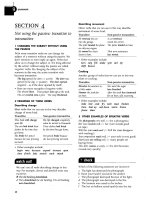
Fig.
5-10.
On the lefi, a fiont
view of the forge showing its
door and hardware, but not the
carrying handle. On the right,
a
cutaway view of this half of the
forge shows the door inset in the
forge, trapped between the fiber
blanket and a
"U"
shaped
bracket. Short SS wood screws
pin the fiberboard door to the
bracket. Rigidizer will strength-
en their hold on thefiber.
17.
Curing the forge
The forge must be left to air dry for several days in warm weather in order to give
most of the water content in the ITC
#I00 time to evaporate from the ceramic fiber
blanket. Even after the interior looks dry there is some moisture content still trapped
in the fiber lining. This must be slowly cooked out to prevent it from suddenly turn-
ing to steam and damaging the ITC
#I00 coating. After placing the door gently into
its recess, prop something that can withstand heat on either side of the door. This is
a precaution against the exhaust gasses blowing the door out of the opening and
damaging it.
Run the forge on the burner's lowest stable setting for five minutes, and then shut
the forge down allowing it to cool. Do this four times. The fifth time run the forge
up to orange hot inside, then shut it down and allow it to cool completely. Finally,
Gas
Burners
5
run the forge for thirty minutes at orange hot, then run the heat on up to yellow. The
forge is now properly cured. Remember to use the flat washer and choke to protect
the burner from forge heat even during curing sessions (see Maintenance and
Operating Instructions).
After a few days the burner is partially withdrawn back into the ceramic fiber
blanket about one inch to help protect its nozzle from the forge's high interior tem-
peratures. The collar is sealed at this time by installing the ceramic fiber blanket
shreds within the burner collar between the thumbscrews and the flat washer.
Finally, the remaining area surrounding the collar opening and the one inch of
exposed ceramic fiber blanket beyond the nozzle are coated with ITC
#
100, and the
curing procedure is repeated. This is done to keep the burner from destroying the
Ceramic fiber blanket at the burner opening. Presoaking the area in
Rigidizer is high-
ly recommended.
18. Using the forge to build exterior parts
Being a movable part, the forge door needs some support and a method of locking it
into place. With the door gently propped closed on the forge, heat and form some of
the flat bar into a
"U" shape the hard way.
The flat bar will be hammered around the horn of an anvil, leaving a generous
amount of excess length in the straight ends. If you don't have tongs to hold the flat
bar for hot work, use the
locking pliers. If you don't have an anvil yet, suspend the
area to be bent between two supporting pieces of metal and hammer on the unsup-
ported middle section while moving the work piece around until the "U" shape is
made (or hot bend it around a pipe.)
Flatten the
"U" when it's cold and drill four to six equally spaced holes for SS
wood screws. Although the screws will tear out of the refractory quite easily in the
beginning, after a while the ceramic fiberboard will take a set around them, and they
become firmly anchored in it. The screws are optional since the door will stay put
even without them.
Center the "U" on the door and mark the straight sections for cutting, leaving
them about 112-inch away from the door's bottom edges and remove the excess
stock. Form an
"S" shape from flat bar, and attach it to the top of the inverted "U".
Cut a two-foot piece of flat bar then bend and weld it positioned vertically on the
shell top and aligned with the "S" shaped bar.
Drill a 13164-inch hole through both bars while they are pressed together. Tap the
forge handle bar for a 114 x 20 thumbscrew and drill the hole in the
"S"
out to 5116-
inch. The fiber blanket has a good deal of spring to begin with, but it will shrink back
under heat and pressure so that the board moves further in. The door support will
have to be adjusted several times in response to this tendency. Finally the door will
fit firmly in one place. Once the position is reached, paint the rest of the fiber blan-
ket with ITC
#
100 to within 118-inch of the board.
Fastener assembled version
The exterior parts are bolted and screwed to the forge shell of this version. Chapter
A
Propane Bottle
Gas
Fired Forge
8
has a fastener assembled furnace, with a different method for fastening the burner
collar; supplement your understanding by reading that section.
Supplementary Parts List:
(1) A dozen 6
x
20
x
314-inch self-drilling sheet metal screws
(2)
A
1 112 NPT locking nut
(3)
Replace the
1
112-inch x 3-inch long pipe with a pipe nipple (same size)
(4) Four 318-inch locking washers
(5)
Four 318
x
16
x
314-inch bolts (no shoulder) See Chapter
9,
step
7
for a threaded
alternative.
Supplementary Tool List:
(A) One 318-inch drill bit
(B)
Two
1
1164-inch drill bits
19. Making and attaching the burner collar
Begin by cutting off one threaded end of the pipe nipple you will be using for the
burner collar. Its other threaded end will be screwed into the
locking nut, which can
then be secured to the shell with the self-drilling screws through
1 1164-inch holes
made near its hex points.
The under-side of the nut is ground into a concave surface to match the curved
side of the forge shell and the weld seam is ground flat in two places where the nut
overlaps it. The nut can be held for grinding by first screwing it down snug on the
pipe nipple and grinding away the protruding threads. Using the angle grinder to
dish out a concave shape isn't hard. The blade is held at a low angle to the work so
that its curved outline is depressed into a larger diameter, matching the larger diam-
eter of the shell. How much angle, is found by trial and error. Frequently checking
the nut against the shell will allow a near perfect fit after a few minutes of grinding.
If you want the burner collar placed at an angle, then the concave face is tilted to
one side. The amount of grinding and checking is almost the same. Just make a mark
in the center of the
kiln shelf and use it as a target. The pipe nipple then becomes
your "site" for lining up the burner's aim. The aim doesn't need to be perfect because
Fig.
5-1
1
On the lefr, a burner
collar and close nut. Note the
holes for self-drilling screws
near the nut's corners. On the
right, two views of the tapered
and curved nut.
Gas Burners
5
the burner can be re-aimed using the thumbscrews. Grind a taper on the bottom face
of the nut, leaving it 3116-inch thicker on one side than the other and continue with
grinding the concave surface as previously recommended.
2O.Attaching the legs
Follow the directions in Step 8, but mark the leg positions by inking the hexagonal
outline of the coupling nut where it touches the forge shell. Then, mark cross-lines
from the hex points and center punch. Drill pilot holes and then enlarge them to
318-
inch. Attach the coupling nuts using the short bolts and locking washers. Lock them
down tightly. Remember that you won't have ready access to retighten them later if
they should loosen up. If you decide to braze the inside bolts in place, be sure to
remove their zinc layer where you want the braze to adhere. Also, carbon-black the
thread to make sure the braze doesn't stick to it.
2
I
.Attaching the door parts
Use two bolted on handles if you place the burner collar at top dead center. Also use
four small curved flat bar braces fastened to the forge body by sheet metal screws to
hold the door in place instead of the
"S"
shaped part and thumbscrew. Otherwise fol-
low the previous recommendations. The forge handle is built in a "U" shape about
one foot long and four inches high. Drill two 11164-inch holes in each of the bar's
ends. Then, bend the ends at
9O0angles (about 1-inch long). Use self-drilling sheet
metal screws to attach the flat bar handle to the forge body afterward. Hammer the
ends down to match the shell's curve.
22.
Advanced design options
The first desirable option is a special mounting plate for the shut-off valve. It can be
placed either on a forge leg or on the side of a wheeled cart that the forge and the
propane bottle sit on, along with the hand torch on its own burning lead.
A 318-inch or 114-inch copper tube runs from a valve on the plate up to the burn-
er. The first advantage here is safety because the fuel hose is kept well away from the
hot forge shell. The second advantage is that it provides a stable platform for idler
assembles (see Fig. 5-14).
Before deciding on any of these options, remember that you must check with
your local fire department and check the building codes for your area, in order to
determine safe and acceptable practices. Local authority modifies many of the rec-
ommendations in the Gas Code. What is considered acceptable practice in one place
may not be approved in another.
An
idler normally uses two valves in parallel, a ball valve and a needle valve. The
ball valve acts as a shut-off when the needle valve is completely closed. However, with
the needle valve open a little way, the ball valve becomes a
kind of highllow switch.
When the ball valve is closed, a lesser amount of gas is allowed to escape through the
needle valve to keep the forge running at an idle while you're busy working the part.
Then the ball valve can be quickly opened for full heat when the part is again placed
within the forge. This will save a lot of fuel and help to keep the shop more
comfort-
A
Propane Bottle Gas Fired Forge
Fig.
5-12
A close up view of the double
valve idler assembly with a ball valve in
the upper middle of a copper tubing
manifold and the needle valve below it.
The upper left side shows the gas exit
tube leading to the burner. The upper
right side shows the threaded gas
entrance ready to be hooked up to a fuel
hose. Note that both sides of the needle
valve and the left side of the ball valve
have nuts that can be unscrewed with
the manifold in place. This allows the
valves to be changed out or serviced.
able in warm weather. The needle valve can be set higher or lower to keep it synchro-
nized with different full heat pressure settings on the forge. The disadvantages of this
arrangement are the complicated plumbing involved in
making a miniature gas
manifold and the possibility of the
packing in the needle valve leaking. The main
advantage over a mechanical idler is fine-tuning. It is also the standard practice.
Fig.
5-13
shows an example of the many ways there are to set up the two valves.
The main thing to be remembered when building your own version, is to make sure
you leave room for the fittings to screw completely off so that the valves can be
cleaned or replaced if necessary.
Fig.
5-13
On the left, a detail of the
coupling nut welded to the back side of
the idler assembly plate, with a locking
nut above the plate's top edge. The cou-
pling can be welded brazed or screwed
on, and its thread chased with a tap. On
the right, a section of the forge with the
assembly mounted on a leg. At its top, a
copper tube heads toward the burner. At
bottom, an elbow holds the fuel hose
just above the head of the carriage bolt.
It is wise to employ a protective cover on
the hose for a couple of feet. Gas mani-
folds should never be mounted on the
heated forge shell, but rather on a leg or
on the side of a cart.
Gas
Burners
5
Brazing the manifold together with all the parts in place is the easiest way of mak-
ing sure everything will fit. In order to protect the valves from heat, open them fully
and partially submerge them in water (remove the handle from the ball valve during
soldering). This method forces you to clean and prepare the two sides of the mani-
fold separately, and then braze them in two stages. The control gained is worth the
extra effort. Remember to blow-dry the manifold afterward (see Fig. 5-16).
22.
Single ball valve idler assembly
When a ball valve is mounted on the burner, it is only used as a shut-off. By mount-
ing the valve on a separate plate and having the valve handle rest against a movable
stop, it can also become an idler valve.
To make this assembly, you should start with a larger size valve than you would
use if it were mounted on a burner. The point here is that the bigger valve will have
a larger handle and a stronger valve stem. The valve is mounted on a steel plate by
trapping it with steel
"U"
bolts.
A
small bolt, with it's head cut off and replaced by a piece of flat bar for a handle
(or part of a small
"C"
clamp as shown in fig 5-14) runs up and down in a slot.
A
nut
and washer on the bolt force the movable plate on the backside up against the
mounting plate to lock the bolt in position. With the bolt loose, the back plate moves
Fig.
5-14
The mechanical idler
assembly is displayed in front
and top views on the drawing's
lefi side. The valve handle rests
atop the threaded
handlefiom a
"C"
clamp. The top view shows
how the locking nut presses a
sliding plate tightly against the
back of the mountingplate, lock-
ing it in any desired position
within the range allowed by the
slot. On the lower right side is a
detail showing the slidingflat bar
trapped between two perma-
nently
afied square bars. On
the upper right side, the four
moving parts of a movable
mechanical stop are shown.
A
Propane Bottle Gas Fired Forge
vertically, while the two square bars prevent it from spinning. This provides a mov-
able stop for the valve handle, allowing the idle setting to be adjusted so as to be ade-
quate for different full pressure settings. The mechanical stop is dropped to the bot-
tom of the slot when shutting down the forge.
No sizes are given, because everything is dependent on the valve size. I would sug-
gest a three-inch "C" clamp for parts though. Once you have everything adjusted on
the sliding arm, drill and pin the nut or silver braze it to keep it from moving. Also a
double nut arrangement can be used to lock the nut in position.
Using a ball valve in the partially open position is not considered good practice
because the valve can degrade from wear as the gas moves past it. However, you are
only running a few pounds pressure on a regulated system. Parallel valves are consid-
ered the correct way to do the job. The choice is yours, but you need to check with
local authority to see if either method is allowed in your area.
The tube can be made adjustable by running it parallel to the curve of the forge
shell a ways and then bending it upward to make a giant
"L"
shape. The point is to
deliberately provide excess tubing so that the burner can be moved up later (see cur-
ing the forge section). This also prevents any possibility of temperature changes or
physical stress causing the gas connections to be loosened. Make sure the tubing is
kept about two inches away from the forge body in the parallel section of the run (to
avoid heating the fuel).
Use compressed air to blow any metal shavings or dirt out of the copper tubing
before final installation. Blowing out the internal parts can be accomplished without
the use of your own air-compressor. You can use a bicycle pump. In order to do so
you will need an adapter, but there is no need to make one. Just go to an automotive
tire store and buy a tubeless tire valve stem.
Fig. 5-15 The plastic cap over the thread and air valve is
shown
haycut away. The bulbous protrusion on the other
end is hard rubber. This is a typical tire valve. The valve
itself uses a
1/8-inch standard pipe thread on one end
and a standard spring-loaded internal air valve. It is
called a tank valve when sold without the outer rubber
covering.
A
tank valve will screw directly into the end of a
standard air blower
ifyou wish to employ it that way.
It has a rubber base to seal against different part shapes, a plastic cap to protect
it from dirt, takes up almost no space in your toolbox, and is inexpensive. Remember
that any metal shavings will be blown out of the tubing at high speed, so be careful
about where it is pointed. Do not use the compressor at a gas station with this tool,
because there are no vent holes beyond the rubber face of the stem. It will deliver full
pressure to the part and thus does not meet safety standards.
Copper tubing with flared or compression fittings has been considered standard
practice for connections on the low-pressure side of regulated lines in the past, but
you must check with your local authorities to make sure they are still approved in
Gas
Burners
5
your area. Further, you must find out which one of these two types of fittings your
local codes call for.
With the forge mounted on top of a handcart, you should build hangers inside
the cart to store two coiled fuel hoses. Buy a "T" fitting and install it on the forge cart.
Run the copper tubing from one opening up to the forge, and the other openings to
the fuel hoses.
The regulator is kept on the fuel cylinder and is linked to the cart by one of the
fuel hoses. When the forge is used, after transport to a job site, the tank and regula-
tor are brought out of the cart and placed at a distance from it.
The other fuel hose has the 112-inch hand torch connected to it. It can be used to
light the forge and preheat the anvil while most of its lead is left coiled in the cart.
When it is being used for silver soldering or tempering the whole line can be uncoiled
so that the cart may be left at a distance, and the tank may remain in the cart on a job
site.
Black propane hose is not very flexible. This makes it a poor choice for use with
the hand burner, but standard burning leads are not rated for propane. However, for
about $4 extra you can buy burning leads that are a rated for propane. These two dif-
ferent kinds of burning lead look exactly alike accept for the identification letters
printed on the hose. Make sure to ask for the propane rated type.
Once the brass collars are removed from the ends of the lead, the oxygen hose will
easily peel away from the fuel hose. The oxygen lead can be saved for use as a com-
pressed gas lead for welding machines or for use with an Oxy-fuel torch and propane
gas. The fuel line can be hooked up to a fuel-to-pipe fitting connector on the "T" fit-
ting to be used with the hand burner. Since the burner leads are about 25 feet long,
you actually end up paying no more per foot than the regular propane hose would
cost.
The proper procedure for safely starting and running the forge:
(1) Make sure the burner valve is closed and the burner choke is part way open.
(2) Open the tank valve completely.
(3)
Open the regulator to six PSI.
(4) Ignite the 112-inch torch or a small portable propane burner and insert the flame
well inside the forge opening. Aim the burner at an angle and keep your hand out of
the path of the hot exhaust.
(5) Open the valve to the burner, but keep your hand on it. Sometimes you won't get
an immediate ignition. If you don't, close the valve but keep the flame inside the
forge. Reopen the valve and try again. You could repeat this procedure frequently
without danger from gas build-up.
(6)
Extinguish the hand torch by closing the ball valve that feeds gas to its fuel hose.
This allows the positive pressure to equalize with ambient air until the flame snuffs
out; then close the valve on the burner.
(7)
After ignition give the forge a minute to warm up then completely open the burn-
er choke and set the gas pressure wherever needed to do the work. Remember to keep
the pressure high enough to get a complete burn. When using the idler system, the
A
Propane Bottle Gas Fired Forge
forge should still be kept running at high enough pressure so that the exhaust flame
is no longer blue.
(8)
Wear
UV
protection. With these burners, your forge will turn an incandescent
yellow-white at higher gas pressures. This creates the danger of flash burn if you peer
into the forge without dark glasses. To determine how dark is sufficient, close your
eyes after looking. If you get an after-image, the glasses aren't dark enough. If you
spend much time looking into the forge you're going to need a darkened face shield
or sunscreen ointment to protect your skin. It is best to use your watch and time the
heats instead of checking the work visually.
(9)
Make certain the forge is properly secured to prevent it from being knocked over
while it is running or during cooling.
(10) To safely shut down the forge, close the tank valve completely, then wait for the
burner to run down and go out. As soon as this happens, close the burner valve and
shut the choke completely. Failure to shut the choke will result in heat damage to the
burner from hot gases backing up from the forge and exiting through it.
(11) Finally, back the regulator off completely (turn the pressure adjusting screw
counter-clockwise until it moves freely). This leaves the whole system with an atmos-
phere of propane in it (so there is no need to purge it), but without positive pressure.
Wait until the forge cools down completely, and then double check the valves to make
sure they are closed, before leaving the area.
(12) Never leave a forge or torch running unattended.
Tuning
the
forge
Once the forge is warmed up, the exit flame should have a yellow color. Blue flame is
a sign of incomplete combustion. If your forge doesn't normally show blue flame,
than you are most likely running it too low and should turn it up. If this has no effect,
remove the burner and check it for obstructions (especially the gas accelerator ori-
fice).
If the blue flames are a constant problem, widen the forge openings. Remember
that the venturi effect is not a strong force. If you bottle up the exit gasses, you can
force the burner to run a reducing flame just as though you had made its air slots too
small. Once the burner is installed in the forge, you must think of them both as one
system.
The exhaust gasses are spinning and expanding as they leave the forge. This
means that some of the spent gasses are already leaving the forge at close to right
angles. It takes only a mild breeze to bend their trajectory a little more, thus feeding
some of the oxygen depleted gasses into the burner intakes. When working outside
or in a drafty area, position the forge to avoid this. If it starts running erratically, shift
its position or shelter it from the wind.
During the drying process it isn't surprising to experience interference from
water vapor. It can even blow out the burner flame. Encountering the problem again
after long periods with the forge sitting idle in a damp climate can also be expected.
Even with the forge running fiercely, you can place your hand in front of the
exhaust as little as two feet away. This is because hot air rises and is not due to the
Gas
Burners
5
heat dissipating in that distance. If you raise your hand, it will burn. The point is that
appearances are deceiving. You can't see the super heated gasses rising, and you won't
see a wooden wall being dangerously dried out from the forge running a few feet
away from it. Nevertheless, both of those things are happening. If you don't protect
the back wall and ceiling it can suddenly explode into flame without any period of
smoldering first.
Maintenance
Most of this section was covered directly or by implication in various sections previ-
ously. It is necessary to keep the burner entrance sealed as much to protect the parts
being forged from oxygen infiltration as to isolate the burner air intakes from spent
gas during operation and to stop the chimney effect after shut-down.
It is important to avoid overheating the burner nozzle. This requires the nozzle
placement to be recessed about one-inch back into the refractory lining in order to
shelter it from the high interior temperatures of the main forge chamber. It means
keeping a watchful eye on the burner nozzle to make sure it isn't being overheated
sagging out of shape or burnt up.
A
sudden shower of very fine sparks coming out of
the forge exit is a danger signal which may indicate one or both of these occurrences
in progress. If you run your forge high enough to encounter these problems, you
need to consider switching to a boron nitride coated mild steel nozzle or the use of a
ceramic burner port.
Obviously, gouges in the ceramic refractory lining or end enclosures must be
repaired immediately. Cracked kiln shelves should be repaired with bonding mortar
or replaced if needed.
The forge should be sheltered from the weather. If it can't be stored in a warm dry
place, consider wrapping it (when completely cooled down) in a watertight tarp.
Dampness is bad for every part on and in the forge. If the forge does get wet, use the
same formula to dry it out that you employed to cure the refractory coating in the
first place.
Building
a
Forge Cart
The forge cart was originally designed just for convenience in storage and handling
of a portable forge; however, it became clear that many smiths did not consider a
tube forge
sufficiently flexible to replace their open coal forges (the tube forge is fea-
tured in Chapter
5).
There was also a great deal of interest in the refractory tabletop
as a movable hot-work surface for metal and glass artists. Since the cart is an obvi-
ous platform for temporary brick heating structures and clamshell forges, it has been
designed to become a mobile hot-work station. You may decide not to build all the
following features. Even so, the cart's general construction will provide a good plan
to follow; just delete the features of no interest.
Fig.
6-1
Even without forges
mounted this cart is a general
hot-work station. Note the depth
of
insulated tabletop, from
which the flame emerges.
Gas
Burners
6
The cart uses 118 x 1 112-inch angle iron for its frame because that size provides
sufficient strength without excessive weight. Angle iron lends itself well to this kind
of construction and it is the most economical of steel forms. The sheet metal for the
shelf bottoms can be steel or aluminum. It should be heavy enough gauge to support
the load to be placed on it. The sheet metal in the tabletop's sidewalls should be steel.
Aluminum sheet metal could lose its temper (and thus most of its strength) near the
hot brick face. Aluminum is a better choice for the shelf bottoms. Tempered alu-
minum and mild steel run about even pound for pound in shear strength but the
greater cross section of the thicker aluminum plate provides better rigidity.
This cart is shown fastener assembled, but can be welded together. It is three feet
long, but the forge faces across its length because the exhaust gasses would otherwise
heat the tabletop and any accessories mounted on the cart. Space between the two
types of forge is used to rest hot parts or to do silver brazing and heat coloring. Both
forges can be removed and more insulating bricks can be stacked into temporary
heating structures on the top shelf in order to accommodate the occasional piece,
which is too large to be contained within the portable forge. A clamshell forge can
also be attached to the tabletop.
The cart's refractory top has a throughway for the vertical burner collar. The table
also segregates the forge and hot work from the hoses, which hang a few inches below
the top shelf, protected from physical damage by the cart's frame and expanded metal
screens. The tank is taken out of the forge cart during operation and moved to the
minimum safe distance from the forge required by governing codes. OSHA requires
a minimum of twenty-five feet. Other codes require the tank to be placed outside of
enclosed spaces. The tank and regulator are connected to the rest of the system by
their own hose. Don't leave the tank in the cart when the forge is in use or when the
cart is stored inside.
Read this entire chapter before you start construction; then decide if this size is
going to be sufficient for all of the accessories you want to build. Simply adding any
desired width to the existing dimensions would increase the length and width of the
cart. An example would be an increase from the nineteen-inch width to two feet. Part
#
9 would increase in length from 18 112-inches to 24 1M-inches. So the materials list
can quickly be adjusted to reflect a dimensional change. All 19-inch plus angles are
width, 40-inch angles plus are height, and 30-inch plus angles are length. The same
holds true for the shelf materials.
Item
#10 is used for the legs. This cart is designed for two-inch wheels and the
comfort of a six-foot person. Larger wheels and shorter stature should be subtracted
from this figure. The length and width dimensions given, work out well with the
standard brick size chosen. So, if you change the dimensions the keep brick sizes in
mind. The ability to transport a cylinder inside the cart is less important than com-
fort when using this equipment.
Materials
list:
(1)
Three cans of red polyurethane spray paint and one can of black barbecue spray
paint
Building
the
Forge
Cart
(2) "T" fitting, (refer to Chapter 2), two ball valves and other parts required to make
the fuel hoses work
(3) One 114-inch type
"T" Oxy-fuel hose
(4) One type regular propane hose long enough to allow it to hook up to a cylinder
stored outside
(5) 114-inch copper tubing, about 4-foot length.
(6) Two swiveling castor wheels and two rigid castor wheels (see Resources)
(7) Six 118 x 1 112 x
1 112-inch steel angles, 35 314-inch long
(8) Six 118 x 1 112 x 1 112-inch steel angles, 18 314-inch long
(9) Two 118 x 1 112 x 1 112-inch steel angles, 1 112-inch long
(10) Four 118 x 1 112 x 1 112-inch steel angles, 40-inch long
(12) Two 118 or 3116-inch x 1 112-inch flat bars, 29 314-inch long
(13) One piece of 3116 x 18 112 x 35 112-inch aluminum sheet
(14) One piece of 3/16
x
18 112 x 39-inch aluminum sheet
(15) Two pieces of 16 gauge expanded and flattened metal 24 112 x 35 112-inch
(16) Two pieces of 16 gauge steel sheet metal,
6
x 35-inches
(17) Two pieces of 16 gauge steel sheet metal, 6 x 18-inches
(18) One box 3 112 x
4 112 x 9-inch insulating refractory bricks
(19) Small sack or a gallon pail of air setting refractory mortar mix (see Step 9).
(20) 1 x 18 x
%-inch calcium silicate board or alumina fiberboard
(21) Fifty count boxes of
#lo-32 x 314-inch machine screws, washers, two boxes of
nuts, box of self-drilling screws (close to the same size)
(22) One cubic foot of Perlite
(23) Brass shower drain
(24) Steel or SS tube to match the ID of the shower drain and 4 112-inches long
(25) 2 x 314-inch threaded reducer
(26) Four 1/4-20 thumbscrews, 1 112-inches long
(27)
#8 or #10 set screw
(28) 3 linear feet (forty-two inches) of one inch thick, 8
#
ceramic fiber blanket
(rated for 2300" F) from a 24-inch wide roll. Or 1 112 linear feet of two inch thick.
(29) Mullite tiles are recommended as a hard facing instead of the soft insulating
brick. They should not be less than
1/4-inch thick or more than 518-inch. The
Perlite layer allows for adjustment to thickness.
These materials make a strong special purpose cart. If the cart is going to travel
a lot, then it might be worth your while to redesign the tabletop with lighter prod-
ucts
(i.e., alumina fiberboard and rigidizer coating). Likewise, the steel can be
replaced with aluminum and the standard wheels with lighter kinds. A busy shop
owner might replace the cart completely, with a portable stand such as are popular
for cutoff saws if the forge is mainly planned for field use.
Tool
list:
(A) Electric hand drill with three 3116-inch drill bits, 13164-inch bit, a
#
3 bit,
and a 112-inch countersink
(B)
A
4 112-inch right angle grinder (cutoff wheels recommended)
Gas
Burners
6
(C) Welding machines are the practical way to do this much work; however, this cart
is set up to be drilled and bolted together
(D)
A
#lo-32 starting tap and #21 drill bit, 114
x
20 starting tap, tap handle, tapping
fluid
(E)
6-foot tape measure, 12-inch combination square, ink marker, and scribe or
soapstone
(F)
Three 3-inch C-clamps (recommended)
(G) Small center punch or prick punch
(H)
Safety glasses
(I) 2-foot carpenter's square
5
(J)
Cheap 1-inch paintbrush
(K)
A
3 112-foot pipe clamp or furniture clamp
(L)
Jig saw (recommended)
I
.Assembling the shelves
Fabrication of the cart begins by assembling the top shelf. Cut both of the ends back
at an angle of
45"
on one flange of each of the shelf angles (one pair of the parts #7
and one pair of the parts #8). Next, deburr them and lay the parts out in a rectangle
(toe in and toe up). If you aren't familiar with these terms, look them up under
"Angle" in the Glossary. The second pairs of parts
#7
&
#8 will be cut differently for
the bottom shelf.
Fig.
6-2.
The inside of the angle corner as seen
looking down into it, is shown in the upper
right corner. To its left, the
45"
cutback in one
flange of the angle, which is viewed toeing up
and in. Bottom right is an outside view of the
corner, looking up at it. To its left, the angle is
in perspective looking down. It is now toed up
and in. Note that the
45"
cut does not form a
complete point. It stops short of the other
flange, creating a space in the vertical portion
of
thefiame corners. The opening allows them
to clear the web's radius on the inside of the leg
I
Check them for parallel by comparing the width and length measurement at
either end. Grind the cutbacks to adjust sizes. Then, check for square by measuring
from one corner diagonally to the other (farthest) corner. Then make the other diag-
onal measurement. When the two measurements are equal, they are square (this is
called
"X"
pattern squaring, or crisscross squaring). Tape around the upright sides of
the corners in order to hold them in position and place the 18 112-inch
x
35
112-inch
piece of sheet metal inside them. Center the sheet metal and clamp the work in place.
Use a clamp on each of two diagonal corners and double check the work with a car-
penter's square. Then do the same on the other two corners.
Building the Forge
Cart
Screw the sheet metal to the angle frame about every six-inches, ending about 1
112-inch from each of the angle ends. Check carefully as you fasten the angles to the
sheet metal to make sure they aren't drifting out of square. Begin by fastening one
side of a corner and do the same in the diagonally opposite corner (checking for
square as you go). Then, follow the same procedure for the other two corners. Next
check your outside dimensions and fasten all the other angles at their corners. Now
install the rest of the screws.
Fig.
6-3
The assembled shelf;. note how the
corners are not closed, thus allowing a tight
fit between them and the vertical angles
which will become the cart's legs. Also note
what appears to be an
"L"
shaped line of
dots. These are the screws which are along all
sides of the sheet metal that covers the shelf's
bottom.
2.
Constructing the legs
The four legs are completely finished before they are mounted. This is done in order
to assure that they will all end up extending exactly the same length below the cart.
If anything goes wrong with this plan, they will still end up close enough to be evened
out with the addition of flat washers between the holes on the angle iron's
"tab" and
the castor's mounting plate.
Fig.
6-4
A pointed
1/2
x
6
bolt and flat bar part with
hole drilled in its center to be threaded for the bolt, along
with two holes for machine screws on either side of the
main hole. Mount the two bolts near the outer edge of the
lower shelf; and far enough in to clear its swivel wheels.
Attach
theflat bars with their center holes drilled but not
threaded. Drill through the aluminum plate and angle
and then thread all three parts in position. This provides
enough thread depth to secure the bolt.
2-inch cast iron wheels are ideal, but hard rubber castor wheels are good enough
for the cart (do not use pneumatic tires). If you drop something hot against one of
them, just nudge it away. You need rigid (non-swiveling) wheels on the forge end of
the cart and swiveling wheels on the far end. If you can get two locking wheels for the
swivel castors, then you don't need to build mechanical stops. Otherwise, use two
short pieces of thick flat bar, drilled and affixed to the lower shelf. Then run thread-
ing through all the parts to match the long bolts. They act as breaks when screwed
Gas
Burners
6
down to touch the floor. Any metal will do for the flat bar. You will have to add the
bolts, a drill, and a starting tap for them to your supplies.
Buy castors that have a flat mounting plate at their tops, which can be bolted to
the angle legs. Cut away one side of the angle, equal to the length of the castor
mounting plus an extra 112-inch for the bend's radius and the web's thickness. Grind
a notch in the cutback side to help the long side bend more tightly when folded over
it. Use a cutoff wheel as your saw blade. Cut above the web on all four legs and grind
them flat afterwards with a regular grinding wheel. Remember that you have a left
and a right facing leg on both ends of the cart. So, when you cut away the flange on
one side of the four angles, you must end up with two lefts and two rights.
Fig. 6-5 Two angles are cut "left hand" and
'fight hand." It isn't important which is
which. Just remember to end up with two of
each kind among the four cart legs.
If
you
imagine their extensions (tabs) bent up at
909
they would be in the same position as
they are used on the cart. Castors are mount-
ed even with the outside of the angles with
any extra castor width kept under the cart, as
in Fig. 6-6.
Fig. 6-6 The extended area left on the uncut
flange is bent over to make a mounting face on
the leg bottom. It ends up longer than the width
of the flange it rests against, but the extensions
on the castor's mounting plate (which hold the
wheel axle) help maintain rigidity. Two mis-
matched holes have been relocated to fit within
the flange's width. Note that the overhung sec-
tion will end up under the cart.
Afterward, heat the tab in the forge and bend it over the short side. There is no
need to braze the seam. Drill and thread matching holes in the folded side. Then, bolt
on the castors. If the castors you choose have a wider mounting plate than the
1 112-
inch angle can cover, drill a second set of holes in the middle of the castors mount-
ing plate and the tab. Assemble the castors with the excess width positioned under
the cart. It is important for the castor to sit square on the leg end, at least in the in
the direction that is parallel to the wheel axis. Otherwise, the wheel wouldn't sit flat
on the floor. Hammer, and grind the angle tab as square as you can using washers for
shims if necessary.
After all castors are mounted, measure the length of the legs from the wheel edge
Building
the
Forge
Cart
Fig. 6-7 The vertical angle of a leg extends
several inches past the two horizontal angles
of
the top shelf: Note that only two of the four
screws are put in place until the cart is
squared, and then the others are installed as
Fig. 6-8 The completed
fiame, with wheels and top shelf; is now
shown. Your angles may run a little high
ready for addition of sheet metal sidewalls and top angles. This is
and/or low as you adjust leg heights in order
thefirst opportunity to correct any out of squarefitting. The cart
to make all the legs the same length below the
while be semi-ridged after the installation of the sheet metal, but
shelf bottom. Fig. 6-10 shows the quick and
installation of the screens and bottom
shelfwill provide a second
easy solution to this possible problem.
chance to further refine the squaringprocess.
to the far end of the angle with the aid of a square. Cut the angles down to the meas-
urement of the shortest leg. Drill two holes in each flange of the four angles. The
upper holes are drilled at 112-inch from the cut end and 112-inch in from its edge.
The lower holes are drilled at
1 114-inch from the cut end and in the center of the
flange for later use
3.
Mounting the legs, braces,
and
shelves
Use the square and temporary brace just as you did to keep the shelving rectangular.
Measure
6
112-inches down one leg. Clamp it to the side angle (longest dimension)
of the top shelf. Check it for square and fasten it with one screw. Clamp a leg on the
other corner (long dimension). Clamp an angle (toe in and toe up), 1 112-inch above
the wheel mountings, on the inside faces of the angle legs. Cross measure for square
and fasten two screws on all four corners, this side only. Turn the cart over and repeat
the process, but only use one screw in each corner of these legs and bottom angles.
Remember to use rigid casters on one-end and swivel castors on the other.
Check the second aluminum sheet for square and parallel before resting it at an
Gas
Burners
6
angle with its lower edge centered between the cart's legs on the rigid side. Transfer
the placement of the leg's flanges to the sheet with a scribe (inside and outside faces).
Drill holes at 1 114-inches in from the slot edges, and grind or saw out the remain-
ing material. Place the sheet inside the leg's flanges, and repeat this process on the
other set of legs. First, double check to make sure the cart is remaining square. Clamp
a bar across the end side of a set of legs, check for parallel, and fasten the sheet to that
end. Repeat this procedure on the other end and then fasten the sheet about every
sixth inch.
Now place and fasten the end braces to the bottom side the sheet, toeing out and
toeing down. Fasten the braces to the sheet and legs.
Stand the cart upright on a flat surface and inspect it for overall fit-up. Adjust the
cart's fit with washers to obtain the best compromise possible for overall perform-
ance then fasten the rest of the screws. You will have a further opportunity to adjust
the cart in one direction once you install the sidewalls and screens.
4.
Installing the sheet metal side walls
Lay the cart on its end. Clamp a 6 x 18-inch piece of sheet metal inside of the verti-
cal angles and check the cart for square. The sheet metal is supposed to end up about
114-inch below the tops of the vertical angles. Drill holes every six inches (in the
ten-
ters of the angles) and secure the sheet metal with screws and nuts. Grind off the
excess thread inside the vertical angles. Flip the cart over and repeat this process on
the opposite wall. Then do the two sidewalls. Remember to check the cart for square
before installing the four sidewalls.
5.
Making and installing the top angles
Begin by clamping a string tightly between the tops of two diagonal leg angles. Clamp
another sting to a third top and stretch it tightly, crossing over the first string, and
bringing it down on the fourth angle top. If the two strings fail to touch, your tops
don't represent a flat plain. If the strings bend each other more than one string' thick-
ness, they don't represent a flat plain. By raising or lowering one corner, you can
establish a flat plain. When your horizontal angles are installed this same method can
be used to avoid building a twisted tabletop.
These angles toe down and in. They are fabricated so that they can be removed
singly or all at once. This is a convenience during construction and later on when and
if the bricks are mortared into a solid surface.
Cut a piece of angle the same length as the overall outside dimension of one long
wall (minus the thickness of two flanges). On each end cut one flange back about
1
9116-inch, and grind the web section of the flange flat.
Slip it between the vertical angles and clamp it to the sheet metal wall with its
other flange resting even with the tops of the vertical angles. Then mark the other
flange on each end at a
45" angle, using the heel (outside corner) of the vertical angles
as your starting point. Make the two cuts and install the angle with self-drilling
screws. On all of the top angles the excess screw thread must be left in place.
Complete this step on the other three walls.
Building the Forge
Cart
'~*
~' ,
',\
' ,
C
**.
'k.
4
1
:+-%,,J
.,
1.
.
-,
,
Fig. 6-9 End cut of horizontal top angle;
Fig. 6-10 Detail of top corner construction. On the
note that theflange with the
45"
clearance
left side of the leg, the sheet metal side wall is kept
angle is cut
08
short of the web, so that
below the height of the web's radius. The top angle
after grinding the other
legflat, the hori-
isn't installed on this side yet. The right side of the
zontal angle will rest even with the top of corner is complete.
the vertical angle, without reference to its
height. Note also the web radius remain-
ing on the vertical flange. This is the rea-
son that the sheet metal is cut so low.
6.
Mounting the screens
The fuel hoses should be enclosed for protection. By employing flattened expanded
metal instead of sheet metal for the cage, the equipment stays visible and open to the
air while being isolated from hot metal parts. The screens are placed on the two long
sides of the cart. There is no screen on the ends. The coiled hand torch hose is stored
on a rack in the open space below the forge. The screen is mounted by trapping it
between the flat bars (parts #16
&
#17) and the cart's frame with screws and flat
washers.
Cut each screen into a rectangle large enough to cover a side face from the bot-
tom of the lower shelf to the toe of the top shelf's bottom angle. But, keep the screens
length about 1-inch short of the length measurement so that it will easily fit inside
the legs.
Remove one leg from its corner, place an end of the screen under it, and re-install
the leg (you may need to ream out the holes in the leg's other flange afterward in
order to reinstall the end screws). It will be necessary to drill away parts of the screen
where they intersect the screw holes. Repeat the process on the other leg, making sure
the screen stays flat against the two shelves.
Drill through the horizontal and vertical angles about every six inches. Position
the screw holes next to the screen's metal parts so that the screw caps and nuts will
clamp the screens to the angles. Next, turn the cart over and use the grinder to
remove all excess thread protruding into the bottom shelf. Then, install the second
screen the same way.
Gas
Burners
6
7.
Final wheel adjustments
To further adjust wheel height use flat washers between the castor plate and the angle
face. Two of the wheels swivel and therefore need not be aligned with the cart.
Enlarge their holes and twisting them on the faceplate can realign them on the face-
plate. Or, the bent flange can be heated (with the forge burner) just above the bend
and hammered to tweak the alignment sufficiently to make the cart roll straight.
8.
Constructing the burner collar
The collar is placed at the far end of the cart away from the swivel wheels. Measure
the width of the top shelf. Place a mark in its center and the same distance from the
end wall. Measure the outside diameter of the shower drain thread and ink mark the
hole (you can use the paper washer that comes with it). Drill a pilot hole and saw out
the hole.
Sand the end of the steel tube clean, flux it, and place it within the drain
fmture.
Be careful not to put any strain of the fixture. Any stress can force the drain's thread
out of round when the parts are heated (don't hammer the parts together). Screw the
nut onto the drain. Run silver braze between the two parts. When they cool down,
you have a press fit (in effect). Use its four spanner wrench knobs to indicate where
to place the four
1/4-20
thumbscrews. Make sure the threaded holes clear the nut.
and install the burner collar.
Fig.
6-1 1.
Two views of the burner collar assembly.
98
Top angle-
Form created by a
f.:
.,
small garden pot
1.
';
1
.
-
-
/*
.'
1;.
.> I
.
.
, ,- -,
,
.
+I,.
*;:
-
Insulating brick
-,
.
;:.:;;;;:;;;'
.
,,
-, ,.
,,
.
,
t
, ;:;;.r;,
;
-
,
,
.
' ,
.>.
-:5;,
!r.;
>>
:,,
'C
.K-'
'.
fi.: *
i;,:.;:
.
?
d.
.,
,c,
?
.:7;
; I
,,~,,;+~:!.
.:,,:.;i,
Castable
r:!?:Y
i
,
.
. .
:?'-?:!:,;
:-* ::-
r
.,
i.1
.Gi-:;.;l
,
.;:
.'
I,.
.
,D,
rj',* '.
.:*, ;
,.
,:.
;".
-
i
,",
,
.
-
.
L
Calcium silicate bo
1
I
Perlite
1
.;\
.I.
Aluminum shelf
\
Building the Forge
Cart
9.
Insulating the tabletop
This tabletop employs trapped insulating firebrick resting on a foundation of fiber-
boards. The boards float on a bed of Perlite. The insulating boards are cut and fit
closely enough to prevent the granules from rising through the cracks between them
so the Perlite will only compact far enough to adjust into a flat plane. The table's top
angle irons are toed in, locking the outside ends of the bricks in place. The oversize
burner collar extends up through the Perlite and part way through the board. A
tapered hole in the brick acts as the burner portal. This allows a variety of burner
sizes to be held in a perfect position to be used with the Clamshell Forge and tempo-
rary brick forge structures. Because the brick is fragile, it is recommended that a
square opening be left in it, and a burner port be poured from
castable refractory (see
techniques used in Foundry Furnaces, Chapter
9).
The port's orifice should be kept
1-inch larger diameter than the
0.
D.
on the nozzle of the largest burner you plan to
employ in the cart. It should be tapered. Floral cones can be stuck in the end of the
pipe as the inner form. Glass votive candleholders have a good taper, come in vari-
ous sizes, and often have a built in step. This leaves a convenient ridge for holding a
plug. After the refractory has completely hard set the glass is heated, then cold water
is poured into it. The pieces are carefully removed when the glass shatters.
Rest the fiber blanket on the bottom shelf of the tabletop and push it against the
edge of the top angle to make a depression. Cut the blanket at about 112-inch beyond
the depression and force it into place against the sidewall. Run this compressible
material all the way around the inside of the walls.
Fig.
6-12
Looking down onto
the tabletop
as
the first brick of
the second row is moved into
position under the overhanging
flange of a top angle. The posi-
tion of its outside jaw can be
adjusted on the pipe, allowing
every brick to be slowly forced
into position. Under the second
row is the
ofside seam between
the two calcium silicate boards.
Fill up the bottom 2-inches of the "trough" with Perlite. Saw the refractory to a
length one inch greater than the toe to toe (near edges) measurement of the board
top angles. Next remove one end angle. Push the board hard against the closed end
and the long sidewall to compress the blanket. You can use a left over piece of sheet
metal to "shoe horn" the board down the second end of the blanket then push it
down on the burner collar pipe to make an impression for the cut out. Saw on the
outside of the impression.