Adobe Photoshop CS4 for Photographers phần 5 pdf
Bạn đang xem bản rút gọn của tài liệu. Xem và tải ngay bản đầy đủ của tài liệu tại đây (7.74 MB, 71 trang )
Martin Evening
Adobe Photoshop CS4 for Photographers
258
Reduce Noise fi lter
The other alternative to noise reduction in Camera Raw is
to use the Reduce Noise fi lter, which is found in the Filter
➯ Noise menu in Photoshop. This fi lter uses a method
of smart noise reduction that can remove noise from an
image, but without destroying the edge detail in the picture.
Overall, the Reduce Noise fi lter is a useful one shot fi lter
that is better at reducing the noise in images that originated
as digital captures, rather than reducing fi lm grain noise
from scanned 35mm images. This fi lter is mainly designed
to target the twin problems of digital luminance noise,
which is like a very fi ne speckly grain, and color noise,
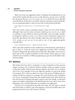
Figure 4.12
Here is the Reduce Noise fi lter being used to help remove the noise
from a digital capture which was shot at 1250 ISO, where the Reduce Noise fi lter
helped get rid of most of the noise artifacts.
259
Sharpening and noise reduction
Chapter 4
Figure 4.13
A close-up view of the Reduce
Noise fi lter settings in Advanced mode.
which is commonplace with digital captures shot at high
ISO settings. The only problem with this fi lter is that
it is quite memory-intensive, so be prepared for a wait
while it performs its calculations. Although it can appear
quite effective at removing heavy noise, if you do have to
apply extreme settings you can sometimes end up with an
enhanced noise pattern instead.
In Basic mode you can simply adjust the strength of
the noise reduction and then use the controls below that
to modify the noise fi ltering; these should be adjusted in
the order they are displayed. The Strength slider adjusts
the amount of noise reduction that is applied, while the
Preserve Details slider helps preserve the edge luminance
information. The luminance noise reduction will appear
strongest when you set Preserve Details to zero %, but as
you increase Preserve Details more edge detail (and often
more noise) will become visible. Below that is the Reduce
Color Noise slider, which allows you to separately control
the color noise suppression.
After you have adjusted all of the above settings, it is
very likely that the image will have suffered some loss in
sharpness. The Sharpen Details slider allows you to dial
back in some detail sharpness. But I would urge caution
here, because adding too much sharpening can simply
introduce more artifacts.
Advanced mode noise reduction
In Basic mode you are only able to adjust the Reduce
Noise settings so that they affect the overall strength and
preservation of image detail. When the Advanced mode
button is checked you can apply the noise reduction
adjustments on a per channel basis. This can be useful if
you wish to apply differential noise reduction to individual
channels. Whether you are treating a digital capture or
scanned fi lm emulsion the Blue channel is usually the
noisiest, so it can therefore be a good idea to apply more
reduction to this channel and less to the Red and Green
channels where the noise is usually not such a major
problem.
Color bleed caution
There are times when you may want to
crank up the Color Noise Reduction to
100% in order to remove as much of
the noise artifacts as possible, but be
aware that adding too much Color Noise
Reduction can sometimes cause colors to
bleed badly and cause too much softening
of the image.
Martin Evening
Adobe Photoshop CS4 for Photographers
260
JPEG noise removal
You can also use the Reduce Noise fi lter to smooth out
JPEG artifacts. If you have a heavily compressed JPEG
image, the Reduce Noise fi lter can certainly help improve
the image smoothness. But I reckon you can also use the
Reduce Noise fi lter in this mode to improve the appearance
of GIF images as well. Of course you will need to convert
the GIF image from Indexed Color to RGB mode fi rst. But
once you have done this you can use the Reduce Noise
fi lter adjustments to help get rid of the banding by taking
the Preserve Details slider down to zero % and raising the
Sharpen Details to a higher amount than you would be
advised to use normally.
Saving the Reduce Noise settings
Favorite Reduce Noise settings can be saved by clicking on
the Save Changes to Current Settings button. And Reduce
Noise settings can be deleted by clicking on the trash icon
next to it.
1
The Reduce Noise fi lter has a Remove JPEG Artifact option
that can be useful if you wish to improve the appearance of an
image that has suffered from over-heavy JPEG compression. But
it can also help rescue a GIF image where a lot of the color levels
information has been lost in the conversion to Indexed Color mode.
2
A GIF image will have to be converted to RGB mode fi rst. You
can then apply the Reduce Noise fi lter. In this example I checked
the Remove JPEG Artifact box. To remove the color banding, the
Preserve Details had to be set to 0%, and to make the image sharp
again I increased the Sharpen Details to 70%.
Figure 4.14
Accessing Reduce Noise settings.
J
Y
J
i
t
R
o
t
o
fi
t
S
a
Fi
gu
re
4.14
Ac
ce
ss
in
g
Redu
ce
Noi
se
s
et
ti
ng
s
261
S
o far I have shown you just how much can be
done when editing a photo in Camera Raw,
before you bring it into Photoshop. Some of the
techniques described in this chapter will appear
to overlap with Camera Raw, but image adjustments such
as Levels and Curves play an important role in everyday
Photoshop work, plus this chapter also explains how to
work with images that have never been near Camera Raw,
such as images that are supplied directly as TIFFs or
JPEGs. I’ll start off by outlining a few of the fundamental
principles of pixel image editing such as bit depth and
the relationship between resolution and image size. After
that we’ll look at the main image editing adjustments and
how they can be used to fi ne-tune the tones and colors in a
photograph.
Chapter 5
Image Editing
Essentials
Martin Evening
Adobe Photoshop CS4 for Photographers
262
Pixels versus vectors
Digital images are constructed of pixels and as such are
resolution-dependent. You can scale a pixel image up in
size but, as you do so, the fi nite information in a pixel
image can only be stretched so far before the underlying
pixel structure becomes apparent. Objects created in
programs like Adobe Illustrator are defi ned mathematically
so if you draw a rectangle, the proportions of the rectangle
edges, the relative placement on the page and fi ll color can
all be described using mathematical expressions. An object
defi ned using vectors can be output at any resolution; it
does not matter if the image is displayed on a computer
screen or as a huge poster, it will always be rendered with
the same amount of detail (see Figure 5.1).
Figure 5.1
Digital images are made up of a mosaic of pixels. This means that
a pixel-based digital image will always have a fi xed resolution and is said to be
‘resolution-dependent’. If you enlarge such an image beyond the size at which it is
meant to be printed, the pixel structure will soon become apparent, as can be seen
here in the left-hand close-up view. But suppose the picture shown above originated
not as a photograph, but was drawn as an illustration using a program like Adobe
Illustrator. If the picture is drawn using vector paths, the image will be resolution-
independent. The mathematical numbers used to describe the path outlines shown in
the bottom right example can then be scaled to reproduce at any size: from a postage
stamp to a billboard poster. As you can see in the comparison shown here, the
pixel image starts to break up as soon as it is magnifi ed, whereas the outlines in the
vector-drawn image will reproduce perfectly smoothly.
‘Stalkers’ by The Wrong Size.
Photograph: © Eric Richmond.
Pixel-based image
Vector-based image
263
Image editing essentials
Chapter 5
Confusing terminology
You can see from this description where
the term ‘lines per inch’ originated. In
today’s digital world of imagesetters,
the defi nition is somewhat archaic, but
is nonetheless commonly used. You
may hear people refer to the halftone
output as ‘dpi’ instead of ‘lpi’, as in the
number of ‘halftone’ dots per inch, and
the imagesetter resolution referred to as
having so many ‘spi’ or ‘spots per inch’.
Whatever the terminology I think we can
all logically agree on the correct use of
the term ‘pixels per inch’, but I am afraid
there is no clear defi nitive answer to the
mixed use of the terms ‘dpi’, ‘lpi’ and ‘spi’.
It is an example of how the two separate
disciplines of traditional repro and those
who developed the digital technology
chose to apply different meanings to these
same terms.
Photoshop as a vector program
Photoshop is mainly regarded as a
pixel-based graphics program, but it has
the capability to be a combined pixel and
vector editor because it does also contain
a number of vector-based features that
can be used to generate things, such as
custom shapes and layer clipping paths.
This raises some interesting possibilities
because you can create various graphical
elements like type, shape layers and layer
clipping paths in Photoshop and these are
all resolution-independent. These ‘vector’
elements can be scaled up in size in
Photoshop without any loss of detail, just
as with an Illustrator graphic.
Terminology
Before proceeding further let me help clarify a few of
the confusing terms used and their correct usage when
describing resolution.
ppi: pixels per inch
This describes the digital, pixel resolution of an image.
But you will notice the term ‘dpi’ is often inappropriately
used to describe the digital resolution of images as well.
This is an incorrect use of the term ‘dpi’ because input
devices like scanners and cameras don’t produce dots, they
produce pixels. Only printers can produce dots! However,
it’s become quite common now for scanner manufacturers
and other software programs to use the term ‘dpi’ when
what they really mean is ‘ppi’. Unfortunately this has only
added to the confusion, because you often hear people
describing the resolution of an image as having so many
‘dpi’. But if you look carefully, Photoshop always refers
to the input resolution as being in pixels per inch or pixels
per centimeter. So if you have an image that has been
captured on a digital camera scanned from a photograph, or
displayed in Photoshop, it is always made up of pixels and
the pixel resolution (ppi) is the number of pixels per inch in
the input digital image.
lpi: lines per inch
This is the number of halftone lines or ‘cells’ in an inch
(also described as the screen ruling). The origins of this
term go back way before the days of digital desktop
publishing. To produce a halftone plate, the fi lm exposure
was made through a fi nely etched criss-cross screen of
evenly spaced lines on a glass plate. When a continuous
tone photographic image was exposed this way dark areas
formed heavy halftone dots and the light areas formed
smaller dots, which when viewed from a normal distance
gave the impression of a continuous tone image on the
page. The line screen resolution (lpi) is therefore the
frequency of halftone dots or cells per inch.
Martin Evening
Adobe Photoshop CS4 for Photographers
264
dpi: dots per inch
This refers to the resolution of printing devices. An output
device such as an imagesetter is able to produce tiny 100%
black dots at a specifi ed resolution. Let’s say we have an
imagesetter capable of printing at a resolution of 2450 dots
per inch and the printer wished to use a screen ruling of
150 lines per inch. If you divide the dpi of 2450 by the
lpi of 150, you get a fi gure of 16. Within a matrix of
16 × 16 printer dots, an imagesetter can generate a halftone
dot varying in size from 0 to 255, which is 256 print dots.
It is this variation in halftone cell size (constructed from
the combined smaller dots) which gives the impression of
tonal shading when viewed from a distance.
Desktop printer resolution
In the case of desktop inkjet printers the term ‘dpi’ is used to
describe the resolution of the printer head, and the dpi output
of a typical inkjet can range from 360 to 2880 dpi. Although
this is a correct usage of dpi, in this context the dpi means
something else yet again. Most inkjet printers lay down a
scattered pattern of tiny dots of ink that accumulate to give the
impression of different shades of tone, depending on either
the number of dots, the varied size of the dots, or both. The
principle is roughly similar to the halftone process, but not
quite the same. But as you might expect, if you select a fi ner
print resolution such as 1440 or 2880 dpi, you should expect
to see smoother print outputs when these are viewed close up.
While a correlation can be made between the pixel
size of an image and the ‘dpi’ setting for the printer, it is
important to realize that the number of pixels per inch is
not the same as the number of dots per inch created by the
printer. When you send a Photoshop image to an inkjet
printer, the pixel image data is processed by the print driver
and converted into a form that the printer uses to map
the individual ink dots that make the printed image. The
‘dpi’ used by the printer refers to the fi neness of the dots.
Therefore a print resolution of 360 dpi can be used for
speedy, low quality printing, while a dpi resolution of 2880
can be used to produce higher quality print outputs.
265
Image editing essentials
Chapter 5
Megapixels to megabytes
If you multiply the ‘megapixel’ size by
three you will get a rough idea of the
megabyte size of the RGB image output. In
other words, a 12 megapixel camera can
produce a 36 MB RGB, 8-bit per channel
image. Quoting megabyte sizes is a less
reliable method of describing things
because document fi le sizes can also be
affected by the number of layers and alpha
channels present and whether the fi le has
been compressed or not. Nevertheless,
referring to image sizes in megabytes has
become a convenient shorthand when
describing a standard uncompressed, 8-bit
per channel fl attened TIFF image.
Choosing the right pixel resolution for print
There have been theories about choosing the appropriate
pixel (ppi) resolution to match the dpi resolution of the
printer. For example, it has in the past been suggested that
the optimal pixel resolution should ideally be the printer
dpi divisible by a whole number. Therefore, if you intended
printing at 2880 dpi, the following pixel resolutions could
be used: 144, 160, 180, 240, 288, 320, 360. More recently,
this theory has been displaced as it has been shown that
there isn’t really a need to make the pixel resolution match
any particular formula in relation to the dpi setting used on
the printer.
Image resolution
What are the minimum number of pixels required to
print at a particular size? Plus, what is the relationship
between the pixel dimensions and image resolution? These
questions crop up time and time again. Digital cameras
are usually classed according to the number of pixels they
can capture. If a CCD chip contains 3000 × 4500 pixel
elements, it can be said to capture a total of 13.5 million
pixels, and therefore be described as a 13.5 megapixel
camera. When we talk about the resolution of an image
we are principally referring to the number of pixels that
are contained in the picture. Basically, every digital image
contains a fi nite number of pixels and the more pixels you
have, the greater potential there is to capture more detail.
The pixel dimensions of an image are an absolute value.
Therefore, a 2400 × 1800 pixel image will contain 4.32
megapixels and this is an absolute measurement of how
much information is contained in the image. But a digital
image of this size could be printed at 12” × 9” at 200 pixels
per inch, or it could be printed at 8” × 6” at 300 pixels
per inch. So if you want to know how big an image can
be printed, you simply divide the number of pixels along
either dimension of the picture by the pixel resolution you
wish to print at (see Figure 5.2). This can be expressed
clearly in the following formula: the number of pixels =
physical dimension × (ppi) resolution. In other words, there
Martin Evening
Adobe Photoshop CS4 for Photographers
266
is a reciprocal relationship between pixel size, the physical
dimensions and resolution. If you quote the resolution of an
image as being so many pixels by so many pixels, there can
be no ambiguity about what you mean.
Figure 5.2
In this diagram you can see how a digital image comprised of a fi xed
number of pixels can have its output resolution interpreted in different ways. For
illustration purposes let’s assume that the image is 40 pixels wide. The fi le can be
printed small at a resolution of 40 pixels per cm, or printed big (and more pixelated)
at a resolution of 10 pixels per cm.
Repro considerations
The structure of the fi nal CMYK print output bears no
relationship to the pixel structure of a digital image,
since a pixel in a digital image does not equal a cell of
halftone dots on the page. To explain this, if we analyze a
CMYK cell or rosette, each color plate prints the screen
of dots at a slightly different angle, typically: Yellow at
0 or 90 degrees, Black: 45 degrees, Cyan: 105 degrees
and Magenta: 75 degrees. If the Black screen is at a 45
degree angle (which is normally the case), the (narrowest)
horizontal width of the black dot is 1.41 (square root of 2)
267
Image editing essentials
Chapter 5
1
The halftone screen shown here is angled at zero degrees. If the
pixel resolution were calculated at x2 the line screen resolution,
the RIP would use four pixels to calculate each halftone dot.
2
To reproduce a CMYK print output four plates are used, of which
only the yellow plate is actually angled at zero degrees. The black
plate is normally angled at 45 degrees and the cyan and magenta
plates at less sharp angles. Overlay the same pixel resolution
of x2 the line screen and you will notice that there is no direct
relationship between the pixel and line screen resolutions.
3
There is no single empirical formula that can be used to
determine the ideal ‘half toning factor’. Should it be x2 or x1.5?
The black plate is the widest at 45 degrees and the black plate
information is usually more prominent than the three color plates.
If a half toning factor of x1.41 (the square root of 2) were used, the
pixel resolution will be more synchronized with this angled halftone
screen. There is no right or wrong half toning factor – the RIP will
process pixel data at any resolution. If there are too few pixels, print
quality will be poor. But having more than the optimum number
does not necessarily equate to better output, it just means more
pixels.
4
Each halftone dot is rendered by a PostScript RIP from the pixel
data and output to a device called an imagesetter. The halftone
dot illustrated here is plotted using a 16 x 16 dot matrix. This
matrix can therefore reproduce a total of 256 shades of gray. The
dpi resolution of the imagesetter, divided by 16, will equal the
line screen resolution. 2400 dpi divided by 16 = 150 lpi screen
resolution.
The relationship between ppi and lpi
Martin Evening
Adobe Photoshop CS4 for Photographers
268
Determining output image size
Image size is determined by the fi nal output
requirements and at the beginning of a
digital job the most important information
you need to know is:
• How large will the picture appear on
the page, poster, etc.?
• What is the screen frequency being
used by the printer – how many lpi?
• What is the preferred halftone factor
used to determine the output
resolution?
• Will the designer need to allow for
page bleed, or want to crop your
image?
times shorter than the width of the Yellow screen (widest).
If we want the frequency of the number of pixels to match
the frequency of the halftone cells, then we can multiply
the line screen frequency by a factor of 1.41 to work out
the ideal pixel resolution to use. This is because using a
multiplication factor of 1.41 for the pixel resolution will
match the spacing of the 45 degree rotated black plate.
For this reason, you will fi nd that the image output
resolution asked for by printers is usually at least
1.41 times the halftone screen frequency used. This
multiplication is also known as the ‘halftone factor’, but
you will also fi nd that multiples of ×1.41, ×1.5 or ×2 are
commonly used, so which is best? Ask the printer what
they prefer you to supply them with and some will say that
the 1.41:1 or 1.5:1 multiplication produces the sharpest
detail, while others may request a ratio of 2:1. I usually
reckon that a halftone factor of 1.5:1 should be fi ne for
general image reproduction, but photographic subjects with
fi ne image detail will benefi t from a higher halftone factor.
You also have to take into account the screening method
used. It is claimed that Stochastic or FM screening permits
a more fl exible choice of ratios ranging from 1:1 to 2:1.
Let me give you a practical example here. If the
line screen used by the printer is, say, 175 lpi, the pixel
resolution will therefore need to be around at least 260
pixels per inch (if you use the ×1.5 multiplying factor), but
probably no more than 350 pixels per inch (if you use the
×2 multiplying factor).
If a print job does not require the images to be larger
than 10 MB, then you may want to know this in advance
rather than waste time and space working on unnecessarily
large fi les. On the other hand, designers like to have the
freedom to take a supplied image and scale it in the design
layout program to suit their requirements. It may seem
contrary for me to state that I normally supply clients
with fi les using a ×2 halftone factor. However, the reason
I do this is because I know there will always be enough
data in the supplied fi le to crop or scale up in size without
adversely compromising the fi nal print quality.
But we always use 300 ppi!
There is a common misconception in the
design industry that everything must be
supplied at 300 pixels per inch. This crops
up all the time when you are contacting
clients to ask what resolution you should
supply your image fi les at. Somehow
the idea has got around the industry that
everything from a picture in a newspaper
to a 48-sheet poster must be reproduced
from a 300 ppi fi le. It does not always hurt
to supply your fi les at a higher resolution
than is necessary, but it can get quite
ridiculous when you are asked to supply
a 370 MB fi le in order to produce a 30" x
36" print!
269
Image editing essentials
Chapter 5
Pixel Aspect Ratio
The Pixel Aspect Ratio is there to aid
multimedia designers who work in
stretched screen formats. So, if a
‘non-square’ pixel setting is selected,
Photoshop will create a scaled document
which previews how a normal ‘square’
pixel Photoshop document will actually
display on a stretched wide screen. The
title bar will then add [scaled] to the
end of the fi le name to remind you that
you are working in this special preview
mode. When you create a non-square
pixel document the scaled preview can be
switched on or off by selecting the Pixel
Aspect Correction item in the View menu.
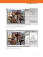
Figure 5.3
When you choose File
➯
New, this will open the New document
dialog shown here (top left). Initially, you can go to the Preset menu and choose
a preset type such as: Photo, Web or Film & Video. Depending on the choice
you make here, this will affect the size options available in the Size menu (top
right). If you use the New document dialog to confi gure a custom setting, you
can click on the Save Preset button to save this as a New Document preset
(right). When you save a New Document preset this will appear listed in the
main Preset menu (see top left).
Creating a new document
If you want to create a new document in Photoshop with
a blank canvas, go to the File menu and choose New .
This will open the dialog shown in Figure 5.3, where you
can select a preset setting type from the Preset pop-up
menu followed by a preset size option from the Size menu.
When you choose a preset setting, the resolution will adjust
automatically depending on whether it is a preset used for
print or computer screen type work (you can change the
default resolution settings for print and screen in the
Units & Rulers Photoshop preferences). Alternatively,
you can manually enter new document dimensions and
resolution in the fi elds below.
The Advanced section lets you do extra things like
choose a specifi c profi led color space and after you have
entered custom settings in the New Document dialog these
can be saved by clicking on the Save Preset button. In the
New Document Preset dialog that’s shown below you will
notice that there are options that will allow you to select
which attributes are to be included in the saved preset.
Martin Evening
Adobe Photoshop CS4 for Photographers
270
Altering the image size
The image size dimensions and resolution can be adjusted
using the Image Size dialog. The Image Size dialog will
normally open with the Resample Image box checked,
which means that as you enter new pixel dimension values,
measurement values or alter the resolution, the overall
image size adjusts accordingly. As you alter one set of
units you’ll see the others adjust simultaneously. When
Resample Image is unchecked, the pixel dimensions will
be grayed out and any adjustment made to the image will
not alter the total pixel dimensions (only the relationship
between the measurement units and the resolution).
Remember the rule I mentioned earlier: the number of
pixels = physical dimension × (ppi) resolution. You can put
that to test here and use the Image Size dialog as a training
tool to better understand the relationship between the
number of pixels, the dimensions and the resolution. The
Constrain Proportions checkbox links the horizontal and
vertical dimensions, so that any adjustment is automatically
scaled to both axis. Only uncheck this box if you wish to
squash or stretch the image when adjusting the image size.
Figure 5.4
To change the image output dimensions but retain the resolution,
leave the Resample box checked. To change the image output dimensions with a
corresponding change in resolution, leave the Resample box unchecked. Click on the
Auto button to open the Auto Resolution dialog. This will help you pick the ideal pixel
resolution for repro work based on the line screen resolution.
Resolution and viewing distance
In theory the larger a picture is printed,
the further away it is meant to be viewed,
and the pixel resolution should not have
to be scaled up in size in order to achieve
the same perception of sharpness. There
are limits though, below which the quality
will never be sharp enough at normal
viewing distance (except at the smallest of
print sizes). It also depends on the image
subject matter – a picture containing a lot
of intricate detail will need more pixels to
do the subject justice and be reproduced
successfully. If you have a picture of a
softly lit, cloudy landscape you can quite
easily get away with enlarging a small
image through interpolation, beyond the
normal constraints.
271
Image editing essentials
Chapter 5
Figure 5.5
This is a close-up view of
the Image Resize dialog, showing the fi ve
interpolation options.
Image interpolation
Image resampling is also known as interpolation and
Photoshop can use one of fi ve methods when calculating
how to resize an image. These interpolation options are
all located in a menu just below the Resample Image
checkbox (see Figure 5.5).
I generally consider ‘ interpolating up’ an image in
Photoshop is preferable to the interpolation methods
found in basic scanner software. Digital fi les captured
from a scanning back or multishot digital camera are
extremely clean and, because there is no grain present, it
is usually possible to magnify a digitally captured image
more successfully than you can a scanned image of
equivalent size. There are other third-party programs that
claim to offer improved interpolation, but there appears
to be little evidence that you will actually gain any major
improvements in image quality over and above what you
can achieve using Photoshop. Here is a guide to how each
of the interpolation methods works and which are the best
ones to use and when.
Nearest Neighbor is the simplest interpolation
method yet I use this quite a lot, such as when I want to
enlarge screen grabs of dialog boxes by 200% for use in
this book. This is because I don’t want the sharp edges of
the dialog boxes to appear fuzzy in print.
Bilinear interpolation calculates new pixels by
reading the horizontal and vertical neighboring pixels. It is
fast, and perhaps that was an important consideration in the
early days of Photoshop, but I don’t see much reason to use
this now.
Bicubic interpolation provides better image quality
when resampling continuous tone images. Photoshop reads
the values of neighboring pixels vertically, horizontally and
diagonally, to calculate a weighted approximation of each
new pixel value. Photoshop intelligently guesses the new
pixel values, by referencing the surrounding pixels.
Martin Evening
Adobe Photoshop CS4 for Photographers
272
Bicubic interpolation methods
The Photoshop bicubic interpolations are improved and
more accurate than before, especially with regard to the
downsampling of images. If you need to apply an extreme
image resampling, either up or down in size, I suggest
that you consider using the Bicubic Sharper or Bicubic
Smoother interpolation methods.
Bicubic Smoother is the ideal choice for making
pictures bigger, as this will result in smoother interpolated
enlargements. It has been suggested that you can also get
good results using Bicubic sharper when interpolating up
and then go directly to print. However, this ignores the fact
that the sharpening should really be applied as a separate
step after interpolating the image, and the sharpening
should be tailored to the fi nal output size (see Chapter 13).
It is therefore better to use Bicubic smoother followed by a
separate print sharpening step. This is because the smooth
interpolation prevents any artifacts in the image from being
enhanced too much and the sharpening can be applied at
the exact right amount for whatever size of print you are
making.
Bicubic Sharper should be used when you want to
reduce an image in size more accurately . If you have a
high resolution digital capture of a detailed subject and
want to make a duplicate copy but at a much lower pixel
resolution, the scaled down image will retain more detail
and sharpness if you use Bicubic Sharper. This will help
avoid the stair-step aliasing that can occur when using other
interpolation methods.
Step interpolation
Some people might be familiar with the step interpolation
technique, where you gradually increase or decrease
the image size by small percentages. This is not really
necessary now because you can use Bicubic Sharper or
Bicubic Smoother to increase or decrease the image size
in a single step. Some people argue that for really extreme
image size changes they still prefer the 10% step method.
Planning ahead
Once an image has been scanned at a
particular resolution and manipulated,
there is no going back. A digital fi le
prepared for advertising usage may never
be used to produce anything bigger than
a 35 MB CMYK separation, but you never
know. It is safer to err on the side of
caution and better to sample down than
have to interpolate up. It also depends
on how much manipulation you intend
doing. Some styles of retouching work
are best done at a magnifi ed size and then
reduced. Suppose you wanted to blend a
small element into a detailed scene. To do
such work convincingly, you need to have
enough pixels to work with to be able to
see what you are doing. For this reason
some professional retouchers will edit a
master fi le that is around 100 MB RGB or
bigger even.
Another advantage of working with
large fi le sizes is that you can always
guarantee being able to meet clients’
constantly changing demands, although
the actual resolution required to illustrate
a glossy magazine double-page full-bleed
spread is probably only around 40–60
MB RGB or 55–80 MB CMYK. Some
advertising posters may even require
smaller fi les than this, because the print
screen on a billboard poster is that much
coarser. When you are trying to calculate
the optimum resolution you cannot rely
on being fully provided with the right
advice from every printer. Sometimes it
will be necessary to anticipate the required
resolution by referring to the table in
Figure 5.6. This shows some sample fi le
size guides for different types of print job.
273
Image editing essentials
Chapter 5
Figure 5.6
The above table shows a comparison of pixel resolution, megapixels, megabyte fi le size and output dimensions at different
resolutions, both in inches and in centimeters.
Figure 5.7
Here is a rough guide to the sort of fi le sizes required to reproduce either a mono or CMYK fi le for printed use. The table
contains fi le size information for output at multiples of x1.5 the screen ruling and x2 the screen ruling.
Inches Centimeters Inches Centimeters
Pixel size Megapixels MB (RGB)
MB (CMYK)
200 ppi 80 ppc 300 ppi 120 ppc
1600 x 1200 2 6 7.5 8 x 6 20 x 15 5.5 x 4 13.5 x 10
2400 x 1800 4.3
12.5 16.5 12 x 9 30 x 22.5 8 x 6 20 x 15
3000 x 2000 6 17.5 23.5 15 x 10 37.5 x 25 10 x 6.5 25 x 17
3500 x 2500 8.75 25 33.5 17.5 x 12.5 44 x 31 11.5 x 8.5 29 x 21
4000 x 2850 11.4 32.5 43.5 20 x 14 50 x 36 13.5 x 9.5 33.5 x 24
4500 x 3200 14.4 41 54.5 22.5 x 16 56 x 40 15 x 10.5 37.5 x 27
5000 x 4000 20 57 76 25 x 20 62.5 x 50 16.5 x 13.5 42 x 33.5
Output use Screen
ruling
x1.5 Output
resolution
MB
Grayscale
MB
CMYK
x2 Output
resolution
MB
Grayscale
MB
CMYK
A3 Newspaper
single pag
e
85 lpi 130 ppi 3 12.5 170 ppi 5.5 21.5
A3 Newspaper
single page
120 lpi 180 ppi 6 24 240 ppi 10.5 42.5
A4 Magazine
mono single page
120 lpi 180 ppi 3 NA 240 ppi 5.3 NA
A4 Magazine
mono double page
120 lpi 180 ppi 6 NA 240 ppi 10.6 NA
A4 Magazine
single page
133 lpi 200 ppi 3.7 14.8 266 ppi 6.5 26.1
A4 Magazine
double page
133 lpi 200 ppi 8 29.6 266 ppi 13 52.2
A4 Magazine
single page
150 lpi 225 ppi 4.7 18.7 300 ppi 8.3 33.2
A4 Magazine
double page
150 lpi 225 ppi 9.4 37.4 300 ppi 17 66.4
Martin Evening
Adobe Photoshop CS4 for Photographers
274
WYSIWYG image editing
If you want true WYSIWYG editing (what
you see is what you get), it is important
that you follow the instructions laid out
in the Chapter 2 on how to calibrate the
display and confi gure the color settings.
Do this and you will now be ready to start
editing your photographs with confi dence.
Basic pixel editing
In Chapter 3 we explored the use of adjustments and
other tools in Camera Raw to optimize a photo before it
is opened in Photoshop as a rendered pixel image. The
following section is all about the main image adjustment
controls in Photoshop and how you can use these to fi ne-
tune your images, or use them as an alternative to Camera
Raw such as when editing camera shot JPEGs or scanned
TIFFs. The techniques discussed here should be regarded
as essential foundation skills for Photoshop image editing
because however you bring your images into Photoshop,
you will at some point need to know how to work with the
basic image editing tools such as Levels and Curves.
If you intend bringing your images in via Camera
Raw, it can be argued that Photoshop image adjustments
are unnecessary since Camera Raw provides you with
everything you need to produce perfectly optimized photos.
Even so, you will still fi nd the information in this chapter is
important, since these are the techniques every Photoshop
user needs to be aware of and use when applying things
like localized corrections. So, for now, let’s look at some
basic pixel image editing principles and techniques.
The image histogram
The histogram is a bar chart that graphically represents
the relative distribution of the various tones (referred to
as Levels) that make up a digital photograph. An 8-bit per
channel grayscale image has a single channel and uses
256 shades of gray to describe all the levels of tone from
black to white. Black has a levels value of 0 (zero), white
has a levels value of 255 and all the numbers in between
represent the shades of gray going from black to white.
The histogram is like a graph with 256 increments, each
representing how often a particular levels number (a
specifi c gray color) occurs in the image. Figure 5.8 shows
a typical histogram such as you’ll see in the Histogram,
Levels and Curves panels. This diagram also shows how
the appearance of the graph relates to the tonal structure of
a photographic image.
Raw to pixel image conversions
Once a raw image has been rendered as
a pixel image you cannot revert to the
raw data version because the raw to pixel
image conversion is a one-way process.
Once you have done this, the only way you
can undo something in the raw processing
is to revert to the original raw image and
generate a new pixel image copy. Although
the goal of this book is to show you how
to work as non-destructively as possible,
this is the one step in the process where
there is no going back and you therefore
need to be sure that the photograph you
start editing in Photoshop is as fully
optimized as possible. In the case of JPEG
images, you can edit these in Camera Raw
if you like, or you can cut out Camera Raw
completely and use the examples shown
in this chapter and use Photoshop to carry
out the image optimization.
275
Image editing essentials
Chapter 5
Figure 5.8
Here is an image histogram that represents the distribution of tones from
the shadows to the highlights. Because this photograph mostly contains dark shades
of gray you will notice that the levels are predominantly located to the left end of the
histogram. The height of each bar in the histogram indicates the frequency of pixels
that occur at each levels point.
Number of pixels
Black White
Figure 5.9
The warning triangle in the
Histogram panel indicates that you need to click
on the Refresh button above to update it.
Now let’s look at what that information can tell us
about a digital image. The histogram graphically shows the
distribution of tones in an image. A low-key photograph
(such as the one shown in Figure 5.8) will show most
of the peaks on the left. Most importantly, it shows the
positioning of the shadow and highlight points. When
you apply a tonal correction using Levels or Curves, the
histogram provides a visual clue that helps you judge
where the brightest highlights and deepest shadows should
be. The histogram also tells you something about the
condition of the image you are editing. If there are peaks
jammed up at either ends of the histogram, this suggests
that the highlights or shadows are most likely clipped and
that when the original photograph was scanned or captured
it was effectively under- or overexposed. Unfortunately, if
The Histogram panel
There has always been a histogram in the
Levels dialog and there is also a Histogram
panel, which when working in Photoshop
gives you even more feedback. With the
Histogram panel, you can continuously
observe the effect your image editing
has on the image levels and you can also
check the histogram while making any
type of image adjustment. The Histogram
panel only provides an approximate
representation of the image levels. So, to
ensure that the Histogram panel is giving
an accurate representation of the image
levels it is advisable to force Photoshop to
update the histogram view, by clicking on
the Refresh button at the top of the panel.
Martin Evening
Adobe Photoshop CS4 for Photographers
276
the levels are clipped at either end of the scale you can’t
restore the detail that has been lost here. If there are gaps
in the histogram, this will most likely indicate a poor
quality scan or that the image had previously been heavily
manipulated.
Throughout this book I will try to guide you to work as
effi ciently and as non-destructively as possible. But even so,
anything we do to adjust the levels to make an image look
better will result in some data loss. This is quite normal and
an inevitable consequence of the image editing process. The
steps on the page opposite illustrate what happens when you
edit a photograph. As you adjust the input levels, moving
the Input sliders further apart, you will stretch the levels
and gaps will start appearing in the histogram. But more
importantly, stretching the levels further apart can result in
less well-defi ned tonal separation and therefore less detail in
these regions of the image. This is particularly a problem at
the shadow end of the scale because there are fewer levels of
usable tone information in the shadows compared with the
highlights (see the section on Digital exposure on page 174).
As you move the Input sliders closer together you will
compress the tones in the image and these can appear
as spikes in the histogram. This too can cause data loss,
sometimes resulting in fl atter tone separation (there is
also an example of this in the section on Camera Raw
Brightness adjustments on page 177).
The histogram can therefore be used to provide visual
feedback on the levels information in an image and to show
whether there is clipping at either end of the scale. But
does it really matter whether we obtain a smooth histogram
or not? If you are preparing a photograph to go to a print
press, you would be lucky to detect more than 50 levels of
tonal separation from any single ink plate. So the loss of a
few levels at the completed edit stage does not necessarily
imply that you have too little digital tonal information
from which to reproduce a full-tonal range image in print.
However, if you begin with a bad-looking histogram, the
image is only going to be in a worse state after it has been
retouched. For this reason it is best to start out with the best
quality scan or capture you can get.
Interpreting an image
A digital image is nothing more than
a lot of numbers and it is how those
numbers are interpreted in Photoshop
that creates the image you see on the
display. We can use our eyes to make
subjective judgements about how the
picture looks, but we can also use the
number information to provide useful and
usable feedback. The Info panel is your
friend. If you understand the numbers, it
can help you see the fi ne detail that your
eyes are not sharp enough to discern. And
we also have the Histogram panel, which
is a godsend to geeks who just love all
that statistical analysis stuff but it is also
an excellent teaching tool. The Histogram
panel makes everything that follows much
easier to understand.
277
Image editing essentials
Chapter 5
1
Here is an image that displays an evenly distributed range of tones in the
accompanying Histogram panel.
2
If I apply a Levels image adjustment and drag the middle (Gamma) Input slider
to the left, this will lighten the image. The Histogram panel on the right shows the
histogram display after the adjustment has been applied. To understand what has
happened here, this histogram represents the newly mapped levels. The levels
that were in the section of the histogram to the left of the Gamma slider have been
stretched and the levels that were to the right of the Gamma slider have now been
compressed.
Basic Levels editing and the histogram
This example was carried out on an 8-bit RGB image, so it
should come as no surprise that the histogram broke down
as soon as I applied a simple Levels adjustment (in the
following section we are going to look at the advantages of
editing in 16-bits per channel mode).
Martin Evening
Adobe Photoshop CS4 for Photographers
278
Bit depth
Bit depth refers to the maximum number of levels per
channel that can be contained in a photograph. For
example, a 24-bit RGB color image is made up of three
8-bit image channels, where each 8-bit channel can contain
up to 256 levels of tone, while a 16-bit per channel image
can have up to 32,768 data points per color channel
(because in truth, Photoshop’s 16-bit depth is 15 bits +1).
So although Photoshop’s 16-bits per channel mode is
actually 15-bits, this shouldn’t really matter since 15-
bits is plenty enough levels to contain the levels data that
can be captured by any camera or scanner device. JPEG
images are always limited to 8-bits, but TIFF and PSD fi les
can be in 8-bits or 16-bits per channel. Photoshop only
offers 8-bits or 16-bits per channel modes for standard
integer channel images (32-bit support uses fl oating point
Understanding bit depth
To understand what the bit depth numbers
mean it is best to begin with a grayscale
image where there is just luminosity. A
1-bit or bitmapped image contains black or
white pixels only. A 2-bit image contains
4 levels (2
2
), 3-bit 8 levels (2
3
) and so on,
up to 8-bit (2
8
) with 256 levels of gray.
Therefore, a 24-bit RGB color image is
made up of 3 x 8-bit channels where each
grayscale channel represents a red, green
or blue color and, because the channels
overlap, each pixel is capable of defi ning
up to 16.7 million possible colors (2
8
x 3).
Figure 5.10
The bit depth of an image is a mathematical description of the
maximum levels of tone that are possible, expressed as a power of 2. A bitmap image
contains 2 to the power of 1 (2 levels of tone), in other words, either black or white
tone only. A normal Photoshop 8-bit grayscale image or individual color channel in
a composite color image will contain 2 to the power of 8 (up to 256 levels of tonal
information). When three RGB 8-bit color channels are combined together to form a
composite color image, the result is a 24-bit color image that can contain up to 16.7
million shades of color.
Combined RGB image (24 bit)
Green channel (8 bit)
Red channel (8 bit)
Blue channel (8 bit)
279
Image editing essentials
Chapter 5
channels). Therefore, any source image with more than
8-bits per channel has to be in the 16-bits per channel
mode. Most scanners are capable of capturing 12-bits per
channel data, which means that scanned images have to be
saved using 16-bits per channel in order to preserve all of
the 12-bits per channel data. Once the image is opened in
Photoshop you’ll then have access to all the levels data that
was captured in the original scanned image.
In the case of raw fi les, a raw image contains all the
original levels data, which is usually captured at a bit
depth of 12-bits or even 14-bits per channel. Camera Raw
image adjustments are calculated using 16-bits per channel
so, once again, all the levels information that was in the
original can be preserved when you save a Camera Raw
processed raw image using 16-bits per channel.
8-bit versus 16-bit image editing
There are those who have argued that 16-bit editing is
a futile exercise because no one can tell the difference
between an image that has been edited in 16-bit and one
that has been edited in 8-bit. Personally I believe this to
be a foolish argument. If a scanner or camera is capable of
capturing more than 8-bits per channel, why not make full
use of the extra tonal information? In the case of fi lm scans,
you might as well save the freshly scanned images using the
16-bits per channel mode and apply the initial Photoshop
edits using Levels or Curves in 16-bits. If you preserve
all the levels in the original through these early stages of
the edit process, you’ll have more headroom to work with
and avoid dropping useful image data. It may only take a
second or two longer to edit an image in 16-bits per channel
compared with when it is in 8-bit, but even if you only carry
out the initial edits in 16-bit and then convert to 8-bit you’ll
retain signifi cantly more image detail.
The second point is you never know what the future
has in store. On pages 310–313 we shall be looking at
Shadows/Highlights adjustments. This feature can be used
to emphasize detail that might otherwise remain hidden in
the shadows or highlights. This feature exploits the fact that
a deep-bit image can contain lots of hidden levels data that
Why is 16-bits really 15-bits?
If you have a keen knowledge of math,
you will notice that Photoshop’s 16-bits
per channel mode is actually 15-bit as it
uses only 32,768 levels out of a possible
65,536 levels when describing a 16-bit
mode image. This is because having a
tonal range that goes from 0 to 32,767 is
more than adequate to describe the data
coming off any digital device. And also
because from an engineering point of view,
15-bit math calculations give you an exact
midpoint value, which can be important for
precise blending.
Bit depth precision
A higher bit depth doesn’t add more
pixels to an image. Instead, it offers a
greater level of precision to the way tone
information is recorded by the camera or
scanner sensor. One way to think about
bit-depth is to consider the difference
between having the ability to measure
something with a ruler that is accurate to
the nearest inch, compared with one that
can measure to the nearest millimeter.
Martin Evening
Adobe Photoshop CS4 for Photographers
280
2
With each version I applied two sequential Levels adjustments. The fi rst (shown
here on the left) compressed the output levels to an output range of 120–136. I then
applied a second Levels adjustment in which I expanded these levels to 0–255 again.
3
The outcome of this can be clearly seen when examining the individual color
channels. On the left you can see the image histogram for the 8-bit fi le green channel
and on the right you can see a much smoother histogram with the original 16-bit fi le.
1
Here, I started out with a full color image that was in 16-bits per channel mode and
created a duplicate that was converted to 8-bits per channel mode.
Bit depth status
You can check the bit depth of an image
quite easily by looking at the document
window title bar, where it will indicate the
bit-depth as being 8, 16 or 32-bit.
2
Wi
th
e
ac
h
ve
rs
io
n
I
ap
pl
ie
d
tw
o
se
qu
en
ti
a
Levels adjustments The first (shown
Comparing 8-bit with 16-bit editing
281
Image editing essentials
Chapter 5
can be manipulated to reveal more detail in the shadows or
highlight areas. The Shadows/Highlights adjustment works
fi ne with 8-bit images of course, but you’ll get better results
if you scan or capture in 16-bit per channel mode fi rst.
Photoshop also offers extensive support for 16-bit mode
editing. You can crop, rotate, make all the usual image
adjustments, use all the Photoshop tools and work with
layers in 16-bit mode, in grayscale, RGB, CMYK and Lab
color modes, but only a few fi lters are available such as the
Lens Correction and Liquify fi lter. You may not feel the
need to use 16-bits per channel all the time for every job,
but I would say that for critical jobs where you don’t want
to lose an ounce of detail, it is essential to make at least all
your preliminary edits in 16-bits.
In the tutorial shown opposite, I started with an image
that was in 16-bits mode and created a duplicate that was
converted to 8-bits. I then proceeded to compress the
levels and expand them again in order to demonstrate how
keeping an image in 16-bits per channel mode provides a
more robust image mode for major tone and color edits.
Admittedly this is an extreme example, but preserving an
image in 16-bits offers a signifi cant extra margin of safety
when making everyday image adjustments.
16-bit and color space selection
For a long time now Photoshop experts such as myself have
advocated editing in RGB using a conservative gamut color
space such as Adobe RGB (if you want to fi nd out more
about RGB color spaces then you will need to read Chapter
12 on color management). Although 16-bit editing is not
new to Photoshop, it is only since the advent of Photoshop
CS that it has been possible to edit more extensively in
16-bit. One of the advantages this brings is that we are no
longer limited to editing in a relatively small gamut RGB
workspace. It is perfectly safe to use a large gamut space
such as ProPhoto RGB when you are editing in 16-bits
per channel mode because you’ll have so many more data
points in each color channel to work with compared to when
you edit in a standard RGB space such as ColorMatch or
Adobe RGB (see the following section on RGB edit spaces).
Camera Raw and bit depth output
Bearing in mind what I have said about
the importance of carrying out all the
major tone edits in 16-bit, Camera Raw
does just that. If you use Camera Raw to
process a raw camera fi le or a 16-bit TIFF,
the initial image edits will all be done
in 16-bits. If you are satisfi ed that the
result of the Camera Raw processing is a
perfectly optimized image, it can be argued
there is less harm in converting such a
fi le to an 8-bits per channel mode image
in Photoshop. But as I mentioned in the
main text, you never know when you might
be required to adjust an image further.
Keeping a photo in 16-bits can give
you peace of mind, knowing that you’ve
preserved as many levels as possible from
the original.
Martin Evening
Adobe Photoshop CS4 for Photographers
282
The RGB edit space and color gamut
No Photoshop book for photographers would be complete
without a discussion about which RGB working space to
choose from the RGB Working Spaces menu in the Edit
➯
Color Settings dialog (Figure 5.11).
For photo editing work, the choice really boils down to
Adobe RGB or ProPhoto RGB. The best way to illustrate
the differences between these two RGB color spaces is to
consider how colors captured by the camera or scanner are
best preserved when they are converted to print. Figure
5.12 shows (on the left) top and side views of a 3D plot
for the color gamut of a digital camera, seen relative to
a wire frame of the Adobe RGB working space. Next to
this you can see top and side views of a glossy inkjet print
space relative to Adobe RGB. You will notice here that
Adobe RGB does clip both the input and output color
Figure 5.12
This diagram shows on the left, a top and side view of the gamut of
a digital camera source space plotted as a solid shape within a wire frame shape
representing the color gamut of the Adobe RGB edit space. On the right is a top and
side view of the gamut of a glossy inkjet printer color space plotted as a solid shape
within a wire frame of the same Adobe RGB space.
Figure 5.11
The Color Settings dialog.
Top view Top view
Side view Side view