kelly l murdock 3ds Max 2009 Bible phần 4 pdf
Bạn đang xem bản rút gọn của tài liệu. Xem và tải ngay bản đầy đủ của tài liệu tại đây (7.75 MB, 130 trang )
You use the Smoothing Groups option to assign a subobject to a unique smoothing group. To do this, select
a subobject and click a Smoothing Groups number. The Select By SG button, like the Select By ID button,
opens a dialog box where you can enter a Smoothing Groups number, and all subobjects with that number
are selected. The Clear All button clears all Smoothing Groups number assignments, and the Auto Smooth
button automatically assigns Smoothing Groups numbers based on the angle between faces as set by the
value to the right of the Auto Smooth button.
The Polygon Properties rollout also includes options for setting vertex Color, Illumination, and Alpha values.
Subdivision Surface
Editable Poly objects include an extra rollout called Subdivision Surface that automatically smoothes the
object when enabled. The Subdivision Surface rollout, shown in Figure 13.27, applies a smoothing algo-
rithm known as NURMS, which stands for Non-Uniform Rational Mesh Smooth. It produces similar results
to the MSmooth button but offers control over how aggressively the smoothing is applied; the settings can
be different for the viewports and the renderer.
FIGURE 13.27
The Subdivision Surface rollout includes controls for NURMS subdivision.
To enable NURMS subdivision, you need to enable the Use NURMS Subdivision option. The Smooth Result
option places all polygons into the same smoothing group and applies the MeshSmooth to the entire object.
Applying NURMS with a high Iterations value results in a very dense mesh, but the Isoline Display option
displays a simplified number of edges, making the object easier to work with. The process of smoothing adds
many edges to the object, and the Isoline Display option displays only the isolines. The Show Cage option
makes the surrounding cage visible or invisible. The two color swatches to the right of the Show Cage option
let you set the color of the cage and the selection.
The Iterations value determines how aggressive the smoothing is. The higher the Iterations value, the more
time it takes to compute and the more complex the resulting object. The Smoothness value determines how
sharp a corner must be before adding extra faces to smooth it. A value of 0 does not smooth any corners,
and a maximum value of 1.0 smoothes all polygons.
Cage color
Cage Selection color
370
Modeling Basics
Part III
19_381304-ch13.qxp 7/7/08 3:03 PM Page 370
Each smoothing iteration quadruples the number of faces. If you raise the number of Iterations
too high, the system can become unstable quickly.
The two check boxes in the Render section can be used to set the values differently for the Display and
Render sections. If disabled, then both the viewports and the renderer use the same settings. The smoothing
algorithm can be set to ignore smoothing across Smoothing Groups and Materials.
If the Show Cage option is enabled (at the bottom of the Edit Geometry rollout), an orange cage surrounds
the NURMS object and shows the position of the polygon faces that exist if NURMS is disabled. This cage
makes selecting the polygon faces easier.
Tutorial: Modeling a tooth
If you’ve ever had a root canal, then you know how much pain dental work can cause. Luckily, modeling a
tooth isn’t painful at all, as you’ll see in this example.
To model a tooth using NURMS, follow these steps:
1. Select Create ➪ Standard Primitives ➪ Box, and drag in the Top viewport to create a Box object.
Set its dimensions to 140 × 180 × 110 with Segments of 1 × 1 × 1. Then right-click, and select
Convert To ➪ Editable Poly from the pop-up quadmenu.
2. Click the Polygon icon in the Selection rollout to enable Polygon subobject mode. Then select the
Top viewport, and press B to change it to the Bottom viewport. Then click the box’s bottom poly-
gon in the Bottom viewport.
3. Click the Select and Scale button (R), and scale the bottom polygon 10%.
4. Drag over the entire object to select all polygons, and click the Tessellate button in the Edit
Geometry rollout once to divide the polygon into more polygons. Then select Edit ➪ Region ➪
Window (or click the Window/Crossing button in the main toolbar) to enable the Window selec-
tion method, and drag over the bottom of the Box object in the Left viewport to select just the
bottom polygons. Click the Tessellate button again.
5. Select the Vertex subobject mode in the Selection rollout, press and hold the Ctrl key, and select
the vertices at the center of each quadrant. Then move these vertices downward in the Left view-
port a distance about equal to the height of the Box.
6. Select the Bottom viewport again, and press T to change it back to the Top viewport. Select the
single vertex in the center of the polygon with the Ignore Backfacing option enabled in the
Selection rollout, and drag it slightly downward in the Left viewport.
7. Disable the Ignore Backfacing option in the Selection rollout, and select the entire second row of
vertices in the Left viewport. With the Select and Scale tool, scale these vertices toward the center
in the polygon in the Top viewport.
8. In the Subdivision Surface rollout, enable the Use NURMS Subdivision option and set the
Iterations value to 2.
Figure 13.28 shows the completed tooth.
CAUTION
CAUTION
371
Modeling with Polygons
13
19_381304-ch13.qxp 7/7/08 3:03 PM Page 371
FIGURE 13.28
The organic look for this tooth is accomplished with NURMS.
Summary
Meshes are probably the most common 3D modeling types. You can create them by converting objects to
Editable Meshes or Editable Poly objects or by collapsing the Stack. Editable Poly objects in Max have a
host of features for editing meshes, as you learned in this chapter. More specifically, this chapter covered the
following topics:
Creating Editable Poly objects by converting other objects or applying the Edit Poly modifier
The features for editing Editable Poly objects
How to select and use the various mesh subobject modes
Editing mesh objects using the various features found in the Edit Geometry rollout
Changing surface properties using features like NURMS
This chapter concludes Part III, “Modeling Basics.” You’re now ready to learn about dressing up objects with
materials, cameras, and lights. The next chapter covers the basics of applying materials.
372
Modeling Basics
Part III
19_381304-ch13.qxp 7/7/08 3:03 PM Page 372
Materials, Cameras,
and Lighting Basics
IN THIS PART
Chapter 14
Exploring the Material Editor
Chapter 15
Creating and Applying Standard
Materials
Chapter 16
Creating Compound Materials and
Using Material Modifiers
Chapter 17
Adding Material Details with Maps
Chapter 18
Configuring and Aiming Cameras
Chapter 19
Using Lights and Basic Lighting
Techniques
20_381304-pp04.qxp 7/7/08 2:54 PM Page 373
20_381304-pp04.qxp 7/7/08 2:55 PM Page 374
M
aterials are used to dress, color, and paint objects. Just as materials in
real life can be described as scaly, soft, smooth, opaque, or blue, materi-
als applied to 3D objects can mimic properties such as color, texture,
transparency, shininess, and so on. In this chapter, you learn the basics of work-
ing with materials and all the features of the Material Editor.
Understanding Material Properties
Before jumping into the Material Editor, let’s take a close look at the type of mate-
rial properties that you will deal with. Understanding these properties will help
you as you begin to create new materials.
Up until now, the only material property that has been applied to an object has
been the default object color, randomly assigned by Max. The Material Editor can
add a whole new level of realism using materials that simulate many different
types of physical properties.
Many of these material properties are not visible until the scene is
rendered.
Colors
Color is probably the simplest material property and the easiest to identify.
However, unlike the object color defined in the Create and Modify panels, there
isn’t a single color swatch that controls an object’s color.
Consider a basket of shiny red apples. When you shine a bright blue spotlight on
them, all the apples turn purple because the blue highlights from the light mix
with the red of the apple’s surface. So, even if the apples are assigned a red mate-
rial, the final color in the image might be very different because the light makes
the color change.
NOTE
NOTE
375
IN THIS CHAPTER
Understanding Material
properties
Working with the Material Editor
Using the Material/Map Browser
Working with libraries of
materials
Using the Material/Map
Navigator
Exploring the Material Editor
21_381304-ch14.qxp 7/7/08 2:38 PM Page 375
Within the Material Editor are several different color swatches that control different aspects of the object’s
color. The following list describes the types of color swatches that are available for various materials:
Ambient: Defines an overall background lighting that affects all objects in the scene, including
the color of the object when it is in the shadows. This color is locked to the Diffuse color by
default so that they are changed together.
Diffuse: The surface color of the object in normal, full, white light. The normal color of an object
is typically defined by its Diffuse color.
Specular: The color of the highlights where the light is focused on the surface of a shiny material.
Self-Illumination: The color that the object glows from within. This color takes over any shad-
ows on the object.
Filter: The transmitted color caused by light shining through a transparent object.
Reflect: The color reflected by a raytrace material to other objects in the scene.
Luminosity: Causes an object to glow with the defined color. It is similar to Self-Illumination
color but can be independent of the Diffuse color.
Standard materials don’t have Reflectivity and Luminosity color swatches, but these swatches
are part of the Raytrace material.
If you ask someone the color of an object, he or she would respond by identifying the Diffuse color, but all
these properties play an important part in bringing a sense of realism to the material. Try applying very dif-
ferent, bright materials to each of these color swatches and notice the results. This gives a sense of the con-
tribution of each color.
For realistic materials, your choice of colors depends greatly on the scene lights. Indoor lights
have a result different from an outdoor light like the sun. You can simulate objects in direct
sunlight by giving their Specular color a yellow tint and their Ambient color a complementary, dark, almost
black or purple color. For indoor objects, make the Specular color bright white and use an Ambient color
that is the same as the Diffuse color, only much darker. Another option is to change the light colors instead
of changing the specular colors.
Opacity and transparency
Opaque objects are objects that you cannot see through, such as rocks and trees. Transparent objects, on the
other hand, are objects that you can see through, such as glass and clear plastic. Max’s materials include sev-
eral controls for adjusting these properties, including Opacity and several Transparency controls.
Opacity is the amount that an object refuses to allow light to pass through it. It is the opposite of trans-
parency and is typically measured as a percentage. An object with 0 percent opacity is completely transpar-
ent, and an object with 100 percent opacity doesn’t let any light through.
Transparency is the amount of light that is allowed to pass through an object. Because this is the opposite of
opacity, transparency can be defined by the opacity value. Several options enable you to control trans-
parency, including Falloff, Amount, and Type. These options are discussed later in this chapter.
Reflection and refraction
A reflection is what you see when you look in the mirror. Shiny objects reflect their surroundings. By defin-
ing a material’s reflection values, you can control how much it reflects its surroundings. A mirror, for exam-
ple, reflects everything, but a rock won’t reflect at all.
TIP
TIP
NOTE
NOTE
376
Materials, Cameras, and Lighting Basics
Part IV
21_381304-ch14.qxp 7/7/08 2:38 PM Page 376
Reflection Dimming controls how much of the original reflection is lost as the surroundings are reflected
within the scene.
Refraction is the bending of light as it moves through a transparent material. The amount of refraction that a
material produces is expressed as a value called the Index of Refraction. The Index of Refraction is the
amount that light bends as it goes through a transparent object. For example, a diamond bends light more
than a glass of water, so it has a higher Index of Refraction value. The default Index of Refraction value is
1.0 for objects that don’t bend light at all. Water has a value of 1.3, glass a value of around 1.5, and solid
crystal a value of around 2.0.
Shininess and specular highlights
Shiny objects, such as polished metal or clean windows, include highlights where the lights reflect off their
surfaces. These highlights are called specular highlights and are determined by the Specular settings. These
settings include Specular Level, Glossiness, and Soften values.
The Specular Level is a setting for the intensity of the highlight. The Glossiness determines the size of the
highlight: Higher Glossiness values result in a smaller highlight. The Soften value thins the highlight by
lowering its intensity and increasing its size.
A rough material has the opposite properties of a shiny material and almost no highlights. The Roughness
property sets how quickly the Diffuse color blends with the Ambient color. Cloth and fabric materials have
a high Roughness value; plastic and metal Roughness values are low.
Specularity is one of the most important properties that we sense to determine what kind of
material the object is made from. For example, metallic objects have a specular color that is
the same as their diffuse color. If the colors are different, then the objects look like plastic instead of metal.
Other properties
Max uses several miscellaneous properties to help define standard materials, including Diffuse Level and
Metalness.
The Diffuse Level property controls the brightness of the Diffuse color. Decreasing this value darkens the
material without affecting the specular highlights. The Metalness property controls the metallic look of the
material. Some properties are available only for certain material types.
Before proceeding, you need to understand the difference between a material and a map. A
material
is an effect that permeates the 3D object, but most
maps
are 2D images (although
procedural 3D maps also exist) that can be wrapped on top of the object. Materials can contain maps, and
maps can be made up of several materials. In the Material Editor, materials appear shaded in the sample
slots, and maps appear as 2D images. Usually, you can tell whether you’re working with a material or a map
by looking at the default name. Maps show up in the name drop-down list as Map and a number (Map #1),
and materials are named a number and Default (7- Default).
Working with the Material Editor
The Material Editor is the interface with which you define, create, and apply materials. You can access the
Material Editor by choosing Rendering ➪ Material Editor, clicking the Material Editor button on the main
toolbar (it has four small rendered spheres on the icon), or using the M keyboard shortcut.
NOTE
NOTE
NOTE
NOTE
377
Exploring the Material Editor
14
21_381304-ch14.qxp 7/7/08 2:38 PM Page 377
Using the Material Editor controls
At the top of the default Material Editor window is a menu of options including Material, Navigation,
Options, and Utilities. The menu commands found in these menus offer the same functionality as the tool-
bar buttons, but the menus are often easier to find than the buttons with which you are unfamiliar.
Below the menus are six sample slots that display a preview of some available materials. Surrounding these
slots are button icons for controlling the appearance of these sample slots and interacting with materials.
Figure 14.1 shows the Material Editor.
The button icons to the right and below the sample slots control how the materials appear in the editor.
These buttons are defined in Tables 14.1 and 14.2.
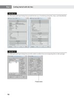
FIGURE 14.1
Use the Material Editor window to create, store, and work with materials.
Sample slots
Material names
Horizontal buttons
Vertical buttons
378
Materials, Cameras, and Lighting Basics
Part IV
21_381304-ch14.qxp 7/7/08 2:38 PM Page 378
TABLE 14.1
Material Editor Buttons — Vertical
Toolbar Button Name Description
Sample Type Controls the type of object displayed in the sample slot. The default
(Sphere, object is a sphere. Other options available as flyouts include a cylinder
and a cube. You can also select a custom object to use as the preview
Cylinder, object.
Box,
Custom)
Backlight (L) Turns backlighting in the selected sample slot on or off.
Background (B) Displays a checkered background image (or a custom background)
behind the material, which is helpful when displaying a transparent
material.
Sample UV Tiling Sets UV tiling for the map in the sample slot. The default is 1 × 1.
(1×1, Additional options available as flyouts are 2 × 2, 3 × 3, and 4 × 4. This
setting affects only maps.
2 × 2,
3 × 3,
4 × 4)
Video Color Check Checks the current material for colors that are unsupported by the NTSC
and PAL formats.
Make Preview (P), Used to generate, view, and save material preview renderings. These
animated material previews enable you to see the effect of an animated
Play Preview, material before rendering.
Save Preview
Options (O) Opens the Material Editor Options dialog box. This dialog box includes
settings for enabling material animation, loading a custom background,
defining the light intensity and color, and specifying the number of
sample slots.
Select by Material Selects all objects using the current material. This button opens the
Select Objects dialog box with those objects selected.
Material/ Opens the Material/Map Navigator dialog box. This dialog box displays
Map Navigator a tree of all the levels for the current material.
379
Exploring the Material Editor
14
21_381304-ch14.qxp 7/7/08 2:38 PM Page 379
TABLE 14.2
Material Editor Buttons — Horizontal
Toolbar Button Name Description
Get Material (G) Opens the Material/Map Browser for selecting materials.
Put Material in Scene Updates the materials applied to objects in the viewport
after materials have been edited.
Assign Material Applies the selected object with the selected material.
to Selection
Reset Map/Mtl to Removes any modified properties and resets the material
Default Settings properties to their defaults.
Make Material Copy Creates a copy of the current material in the selected sample
slot.
Make Unique Makes instanced materials into a new stand-alone material.
Put to Library Opens a simple dialog box that lets you rename the material
and saves it into the current open library.
Material Effects Channel Sets a unique channel ID for applying post-processing
effects. This button includes channels 1–15 as flyouts. A
material with channel 0 means that no effect will be
applied.
Show Map in Viewport, Displays 2D material maps and hardware maps on objects
in the viewports.
Show Hardware Map
in Viewport
Show End Result Displays the material in the sample slot with all levels
applied. If this button is disabled, you will see only the level
that is currently selected.
Go to Parent Moves up one level for the current material. This applies
only to compound objects with several levels.
Go Forward to Sibling Selects the next map or material at the same level.
Pick Material From Enables you to select a material from an object in the scene
Object and load the material into the selected sample slot.
Material drop-down list Lists the elements in the current material. You can change
the material or map name by typing a new name in this
field.
Type button Displays the current material or map type that is being used.
Clicking this button opens the Material/Map Browser where
you can select a new material or map type.
380
Materials, Cameras, and Lighting Basics
Part IV
21_381304-ch14.qxp 7/7/08 2:38 PM Page 380
Below the material name and type button is where the rollouts for the current material are opened. These
rollouts change depending on the material type.
The Material Effects Channel IDs are used with the Rendering Effects dialog box to apply spe-
cific effects, such as glow and blur, to a material. To learn more about these effects, see
Chapter 45, “Using Atmospheric and Render Effects.”
Using the sample slots
The Material Editor includes 24 sample slots that display materials and map examples. Each of these sample
slots contains one material or map. Only one sample slot can be selected at a time: The selected slot is out-
lined with a white border. Click one of the material slots to select it.
Sample slots cannot be empty: They always contain some kind of material.
Sample slots are temporary placeholders for materials and maps. An actual scene can have hundreds of
materials. By loading a material into a sample slot, you can change its parameters, apply it to other objects,
or save it to a library for use in other scenes. When a file is saved, all materials in the Material Editor are
saved with the file.
Twenty-four slots are available, but the default layout displays only six. You can access the other 18 slots
using the scroll bars. You can also change the number of displayed slots. To change the number of slots,
choose Options ➪ Cycle Sample Slots (or press the X key), or right-click any of the material slots and select
2 × 3, 3 × 5, or 4 × 6 from the pop-up menu. These options are also available in the Options dialog box
(keyboard shortcut, O). Figure 14.2 shows the Material Editor with 24 sample slots displayed.
FIGURE 14.2
You can set the number of sample slots in the Material Editor to display 6, 15, or 24 slots.
NOTE
NOTE
CROSS-REF
CROSS-REF
381
Exploring the Material Editor
14
21_381304-ch14.qxp 7/7/08 2:38 PM Page 381
The 24 default sample slots that are by default a dull gray are loaded from the medit.mat file in
the \matlibs subdirectory. To load your own custom default materials, save them into this file.
Magnifying a sample slot
The Material ➪ Launch Magnify Window menu command (also found in the right-click pop-up menu)
opens the material in a magnified window. You can also open this window by double-clicking the sample
slot. You can resize the window to view the material at any size, and you can set it to automatically update
when changes are made. If the Auto option is disabled, you can update the material by clicking the Update
button. Figure 14.3 shows the magnified window. This window is great for seeing the intricate details of a
material.
FIGURE 14.3
Open materials in a magnified window by double-clicking them.
Using different sample objects
You can change the Sample Type object displayed in the sample slots to be a sphere, cylinder, or box using
the Sample Type button at the top right of the Material Editor window.
The Options button (the seventh button from the top in the vertical column of buttons at the right) opens
the Material Editor Options dialog box (also opened with the keyboard shortcut, O), where you can desig-
nate a custom sample object. The sample object must be contained in a .max file. To create a sample object,
create and save a Max scene with a single object that fits inside a 100-unit cube.
The scene can also include custom lights and cameras. The object must have Mapping Coordinates enabled.
You can enable them by selecting the Generate Mapping Coordinates option for primitive objects or by
applying the UVW Map modifier. To make the object available, click the File Name button and select the
option to Load Camera and/or Lights in the Material Editor Options dialog box. After the object loads, its
name appears on the button in the Options dialog box. You can then select the custom object from the
Object Type flyout button. Figure 14.4 shows the Material Editor with several different object types loaded,
including a custom object.
Dragging materials
When you right-click the active sample slot, a pop-up menu appears. From this menu, you can select sev-
eral commands. The Drag/Copy command is a toggle setting. This option also lets you drag and drop mate-
rials between the various sample slots. When the Drag/Copy option is enabled, it leaves a copy of the
material when it’s dragged to another slot. This option also allows you to drag a material to an object in the
viewports. Dropping a material onto an object automatically assigns the material to that object.
NOTE
NOTE
382
Materials, Cameras, and Lighting Basics
Part IV
21_381304-ch14.qxp 7/7/08 2:38 PM Page 382
FIGURE 14.4
You can load a custom sample object to be displayed in the sample slots.
The Drag/Rotate pop-up menu command (also found in the Options menu) lets you rotate the material object
in the sample slot when you drag with the mouse. Dragging on the object rotates it about its X-axis and Y-axis,
and dragging from the corner of the sample slot rotates it about its Z-axis. This feature is useful for looking at
how maps are applied. Holding down the Shift key constrains the rotation about a single axis. The Material ➪
Reset Sample Slot Rotation menu command resets the material object to its original orientation.
You can also drag materials from the sample slots back and forth among the Material/Map Browser, the
Asset Browser Utility, and any rollouts where you can specify maps, such as the Environment Map button
(found in the Environment dialog box, accessed via Rendering ➪ Environment) and the Projector and
Shadow Map buttons (found in the rollouts for a selected light).
Naming materials
Every material has a name that appears beneath the sample slots in a drop-down list. This same name
appears in the Material Editor’s title bar. You can rename a material by typing a new name in the material
name drop-down list. This name appears in the Material/Map Navigator dialog box and in the Track View.
As you create materials, give each one a unique name that is easy to identify. When a material is saved to a
Library with the Put to Library button, a dialog box opens that enables you to rename the material. You can
see the name of any of the materials in the sample slots by moving the mouse over the top of the sample
slot; the material name appears as a tooltip.
If you drag a material from one sample slot to another, a copy is made with the same name as
the original. If one of these materials is changed and then applied to the scene, a warning dia-
log box appears, stating that a material with the same name already exists in the scene. It also gives you the
option of replacing or renaming the material.
NOTE
NOTE
383
Exploring the Material Editor
14
21_381304-ch14.qxp 7/7/08 2:38 PM Page 383
Getting new materials
You load new materials into the sample slots by clicking the Get Material button (the leftmost button on the
horizontal toolbar), choosing the Material ➪ Get Material menu command, or pressing the G key. This
opens the Material/Map Browser where you can select a new material by double-clicking it. The new mate-
rial loads into the selected sample slot. The Material/Map Browser is covered later in this chapter.
The Material/Map Browser holds materials and maps. If you select a material map, a 2D map
is loaded into the sample slot. 2D maps cannot be applied directly to an object in the view-
port. You can tell the difference between maps and materials because maps are flat 2D bitmaps and materi-
als are shown on an object like a sphere.
Assigning materials to objects
When you select a material, you can apply it to the selected object in the viewports with the Assign Material
to Selection button (the third button from the left on the horizontal toolbar under the sample slots) or with
the Material ➪ Assign to Selection menu command. Alternatively, you can drag a material from its sample
slot and drop it on an object.
When you assign a material to an object in the scene, the material becomes “Hot.” A Hot material is auto-
matically updated in the scene when the material parameters change. Hot materials have white corner
brackets displayed around their sample slots. You can “cool” a material by clicking the Copy Material button
(the fifth from the left) or choosing Material ➪ Make Material Copy menu command. This detaches the sam-
ple slot from the material in the scene to which it is applied, so that any changes to the material aren’t
applied to the object.
Whenever a material is applied to an object in the scene, the material is added to a special library of materi-
als that get saved with the scene. Materials do not need to be loaded in one of the sample slots to be in the
scene library. You can also load materials into the scene library that aren’t applied to an object using the Put
Material to Scene button (the second button from the left) or the Material ➪ Put to Scene menu command.
You can see all the materials included in the scene library in the Material/Map Browser by selecting the
Scene radio button.
In addition to the scene library, you can also put materials into a separate material library. The Put to
Library button (the seventh from the left) or the Material ➪ Put to Library menu command places the cur-
rent selected material into the default library. Clicking the Get Material button opens the Material/Map
Browser, where you can see the current library by clicking the Material Library radio button.
Picking materials from a scene
Another useful option is obtaining a material from an object in the scene. Clicking the eyedropper button to
the left of the Material Name or choosing the Material ➪ Pick from Object menu command changes the cur-
sor to an eyedropper. You can then click an object in one of the viewports, and the object’s material is
loaded into the current sample slot.
Selecting objects by material
If you want to select all the objects in your scene with a specific material applied (like the shiny gold mate-
rial), then select the material in the sample slots and click on the Select by Material button in the vertical set
of buttons, or choose the Utilities ➪ Select Objects by Material menu command. This command opens the
Select Objects dialog box with all the objects that have the selected material applied. Clicking the Select
button selects these objects in the viewport.
CAUTION
CAUTION
384
Materials, Cameras, and Lighting Basics
Part IV
21_381304-ch14.qxp 7/7/08 2:38 PM Page 384
Previewing materials and rendering maps
The Material ➪ Make Preview menu command, along with the Make Preview button and the P keyboard
shortcut, opens the Create Material Preview dialog box, shown in Figure 14.5. Using this dialog box, you
can create a preview of an animated material. The dialog box lets you specify the Preview Range and Frame
Rate, as well as the Image Size, which is a percentage of the default resolution.
Animated materials are covered in Chapter 20, “Understanding Animation and Keyframe
Basics.”
After you create a material preview, you can view the preview with the Material ➪ View Preview menu com-
mand. This opens the default media player and plays the animated preview. To save the preview as a file,
use the Material ➪ Save Preview menu command. Preview files are saved as .avi files.
The Utilities ➪ Render Map menu command (also found in the right-click pop-up menu) opens the Render
Map dialog box, shown in Figure 14.5. This option is available only if the selected material has a map
applied. The Render Map dialog box lets you select the Range of frames to include and the Dimensions of
the rendered image. You can click the Files button to open a file dialog box where you can name the render
map and specify the file type. The Render button renders the current map as a bitmap or an animation to
the Rendered Frame Window and to the file (if selected).
FIGURE 14.5
The Create Material Preview and Render Map dialog boxes offer two ways to render a material.
You can save render maps as .AVI, .BMP, .CIN, .EPS, .FLC, .HDR, .JPEG, .PNG, .MOV, .SGI,
.RGB, .RLA, .RPF, .TGA, .jpg, and .DDS files.
Setting Material Editor options
You open the Material Editor Options dialog box by clicking the Options button to the right of the sample
slots, selecting Options from the Options menu, right-clicking the pop-up menu, or by just pressing the O
key. Figure 14.6 shows this dialog box.
NOTE
NOTE
CROSS-REF
CROSS-REF
385
Exploring the Material Editor
14
21_381304-ch14.qxp 7/7/08 2:38 PM Page 385
FIGURE 14.6
The Material Editor Options dialog box offers many options for controlling the Material Editor window.
The Material Editor Options dialog box includes options that control how the materials are displayed in the
sample slots. These options are as follows:
Manual Update: Doesn’t update any changes in the sample slot until the slot is clicked on.
Don’t Animate: Causes materials not to animate when an animation is played or the Time Slider
is dragged. It does, however, update these materials to the current frame.
Animate Active Only: Animates only the active sample slot if it contains an animated material.
This option isn’t available when the Don’t Animate option is selected.
Update Active Only: Updates only the active sample slot when changes are made to the material.
Antialias: Enables anti-aliasing for all sample slots. Aliasing is a negative staircase-type effect that
occurs for pixel-based images when adjacent pixels along the edges of an image are different col-
ors. Anti-aliasing is a process for eliminating this distracting effect and smoothing the edges.
Progressive refinement: Causes materials to be rendered progressively. This causes the material
to appear quickly as blocky sections and then slowly in more detail. This gives you a rough idea
of how the material looks before the rendering is finished.
Simple Multi Display Below Top Level: Displays several different areas for only the top level
when a Multi/Sub-Object material is applied.
Display Maps as 2D: Displays stand-alone maps in 2D and not on the sample object. This fea-
ture helps you to know when you’re looking at a map versus a material.
386
Materials, Cameras, and Lighting Basics
Part IV
21_381304-ch14.qxp 7/7/08 2:38 PM Page 386
Custom Background: Enables you to use a custom background behind the sample slots. You can
load the background using the button to the right of the option. Once changed, the new back-
ground is used in all sample slots where the background is enabled.
Display Multi/Sub-object Material Propagation Warning: Lets you to disable the warning
screen that appears when you apply a Multi/Sub-object Material to an instanced object.
Auto-Select Texture Map Size: Automatically scales Real-World textures on the sample sphere so
that they appear correctly.
Use Real-World Map Size for Geometry Samples: Causes all textures displayed within the sam-
ple slots to use Real-World mapping coordinates. This option is available when the Auto-Select
Texture Map Size option is disabled.
This dialog box also offers options to adjust the color and intensity of the Top and Backlights used to render
the materials in the sample slots. The intensity of these lights is determined by the Multiplier values. You
use the Ambient Light Intensity value to control the brightness of the Ambient light in the sample slots; use
the lock icon to set the color to the same as the Diffuse color. The Background Intensity value sets the
brightness of the background: A value of 0 produces a black background, and 1 produces a white back-
ground. The Render Sample Size option scales the maps applied to the sample object for all slots. By scaling
the map, you can match it up with the scale of an object in the scene. The Render Sample Size value lets
you define the size of the sample slot object using the default units. Changing this value doesn’t change the
object size in the sample slots, but is used as a reference to the texture size. The Default Texture Size value
sets the initial size of Real-World textures. This value applies only to Real-World textures and is ignored by
textures using other mapping methods. You can reset all these options to their default values using the
Default buttons on the right.
The Custom Sample Object button is for loading a custom sample object (as discussed earlier). The Slots
option is used to specify the number of sample slots.
Resetting materials
The Reset Material/Maps to Default Settings button (the fourth from the left) lets you reset the selected
material to its default settings. If you apply the selected material to a material in the scene, then a dialog box
appears that lets you reset just the sample slots or both the sample slots and the material applied to objects
in the scene.
The Utilities ➪ Reset Material Editor Slots menu command is used to reset all sample slots to the default
material. You can also set all unused material sample slots to the default material using the Utilities ➪
Condense Material Editor Slots menu command. This replaces all materials that aren’t applied to a scene
object. It also moves all used materials to the top of the Material Editor sample slots. Both the Reset and
Condense commands can be restored to their previous set of materials using the Utilities ➪ Restore Material
Editor Slots menu command.
Removing materials and maps
If you accidentally apply an unwanted material to an object, you can replace the material with another
material by dragging the new material onto the object. If you want to view the object color within the view-
port, then open the Display panel, and in the Display Color rollout, select the Object color option for
Wireframe and Shaded. The Material Color options display the material color in the viewports.
387
Exploring the Material Editor
14
21_381304-ch14.qxp 7/7/08 2:38 PM Page 387
If you apply a material or map to an object that doesn’t look just right and tweaking it won’t help, you can
always return to square one by removing the material or any mappings that have been applied to the object.
The tool to remove materials and maps is the UVW Remove utility. You can access this utility by clicking
the More button in the Utility panel and selecting UVW Remove from the list of utilities.
This utility includes a single rollout that lists the number of objects selected. It also includes two buttons.
The UVW button removes any mapping coordinates from the selected objects, and the Materials button
removes any materials from the selected objects. This button restores the original object color to the
selected objects. Alternatively, you can select the Set Gray option, which makes the selected object gray
when the materials are removed.
Using the Fix Ambient utility
Standard material types always have their Ambient and Diffuse colors locked together. If you have older
files with unlocked Diffuse and Ambient colors, the Fix Ambient utility can be used to locate and fix all
materials in the scene with this condition. To access this utility, open the Utilities panel, click the More but-
ton, and select the Fix Ambient utility. Clicking the Find All button opens a dialog box that lists all materi-
als in the scene with unlocked Diffuse and Ambient colors.
Tutorial: Coloring Easter eggs
Everyone loves spring with its bright colors and newness of life. One of the highlights of the season is the
tradition of coloring Easter eggs. In this tutorial, you use virtual eggs — no messy dyes and no egg salad
sandwiches for the next two weeks.
To create your virtual Easter eggs and apply different colors to them, follow these steps:
1. Open the Easter eggs.max file from the Chap 14 directory on the DVD.
This file contains several egg-shaped objects.
2. Open the Material Editor by choosing Rendering ➪ Material Editor (or press the M key).
3. Increase the number of sample slots by right-clicking the active material and selecting 5 × 3
Sample Windows from the pop-up menu (or press the X key).
4. Select the first sample slot, and click the Diffuse color swatch in the rollout below it. From the
Color Selector that appears, drag the cursor around the color palette until you find the color you
want and then click Close.
5. In any viewport, select an egg and then click the Assign Material to Selection button in the
Material Editor, or you can simply drag the material from its sample slot to the viewport object.
6. Repeat Steps 4 and 5 for all the eggs.
Figure 14.7 shows the assortment of eggs that we just created.
388
Materials, Cameras, and Lighting Basics
Part IV
21_381304-ch14.qxp 7/7/08 2:38 PM Page 388
FIGURE 14.7
These eggs have been assigned materials with different Diffuse colors.
Using the Material/Map Browser
Now that you know how to apply materials to objects, the easiest way to get materials is from the
Material/Map Browser. Max ships with several libraries of materials that you can access. If you click the Get
Material button (or press the G key), the Material/Map Browser, shown in Figure 14.8, appears.
The Material/Map Browser is the place where all your materials are stored. They are stored in sets called
libraries. These libraries are saved along with the scene file or they can be saved as a separate file. The
Material/Map Browser opens whenever you change material types (by clicking on the material type button),
choose a new map, or click the Get Material button. Materials are indicated with a blue sphere icon, and
material maps have a green parallelogram next to them. Mental ray materials and maps are indicated in yel-
low, a red sphere appears for materials that have the Show Map in Viewport option enabled, and DirectX
Shaders are shown in magenta.
389
Exploring the Material Editor
14
21_381304-ch14.qxp 7/7/08 2:38 PM Page 389
FIGURE 14.8
The Material/Map Browser lets you select new materials from a library of materials.
The Material/Map Browser includes several browse options accessible as radio buttons on the left of the dia-
log box. The browse options include Material Library, Material Editor, Active Slot, Selected, Scene, and New.
The Material Library options list all the materials available in the open material library. The current library set
is listed in the title bar of the Material/Map Browser. The Material Editor options lists the 24 materials found
in the current sample slots. The Active Slot option lists the single material found in the selected sample slot.
The Selected and Scene options list the materials applied to the selected viewport objects or all the materials
found in the current scene. The New option is the default and lists all the available material types and maps.
You can also limit the material list to show only materials, only maps, or both. The Incompatible option dis-
plays all materials and maps that will not work with the current assigned renderer. For example, the mental
ray materials are not compatible with the default Scanline renderer. Incompatible materials and maps
appear in gray. You can also specify to see all the pieces that make up a material or only the base material
with the Root Only option.
All instanced materials are listed in bold within the Material/Map Browser and within the
Material/Map Navigator interfaces.
The view options buttons above the material list enable you to display the materials and maps in different
ways. They include List, List + Icons, Small Icons, and Large Icons. Figure 14.9 shows two different display
methods.
NOTE
NOTE
Material icon
Map icon
Update Scene Materials
from Library
Delete from Library
Clear Material Library
View options
Material Library name
390
Materials, Cameras, and Lighting Basics
Part IV
21_381304-ch14.qxp 7/7/08 2:38 PM Page 390
FIGURE 14.9
You can use the Material/Map Browser to view the materials in many different ways, such as View List + Icons and
Large Icons.
The text field directly above the material sample slot in the Material/Map Browser is a selection field. By typ-
ing a name in this field, you can search and select materials. Above the material list, three additional but-
tons become enabled when you open a material library. These buttons let you update the scene, delete the
selected material from the library, and clear the entire library.
Working with libraries
Anytime you adjust a material or a map parameter, a new material is created and the material’s sample slot is
updated. Although newly created materials are saved along with the scene file, you can make them available
for reuse by including them in a library.
Max ships with several different material libraries, including Backgrounds, Bricks, Concrete,
Fabric, Ground, Metal, Nature, RayTraced, ReflectionMaps, Skys, Space, Stones, Wood, and
several architecture material sets. You can find all these libraries in the matlibs directory.
You can save new materials to a new library or to the default library. Select the material’s sample slot, and
click the Put in Library button to open a simple dialog box in which you can name the material and add it
to the current library.
To see which library is current, open the Material/Map Browser by clicking the Get Material button. Select
the Mtl Library option in the Browse From section: The library name is shown in the title bar. The File sec-
tion includes four buttons for opening, merging, and saving material libraries. After you’ve created all the
materials you want to keep to a library, the Save button lets you save the library as a file. Material libraries
are saved with the .mat extension.
Although materials can be saved out as libraries, perhaps the easiest way to share materials
between applications is using the Material XML Export utility. To learn about this utility, see
Chapter 3, “Working with Files, Importing, and Exporting.”
CROSS-REF
CROSS-REF
NOTE
NOTE
391
Exploring the Material Editor
14
21_381304-ch14.qxp 7/7/08 2:38 PM Page 391
Tutorial: Loading a custom material library
To practice loading a material library, I’ve created a custom library of materials using various textures cre-
ated with Kai’s Power Tools.
To load a custom material library, follow these steps:
1. Choose Rendering ➪ Material Editor (or press the M key) to open the Material Editor. Then click
the Get Material button, which is the leftmost button on the horizontal toolbar (or press the G
key), to open the Material/Map Browser.
2. In the Browse From section, select the Mtl Library option and click the Open button.
3. Select and open the KPT samples.mat file from the Chap 14 directory on the DVD.
The library loads into the Material/Map Browser.
4. In the selection field (above the sample slot), type Bug to locate and select the bug eyes material.
Figure 14.10 shows the Material/Map Browser with the custom material library open.
FIGURE 14.10
The Material/Map Browser also lets you work with saved custom material libraries.
Using the Material/Map Navigator
Each material can consist of several submaterials. For example, anytime a map is added to a material, it
becomes a submaterial. A single material can consist of many submaterials, which may be maps or materi-
als. You can edit each submaterial by accessing the rollouts associated with it. The trick is being able to
locate the various submaterials. This is where the Material/Map Navigator comes in handy.
The Material/Map Navigator, shown in Figure 14.11, shows all the submaterials that make up a material in
a hierarchy list. It can be accessed by clicking on the bottom-most vertical column on buttons that are to
the right of the sample slots. Double-clicking a submaterial opens the submaterial and all of its associated
rollouts in the Material Editor.
392
Materials, Cameras, and Lighting Basics
Part IV
21_381304-ch14.qxp 7/7/08 2:38 PM Page 392
FIGURE 14.11
The Material/Map Navigator shows the layered material as a hierarchy.
The Material/Map Navigator, like the Material/Map Browser, offers several viewing methods for the subma-
terials, including View List, View List + Icons, View Small Icons, and View Large Icons.
When you select a submaterial, its object type is displayed on the Object Type button. Directly above this
button are three buttons that become active when you select a submaterial. These buttons, shown in Table
14.3, enable you to navigate the submaterial hierarchy. The rightmost button is Go Forward to Sibling. This
moves to the next adjacent submaterial on the same level. The Go to Parent button (the second from the
right) selects the submaterial’s parent. The Show End Result button is a toggle button that shows the
selected submaterial or the resulting material with all submaterials included. These options are also avail-
able from the Navigation menu. The keyboard shortcuts for these buttons are the arrow keys — Up arrow
for Go to Parent, Right arrow for Go Forward to Sibling, and Left arrow for Go Backward to Sibling.
TABLE 14.3
Submaterial Navigation Buttons
Button Description
Go Forward to Sibling
Go to Parent
Show End Result
If the submaterial is itself a material, such as one of the submaterials for the Multi/Sub-object material, then
you can separate the submaterial from the base material using the Make Unique button.
393
Exploring the Material Editor
14
21_381304-ch14.qxp 7/7/08 2:38 PM Page 393
Summary
Materials can add much to the realism of your models. Learning to use the Material Editor, the
Material/Map Browser, and the Material/Map Navigator enables you to work with materials. This chapter
covered the following topics:
Understanding various material properties
Working with the Material Editor buttons and sample slots
Using the Material/Map Browser and material libraries
Using the Material/Map Navigator to view submaterials
The next chapter delves more into the topic of material, including the standard material and all its settings.
394
Materials, Cameras, and Lighting Basics
Part IV
21_381304-ch14.qxp 7/7/08 2:38 PM Page 394