Adobe Illustrator CS5 bible PHẦN 4 pps
Bạn đang xem bản rút gọn của tài liệu. Xem và tải ngay bản đầy đủ của tài liệu tại đây (1.36 MB, 81 trang )
Chapter 6: Learning How to Select and Edit
177
Select Same Blending Mode
Same Blending Mode (Select ➪ Same ➪ Blending Mode) selects objects that have the same blending
mode attributes of the currently selected object. The objects are selected regardless of their other
attributes as long as the blending modes are the same.
Select Same Fill & Stroke
Same Fill & Stroke (Select ➪ Same ➪ Fill & Stroke) selects objects that have almost exactly the same
paint style as the paint style of the selected object. The following information must be the same:
l
Fill color (as defined in the next section)
l
Stroke color
l
Stroke weight
Some items in the object’s paint style that don’t matter (that is, they don’t prevent Same Fill &
Stroke from selecting an object) are any of the stroke attributes and the overprinting options.
Tip
If you select more than one object, don’t select objects with different paint styles. The best thing to do with
Same Fill & Stroke, as with Same Fill Color, is to select only one object.
If you have a spot color selected, the Select functions select all other occurrences of that spot color,
regardless of the tint. This can be troublesome when you want to select only a certain tint value of
that spot color, not all the tint values.
Select Same Fill Color
Same Fill Color (Select ➪ Same ➪ Fill Color) selects objects that have the same fill color as the cur-
rently selected object. This function selects objects regardless of their stroke color, stroke weight,
or stroke pattern. If you select objects with different fills, the Same Fill Color function won’t work.
This function works in two ways. First, if you select one object with any tint value of a spot color,
Same Fill Color selects all other objects with the same spot color, regardless of the tint. Second,
you can select more than one object, no matter what tint each object contains, provided that the
selected objects have the same spot color.
Cross-Reference
For more on spot colors, see Chapter 7.
Caution
To be selected with Same Fill Color, process color fills (CMYK) must have the same values as the original. Even
single colors, such as yellow, must be the same percentage. The Same Fill Color function considers 100%
Yellow and 50% Yellow to be two separate colors. However, spot color fills are selected regardless of the tint
percentage.
10_584750-ch06.indd 17710_584750-ch06.indd 177 6/3/10 7:48 PM6/3/10 7:48 PM
Part I: Illustrator Basics
178
Same Fill Color also selects objects that are filled with the same gradient, regardless of the angle or
the starting or ending point of the gradient. This function does not, however, select objects that
have the same pattern fill.
Select Same Opacity
Same Opacity (Select ➪ Same ➪ Opacity) selects all the objects with the same Opacity value as the
currently selected object, regardless of the other attributes of the objects.
Select Same Stroke Color
Same Stroke Color (Select ➪ Same ➪ Stroke Color) selects objects that have the same stroke color,
regardless of the stroke weight or style and regardless of the type of fill.
The color limitations that are defined in the Same Fill Color section also apply to the Same Stroke
Color function.
Although you can choose a pattern for a stroke that makes the stroke look gray, the Same Stroke
Color function doesn’t select other objects that have the same stroke pattern.
Select Same Stroke Weight
Same Stroke Weight (Select ➪ Same ➪ Stroke Weight) selects objects that have the same stroke
weight, regardless of the stroke color, the style, or the fill color.
Even if the stroke is a pattern, Illustrator selects other paths that have the same stroke weight as the
patterned stroke when you apply this function.
Don’t select more than one stroke weight if you select more than one object. If you’ve selected dif-
ferent stroke weights, Illustrator doesn’t select any paths when you choose Select ➪ Same ➪ Stroke
Weight. The best thing to do with the Same Stroke Weight function, as with Same Fill Color and
Same Fill & Stroke, is to select only one object.
Select Same Style
Same Style (Select ➪ Same ➪ Style) selects objects that have the same Style attributes. Choosing
Select ➪ Same ➪ Style selects all the objects with the same Style attributes as the currently selected
object.
Select Same Symbol Instance
Same Symbol Instance (Select ➪ Same ➪ Symbol Instance) selects objects that have the same Symbol
Instances. Choosing Select ➪ Same ➪ Symbol Instance selects all the objects with the same Symbol
Instance as the currently selected object.
10_584750-ch06.indd 17810_584750-ch06.indd 178 6/3/10 7:48 PM6/3/10 7:48 PM
Chapter 6: Learning How to Select and Edit
179
Select Same Link Block Series
Same Link Block Series (Select ➪ Same ➪ Link Block Series) selects all the threaded text link blocks
with the initial selection. If you select only one block of text, choosing Select ➪ Same ➪ Link Block
Series selects all the text that’s linked with the currently selected text block.
Select Object All on Same Layers
Choosing Select ➪ Object ➪ All on Same Layers selects all objects on the currently selected
objects’ layers.
Select Object Direction Handles
Choosing Select ➪ Object ➪ Direction Handles selects all the direction handles on the currently
selected object. This makes for easier editing of the object using its direction handles.
Select Object Brush Strokes
Choosing Select ➪ Object ➪ Brush Strokes selects all brushstrokes with the same attributes as the
currently selected brushstroke.
Select Object Clipping Masks
Choosing Select ➪ Object ➪ Clipping Masks selects all unlocked or visible clipping masks in your
document, but the objects they mask aren’t selected. (A clipping mask is an object that hides other
artwork that’s outside the mask; see Chapter 12 for more information.) The only masks in the doc-
ument that aren’t selected are the masks that are locked or hidden and the masks that are on layers
that are locked or hidden.
Select Object Stray Points
Choosing Select ➪ Object ➪ Stray Points selects all isolated anchor points in the document.
Individual anchor points don’t print or preview. You can see them in Preview mode only
when they’re selected. After you cut portions of line segments, stray points often appear. These
individual points often interfere with connecting other segments. You can’t use this selection
function enough.
Cross-Referenceerence
For more on viewing modes, see Chapter 2.
You can mistakenly create stray points in various ways:
l
Clicking once with the Pen tool creates a single anchor point.
l
Deleting a line segment on a path that has two points by selecting the line segment
with the Direct Selection tool and pressing Backspace (Delete) leaves behind the two
anchor points.
l
Using the Scissors tool to cut a path, and while deleting one side or another of the path,
not selecting the points turns these points into stray points.
10_584750-ch06.indd 17910_584750-ch06.indd 179 6/3/10 7:48 PM6/3/10 7:48 PM
Part I: Illustrator Basics
180
Bringing an Illustrator 4 or older document that has still-grouped rectangles or ellipses into the
current version automatically deletes the center point and turns on the Show Center Point option
in the Attributes panel (choose Window ➪ Attributes to display the Attributes panel).
Caution
Center points of objects aren’t stray points, and you can’t select them without selecting the object to which
they belong. Center points of objects are visible when you choose the Show Center Point option in the
Attributes panel. Selecting the center point of an object selects the entire object, and deleting the center point
deletes the entire object.
Select Text Objects
Choosing Select ➪ Objects ➪ Text Objects selects all unlocked and unhidden text objects in your
document.
Select Flash Dynamic Text
Choosing Select ➪ Objects ➪ Flash Dynamic Text selects all unlocked and unhidden text objects
that have been tagged as Flash Dynamic Text (allowing them to be edited programmatically within
Flash Player) in your document.
Select Flash Input Text
Choosing Select ➪ Objects ➪ Flash Input Text selects all unlocked and unhidden text objects that
have been tagged as Flash Input Text (allowing them to be edited manually within Flash Player) in
your document.
Keeping and labeling a selection
After any long process of selecting, you might want to save the selection, especially if you use a cer-
tain selection repeatedly. After you save a selection, you can make it reusable. To save a selection,
create your selection first and then choose Select ➪ Save Selection to display the Save Selection dia-
log box, as shown in Figure 6.10. By choosing Select ➪ Edit Selection, you can change the name of
the selection. You access a saved selection by choosing Select ➪ name of selection, and you can edit
saved selections under Select ➪ Edit Selection.
FIGURE 6.10
The Save Selection dialog box allows you to name and save a selection.
10_584750-ch06.indd 18010_584750-ch06.indd 180 6/3/10 7:48 PM6/3/10 7:48 PM
Chapter 6: Learning How to Select and Edit
181
Custom paint style selections
Unfortunately, you can’t do multiple-type selections with any of the special selection functions.
You can’t, for example, select at one time all the objects that have the same stroke color and fill
color but have different stroke weights.
The Lock Unselected command, which you activate by pressing Alt+Shift+Ctrl+2 (Option+
Shift+Ô+2), is the key to specifying multiple selection criteria (this command doesn’t appear on
any of Illustrator’s menus). The following steps describe how to perform multiple-type selections:
1. Select a representative object that has the stroke and fill colors that you want.
2. Choose Select ➪ Same ➪ Fill Color. Illustrator selects all objects having the same fill
color as the original object, regardless of the objects’ stroke color.
3. Press Alt+Shift+Ctrl+2 (Option+Shift+Ô+2). This locks any objects that aren’t
selected. This is a key step. The only objects that you can modify or select now are the
ones that have the same fill color.
4. Choose Select ➪ Deselect or press Shift+Ctrl+A (Shift+Ô+A) and then select the
original object. The original object now has both the fill color and the stroke color that
you want to select.
5. Choose Select ➪ Same ➪ Stroke Color. Only objects that have the same stroke and fill
colors are selected, regardless of stroke weight.
6. Choose Object ➪ Unlock All or press Alt+Ctrl+2 (Option+Ô+2) after you finish to
make the other objects selectable.
Editing Paths in Illustrator
The path-editing tools are the Scissors tool; the Knife tool; and the Add Anchor Point, Delete
Anchor Point, and Convert Anchor Point pop-up tools in the Pen tool slot. Clicking and holding
the Pen tool displays the Pen, Add Anchor Point, Delete Anchor Point, and Convert Anchor Point
tools. (Although the Slice tool might seem similar to the path-editing tools mentioned in this sec-
tion, it actually serves a very different purpose, as discussed in Chapter 19.)
Dragging out to a path-editing tool replaces the default Pen tool with the newly selected pop-up
tool. If you press Caps Lock at the same time that you choose a path-editing tool, the tool cursor
resembles crosshairs. The crosshairs cursor allows precision positioning of cursors.
This list describes the purpose of each path-editing tool:
l
Add Anchor Point tool. You use this tool to add anchor points to an existing path. If you
add an anchor point to a straight segment (one that has no control handles on either end),
the anchor point becomes a straight corner point. If the segment is curved — meaning
that you have at least one control handle for that segment — the new anchor point
becomes a smooth point.
10_584750-ch06.indd 18110_584750-ch06.indd 181 6/3/10 7:48 PM6/3/10 7:48 PM
Part I: Illustrator Basics
182
l
Delete Anchor Point tool. This deletes the anchor point you clicked. Illustrator creates a
new segment between the anchor points that were on either side of the anchor point you
clicked. If the anchor point on which you clicked is an endpoint, no new segment is
drawn; instead, the next or previous anchor point on the path becomes the new endpoint.
l
Scissors tool. You use this tool to split paths. Clicking with the Scissors tool on a closed
path makes that path an open path, with the endpoints directly overlapping each other
where the click occurred. Using the Scissors tool on an open path splits that open path
into two separate open paths, each with an endpoint that overlaps the other open path’s
endpoint.
l
Knife tool. This tool slices through path areas. It’s the only path-editing tool that doesn’t
require you to have paths selected; it works on all unlocked paths that fall under the
blade. Use this to cut an object into two closed-path objects.
l
Convert Direction Point tool. This tool has two functions. The first is to simply change
an anchor point from its current type to a straight corner point by clicking and releasing
it. You can also change the current type to Smooth by clicking and dragging on the anchor
point. The second function is to move control handles individually by changing smooth
points to curved corner points and by changing combination corner points and curved
corner points to smooth points. (Straight corner points don’t have any control handles, so
using this method can’t change them.)
You can add and remove anchor points in two ways. I mentioned one method in Chapter 4, where
I demonstrated how to add anchor points with the drawing tools and then remove them by simply
selecting them and pressing Backspace (Delete).
The techniques covered in this chapter are unlike the methods discussed previously. Instead of
adding new points that create an extension to an existing path, you learn how to add points in the
middle of existing paths. Instead of deleting points and the line segments connected to them, you
learn how to remove points between two anchor points and watch as a new line segment connects
those two anchor points.
Editing with anchor points
To add an anchor point to an existing path, select the Add Anchor Point tool and then click a line
segment of a path. You can’t place an anchor point directly on top of another anchor point, but
you can get pretty close. Figure 6.11 shows a path before and after several anchor points are added
to it.
Tip
I like to select the paths to which I’m adding anchor points before I start actually adding the points. This tech-
nique ensures that I don’t accidentally get the annoying message “Can’t Add Anchor Point. Please use the Add
Anchor Point tool on a segment of a path.” It seems that if there’s just one point in the middle of a path, that’s
where I end up clicking to add the point. After I add one point, the path becomes selected automatically.
10_584750-ch06.indd 18210_584750-ch06.indd 182 6/3/10 7:48 PM6/3/10 7:48 PM
Chapter 6: Learning How to Select and Edit
183
FIGURE 6.11
Adding anchor points to a path doesn’t alter the shape of the path but allows the path to be modified more
easily than if the points weren’t added.
Tip
If that annoying message really bugs you, click the Don’t show again check box and instead you hear a quiet
noise alerting you that you can’t add the anchor point.
Anchor points added to paths via the Add Anchor Point tool are either smooth points or straight
corner points, depending on the segment where the new anchor point is added. If the segment has
two straight corner points on either side of it, then the new anchor point is a straight corner point.
If one of the anchor points is any type of anchor point other than a straight corner point, the new
anchor point is a smooth point.
The Add Anchor Points function
The Object ➪ Path ➪ Add Anchor Points command adds new anchor points between every pair of
existing anchor points it can find. New anchor points are always added halfway between existing
anchor points.
10_584750-ch06.indd 18310_584750-ch06.indd 183 6/3/10 7:48 PM6/3/10 7:48 PM
Part I: Illustrator Basics
184
Note
Add Anchor Points is related to the Add Anchor Point tool. This function adds anchor points the same way as
the tool does — only more efficiently. Points that are added to a smooth segment are automatically smooth
points; points added to a straight segment are automatically corner points.
For example, if you have one line segment with an anchor point on each end, Add Anchor Points
adds one anchor point to the segment exactly in the middle of the two anchor points. If you draw a
rectangle and apply the Add Anchor Points function, Illustrator adds four new anchor points: one
at the top, one at the bottom, one on the left side, and one on the right side.
Figure 6.12 shows an object that has the Add Anchor Points function applied three times.
Tip
Want to know how many points Illustrator adds to your path when you apply the Add Anchor Points function?
Each time you reapply the function, the number of anchor points doubles on a closed path and is one less than
doubled on an open path.
FIGURE 6.12
Using the Add Anchor Points command doubles the number of anchor points, distributing new points mid-
way between existing points. The original object (left) has four anchor points. Applying Add Anchor Points
to it once (middle) results in eight anchor points. Applying Add Anchor Points a second time results in 16
anchor points (right).
10_584750-ch06.indd 18410_584750-ch06.indd 184 6/3/10 7:48 PM6/3/10 7:48 PM
Chapter 6: Learning How to Select and Edit
185
Adding anchor points is useful before using the Pucker & Bloat and Tweak effects and before using
any other effect that bases its results on the number and position of anchor points.
Cross-Reference
For more on effects, see Chapter 15.
Tip
If you need to add a large number of anchor points quickly, use the Roughen effect (choose Effect ➪
Distort ➪ Roughen) with a size of 0% and the detail set to how many anchor points you want per inch. When
you use Roughen, the anchor points are equally distributed, regardless of where the original anchor points
were in the selected path (as opposed to Add Anchor Points, which places new points between existing ones,
resulting in clumping in detailed areas).
Removing anchor points
Removing anchor points is a little trickier than adding them. Depending on where you remove the
anchor point, you may adversely change the flow of the line between the two anchor points on
either side of it, as shown in Figure 6.13. If the point removed had any control handles, the
removal usually results in a more drastic change than if the anchor point was a straight corner
point. This situation occurs if control handles on the anchor point being removed are at least half
the aspect of the curve. A straight corner point affects only the location of the line, not the shape of
its curve.
To remove an anchor point, click an existing anchor point with the Delete Anchor Point tool. Like
the Add Anchor Point tool, you can remove points without first selecting the path, but, of course,
if the path is not selected, you can’t see it or the points that you want to remove. If you miss and
don’t click an anchor point, a message appears informing you that to remove an anchor point, you
must click one.
FIGURE 6.13
Removing an anchor point can drastically alter the shape of the original path.
10_584750-ch06.indd 18510_584750-ch06.indd 185 6/3/10 7:48 PM6/3/10 7:48 PM
Part I: Illustrator Basics
186
After you remove anchor points, you can’t usually just add them back with the Add Anchor Point
tool. Considering that the flow of the path changes when you remove a point, adding a point —
even the correct type of point — doesn’t give the same result as just undoing the point deletion.
If only two points are on an open path, the anchor point you click is deleted and so is the segment
connecting it to the sole remaining anchor point. If there are only two points on a closed path, both
line segments from the anchor point you click are deleted along with that point, leaving only one
anchor point remaining.
Simplifying paths by removing anchor points
Some artwork can be unnecessarily complicated with many more anchor points than are actually
needed. These additional anchor points most often occur with artwork that has been traced by
Illustrator’s Live Trace tool or using clip art.
A solution for eliminating unneeded anchor points is to select the object and then choose
Object ➪ Path ➪ Simplify, as discussed next. This removes anchor points evenly.
Removing anchor points using Simplify
Choosing Object ➪ Path ➪ Simplify displays the Simplify dialog box that you use to remove excess
anchor points. The Simplify dialog box, as shown in Figure 6.14, has four areas to adjust:
l
Curve Precision. Adjust the Curve Precision by dragging the slider. Be sure to click the
Preview box first to see how the original curve changes based on the slider position. The
closer the slider is to the right, the closer the path is to the original curve.
l
Angle Threshold. This option adjusts the smoothness of the corners. The farther the
slider is to the right, the wider the angles that are kept as corners.
l
Straight Lines. Click this check box to create straight lines between anchor points, even if
they were curved in the original.
l
Show Original. Click this check box to see the original path behind the path you’re simplifying.
FIGURE 6.14
The Simplify dialog box helps you remove excess anchor points.
10_584750-ch06.indd 18610_584750-ch06.indd 186 6/3/10 7:48 PM6/3/10 7:48 PM
Chapter 6: Learning How to Select and Edit
187
Figure 6.15 shows the results of applying Simplify to an illustration with too many anchor points.
FIGURE 6.15
The original artwork (left) has twice as many points as the post-Simplify artwork (right).
Splitting paths
To change a single path into two separate paths that together make up a path equal in length to the
original, you must use the Scissors tool. You can also split paths by selecting and deleting anchor
points or line segments, although this method shortens the overall length of the two paths.
To split a path with the Scissors tool, click anywhere on a path. Initially, it doesn’t seem like much
happens. If you clicked in the middle of a line segment, a new anchor point appears. (Actually, two
appear, but the second is directly on top of the first, so you see only one.) If you click directly on
top of an existing anchor point, nothing at all seems to happen, but Illustrator actually creates
another anchor point on top of the one that you clicked.
After clicking with the Scissors tool, you’ve separated the path into two separate sections, but it
appears that there’s still only one path because both sections are selected. To see the individual
paths, deselect them by pressing Shift+Ctrl+A (Shift+Ô+A) and then select one side with the
Selection tool. After you split a path, you may move one half independently of the other half, as
shown in Figure 6.16.
The anchor points created with the Scissors tool either become smooth points or straight corner
points, depending on the type of anchor point that’s next along the path. If the line segment to the
next anchor point has a control handle coming out of that anchor point that affects the line seg-
ment, the new endpoint becomes a smooth point. If there’s no control handle for the line segment,
the endpoint becomes a straight corner point.
10_584750-ch06.indd 18710_584750-ch06.indd 187 6/3/10 7:48 PM6/3/10 7:48 PM
Part I: Illustrator Basics
188
FIGURE 6.16
The original path (left); the path after splitting and moving the two pieces apart (right)
Caution
You can’t use the Scissors tool on a line’s endpoint — only on segments and anchor points that aren’t
endpoints.
Sectioning and repeating paths
Illustrator provides several capabilities that allow for multiple types of dividing and duplicating of
paths, including paths that aren’t selected. This section discusses those different features as well as
the tool that makes this possible: the Knife tool.
The Knife tool
The Knife tool is located in the same area as the Scissors tool. The Knife tool divides paths into
smaller sections as it slices through them because it goes through two sides of the closed path.
Those sections are initially selected, but they’re not grouped. Figure 6.17 shows a path before and
after it crosses paths with the Knife.
10_584750-ch06.indd 18810_584750-ch06.indd 188 6/3/10 7:48 PM6/3/10 7:48 PM
Chapter 6: Learning How to Select and Edit
189
Tip
Pressing Alt (Option) when using the Knife tool cuts in a straight line rather than a curved one. Pressing Shift
constrains the straight line to a 45-degree angle when you also press Alt (Option).
Caution
Remember that the Knife tool works on all paths that are under the existing path, selected or not.
FIGURE 6.17
The original path (left) and the resulting paths (right) after being dragged apart
The Slice tool
Another tool that looks like it cuts is the Slice tool. It does cut a path into sections. If you’re creat-
ing artwork for the Web, this is one of the tools to use. The Slice tool slices the artwork into sec-
tions that are independent, each with its own specific information.
Cross-Reference
For more on slicing for the Web and the Slice tool, see Chapter 19.
Reshaping paths
You can reshape paths using the Reshape tool, which is housed with the Scale tool in the Tools
panel. Using the Reshape tool gets results but maybe not exact editing. A great use for the Reshape
tool is to edit multiple paths at the same time.
To use the Reshape tool on any path, just click where you want to bend the path and then drag. To
use the Reshape tool on several paths at once, first select the paths with the Direct Selection tool or
the Lasso tool and then use the Reshape tool to drag+select the point(s) you want to move. You
10_584750-ch06.indd 18910_584750-ch06.indd 189 6/3/10 7:48 PM6/3/10 7:48 PM
Part I: Illustrator Basics
190
must select at least one point that’s not a straight corner point on each path. Then drag on a
reshape-selected point; Illustrator also moves all the curved corner points. Figure 6.18 shows what
you can do with the Reshape tool.
FIGURE 6.18
A path being reshaped using the Reshape tool
Cleaning up a path
Clean Up removes three unwanted elements from Illustrator documents: stray points, unpainted
objects, and empty text paths. Clean Up works on the entire document, regardless of what is
selected. You apply this command by choosing Object ➪ Path ➪ Clean Up. The Clean Up dialog
box is shown in Figure 6.19.
Note
Clean Up doesn’t work on locked or hidden paths, paths turned into guides, or paths on locked or hidden layers.
These are the Delete options in the Clean Up dialog box:
l
Stray Points. Selects and deletes any little points flying around. These points can cause all
sorts of trouble, as a point can have paint attributes but can’t print. This option actually
deletes the points.
10_584750-ch06.indd 19010_584750-ch06.indd 190 6/3/10 7:48 PM6/3/10 7:48 PM
Chapter 6: Learning How to Select and Edit
191
Note
Select All Stray Points under the Select menu selects the points, but you have to press Backspace or Delete to
delete them.
l
Unpainted Objects. Eliminates any paths that are filled and stroked with None and that
aren’t masks (masks always have fills and strokes of None).
l
Empty Text Paths. Finds any text paths with no characters and then deletes them.
FIGURE 6.19
Use the Clean Up dialog box to specify what elements you want to clean up.
Note
Empty Text Paths isn’t the same as the old Revert Text Paths from previous Illustrator versions, which changed
empty text paths back into standard paths.
Cross-Reference
For more on text paths, see Chapter 9.
If you aren’t sure whether your document contains these three items, run Clean Up. If none of
these items is found, a message box, as shown in Figure 6.20, appears and tells you so.
FIGURE 6.20
This message tells you that there was nothing to clean up in your document.
10_584750-ch06.indd 19110_584750-ch06.indd 191 6/3/10 7:48 PM6/3/10 7:48 PM
Part I: Illustrator Basics
192
Offsetting a path
Offset Path, which you access by choosing Object ➪ Path ➪ Offset Path, draws a new path around
the outside or inside of an existing path. The distance from the existing path is the distance that
you specify in the Offset Path dialog box, which is shown in Figure 6.21. In a sense, you’re creat-
ing a stroke, outlining it, and uniting it with the original — all in one action. You can specify the
distance the path is to be offset by typing a value in the Offset box.
FIGURE 6.21
Use the Offset Path dialog box to specify how to create the new offset path.
A positive number in the Offset Path dialog box creates the new path outside the existing path, and
a negative number creates the new path inside the existing path. When the path is closed, figuring
out where Illustrator will create the new path is easy. When working with an open path — such as
a vertical line — the outside is the left side of the path and the inside is the right side of the path.
The Joins option allows you to select from different types of joins (which I discuss later in this
chapter) at the corners of the new path. The choices are Miter, Round, and Bevel, and the result is
the same effect that you get if you choose those options as the stroke style for a stroke.
The Miter limit affects the miter size only when you select the Miter option from the Joins drop-
down list (pop-up menu). However, the option is available when you select Round and Bevel joins.
Just ignore the Miter limit when you’re using Round or Bevel joins. (You can’t use a value that’s
less than 1.)
Often, when you’re offsetting a path, the new, resulting path overlaps itself. This creates small,
undesirable bumps in a path. If the bumps are within a closed-path area, select the new path and
then choose Unite from the Pathfinder panel. If the bumps are outside the closed-path area, choose
Divide from the Pathfinder panel and then select and delete each of the bumps.
Tip
If you’re thinking of using the Scale tool rather than Offset Path, you should know that the Scale tool does
something totally different from Offset Path. Offset Path offsets lines around the original path equally. The
Scale tool enlarges or reduces the path but doesn’t add lines. Unless you’re using a perfect square or circle,
stick to Offset Path. That way, you get an even placement of the new path accurately around or inside the
selected path.
10_584750-ch06.indd 19210_584750-ch06.indd 192 6/3/10 7:48 PM6/3/10 7:48 PM
Chapter 6: Learning How to Select and Edit
193
Outlining a path
Outline Path creates a path around an existing path’s stroke. The width of the new path is directly
related to the width of the stroke.
I use Outline Path for two reasons. The first and most obvious reason is to fill a stroke with a gra-
dient. The second reason is that when you transform an outlined stroke, the effect is often different
from the effect that results from transforming a stroked path. Scaling an outlined stroke changes
the width of the stroke in the direction of the scale. The same is true when using the Free Distort
effect (Effect ➪ Distort & Transform ➪ Free Distort), which also changes the width of the stroke in
the direction of the scale. This sometimes results in a nonuniform-appearing stroke, which can’t be
achieved with a standard stroke. Figure 6.22 shows the difference between transforming/distorting
a stroked path and an outlined stroke. Both copies were scaled vertically to more clearly demon-
strate the different behaviors. With the stroked path, the transformation results in the stroke
expanding far beyond the fill, while with the outlined stroke, the two remain in sync.
FIGURE 6.22
Both of these paths have been stretched vertically using the Scale tool. The original stroked path is on the
left. The path on the right was outlined via Outline Path prior to being scaled.
10_584750-ch06.indd 19310_584750-ch06.indd 193 6/3/10 7:48 PM6/3/10 7:48 PM
Part I: Illustrator Basics
194
Consider these options for outlining a path:
l
The End and Join attributes of the stroke’s style determine how the ends and joins of the
resulting stroke look.
l
Outline Path creates problems for tight corners. It causes overlaps that are similar to
those generated by Offset Path.
Caution
Using a Dash pattern on the stroke and using Outline Path changes the stroke back to a solid line and then out-
lines it.
Looking under the Effect menu, you find a Path effect with the following options: Offset Path,
Outline Object, and Outline Stroke. These are the same as what is found by choosing
Object ➪ Path. However, under Effect, you can always go back and edit the options. Choosing
the Path functions from under the Object menu has a more permanent result.
Cross-Reference
For more on the Effect menu, see Chapter 15.
Aligning and distributing points
Aligning and equally distributing points is very similar to aligning and distributing objects, except
that you use the Direct Selection tool to select the points you want to align or distribute. (See
Figure 6.23.) After the points are selected, clicking the appropriate icon in the Control panel aligns
or distributes the points. You can also align points using the Average commands.
Cross-Reference
For more on the Align and Distribute buttons, see Chapter 8.
Caution
If you want to align all the points on a path horizontally or vertically, use the Average function (Object ➪
Path ➪ Average).
To average points vertically, choose the Vertical option in the Average dialog box, as shown in
Figure 6.24. To average points both vertically and horizontally, choose Both. The Both option
places all selected points on top of each other.
When averaging points using the Average dialog box, Illustrator uses the mean method to deter-
mine the center. No, Illustrator isn’t nasty to the points that it averages; rather, Illustrator adds
together the coordinates of the points and then divides by the number of points. This provides the
mean location of the center of the points.
10_584750-ch06.indd 19410_584750-ch06.indd 194 6/3/10 7:48 PM6/3/10 7:48 PM
Chapter 6: Learning How to Select and Edit
195
FIGURE 6.23
The path on top is the original one. The path below is what happens when all the points in the path are
horizontally aligned (control handles create the bumpiness of the path).
FIGURE 6.24
The Average dialog box lets you select Horizontal, Vertical, or Both.
Joining
Joining is a tricky area to define. Illustrator’s Join feature does two entirely different things. It joins
two endpoints at different locations with a line segment, and it also combines two anchor points
into one when they’re placed on top of each other.
To join two endpoints with a line segment, select just two endpoints in different locations (not on
top of each other) with the Direct Selection tool and then choose Object ➪ Path ➪ Join or press
Ctrl+J (Ô+J). Illustrator forms a line segment between the two points, resulting in a closed path, as
shown in Figure 6.25.
10_584750-ch06.indd 19510_584750-ch06.indd 195 6/3/10 7:48 PM6/3/10 7:48 PM
Part I: Illustrator Basics
196
FIGURE 6.25
Join two endpoints with a line segment using the Object ➪ Path ➪ Join command.
To combine two endpoints into a single anchor point, select the two points that are directly over
one another and then choose Object ➪ Path ➪ Join or press Ctrl+J (Ô+J). Not only can you join
two separate paths, but you can also join together the endpoints on the same open path (overlap-
ping endpoints) to create a closed path in the same way that two endpoints from different paths
are joined.
To ensure that endpoints are overlapping, drag one endpoint to the other with a selection tool.
When the two points are close enough, the arrowhead cursor (normally black) becomes hollow (or
white). Release the mouse button when the arrowhead is hollow, and Illustrator places the two
points on top of each other.
Another way to ensure that the endpoints are overlapping is to select them and then choose
Object ➪ Path ➪ Average or press Alt+Ctrl+J (Option+Ô+J). Next, select the Both option in the
Average dialog box.
Caution
When creating an anchor point out of two overlapping endpoints, ensure that the two points are precisely
overlapping. If they’re even the smallest distance apart, a line segment is drawn between the two points instead
of transforming the two endpoints into a single anchor point.
If all the points in an open path are selected (as if the path is selected with the Selection tool), then
choosing Object ➪ Path ➪ Join or pressing Ctrl+J (Ô+J) automatically joins the endpoints. If the
two endpoints are located on top of each other, the Join dialog box opens asking whether the new
anchor point should be a smooth point or a corner point.
Joining is also useful for determining the location of endpoints when the endpoints are overlap-
ping. Select the entire path, choose Object ➪ Path ➪ Join or press Ctrl+J (Ô+J), and then click the
Smooth radio button. These steps usually alter one of the two segments on either side of the new
anchor point. Undo the join, and you know the location of the overlapping endpoints.
10_584750-ch06.indd 19610_584750-ch06.indd 196 6/3/10 7:48 PM6/3/10 7:48 PM
Chapter 6: Learning How to Select and Edit
197
New in CS5
You can now join paths much more easily, with most paths (even within groups) successfully joining. However,
doing so sometimes can play havoc with the art on those paths, so pay close attention to the results of your
joining.
Converting Anchor Points
The Convert Anchor Point tool converts anchor points only by adjusting control handles. The
Convert Anchor Point tool works differently with each type of anchor point.
Cross-Reference
For detailed definitions of the four types of anchor points and how they’re drawn with the Pen tool, see
Chapter 4.
You can use the Convert Anchor Point tool either on extended control handles or on anchor
points. When there are two control handles on an anchor point, clicking either control handle with
the Convert Anchor Point tool does two things:
l
It breaks the linked control handles so that when the angle of one is changed, the other is
also not changed. As a result, the two handles can be dragged to different angles.
l
It makes them independent so that the control handle’s length from the anchor point and
the angle can be altered individually.
Converting Smooth Points
Smooth points can be changed into the other three types of anchor points by using the Direct
Selection and the Convert Anchor Point tools:
l
To convert smooth points into straight corner points, click once with the Convert Anchor
Point tool on the anchor point.
l
To convert smooth points into combination corner points, use the Direct Selection tool or
the Convert Anchor Point tool to drag one control handle into the anchor point.
l
To convert smooth points into curved corner points, use the Convert Anchor Point tool to
drag one of the control handles. After being dragged with the Convert Anchor Point tool,
the two control handles become independent of each other (the movement of one won’t
affect the other).
10_584750-ch06.indd 19710_584750-ch06.indd 197 6/3/10 7:48 PM6/3/10 7:48 PM
Part I: Illustrator Basics
198
The following steps show you how you can use the Direct Selection and Convert Anchor Point
tools to change shapes — in this case, from a circle to a rhombus or diamond shape:
1. Draw a circle with the Ellipse tool. Remember to keep Shift pressed so you end up
with a perfect circle.
2. Click the Convert Anchor Point tool.
3. Click each of the anchor points and then release. This converts the smooth anchor
points to corner anchor points. The rhombus (diamond shape) should look like the illus-
tration in Figure 6.26.
FIGURE 6.26
Convert the circle (left) to a diamond (right) by clicking each anchor point with the
Convert Anchor Point tool.
Converting straight corner points
You can change straight corner points into one of the other three types of anchor points by using
the Convert Anchor Point and Direct Selection tools:
l
To convert straight corner points into smooth points, use the Convert Anchor Point tool
to click and drag on the anchor point. As you drag, linked control handles appear on both
sides of the anchor point.
l
To convert straight corner points into combination corner points, use the Convert Anchor
Point tool to click and drag on the anchor point. As you drag, linked control handles
appear on both sides of the anchor point. Select one of the control handles with the
Convert Anchor Point tool or the Direct Selection tool and drag it toward the anchor point
until it disappears.
10_584750-ch06.indd 19810_584750-ch06.indd 198 6/3/10 7:48 PM6/3/10 7:48 PM
Chapter 6: Learning How to Select and Edit
199
l
To convert straight corner points into curved corner points, use the Convert Anchor Point
tool to click and drag on the anchor point. As you drag, linked control handles appear on
both sides of the anchor point. Then, use the Convert Anchor Point tool to drag one of the
control handles. After being dragged with the Convert Anchor Point tool, the two control
handles become independent of each other.
Converting combination corner points
You can change combination corner points into one of the other three types of anchor points by
using the Convert Direction Point and Direct Selection tools:
l
To convert combination corner points into smooth points, use the Convert Anchor Point
tool to click and drag on the anchor point. As you drag, linked control handles appear on
both sides of the anchor point.
l
To convert combination corner points into straight corner points, use the Convert Anchor
Point tool to click once on the anchor point. The control handle disappears.
l
To convert combination corner points into curved corner points, use the Convert Anchor
Point tool to click and drag the anchor point. As you drag, linked control handles appear
on both sides of the anchor point. Then, use the Convert Anchor Point tool to drag one of
the control handles. After being dragged with the Convert Anchor Point tool, the two con-
trol handles become independent of each other.
The following steps are another example of how you can change shapes using the Direct Selection
and Convert Anchor Point tools — this time, changing a circle into a heart:
1. Draw a circle with the Ellipse tool. Remember to keep Shift pressed so that you end up
with a perfect circle.
2. Click the lowest point on the circle with the Direct Selection tool.
3. Click the right control handle of that anchor point and then drag it up using your
eye to judge the heart shape.
4. With the Convert Anchor Point tool, click the left control handle of that point and
then drag it up.
5. Click the anchor point at the top of the circle and then drag it down a little using
the Direct Selection tool.
6. With the Direct Selection tool, click the left control handle of the topmost point and
then drag it up.
7. Click the right control handle with the Convert Anchor Point tool and then drag
it up.
8. Adjust the anchor points and control handles until the circle looks like a heart, as
shown in Figure 6.27.
10_584750-ch06.indd 19910_584750-ch06.indd 199 6/3/10 7:48 PM6/3/10 7:48 PM
Part I: Illustrator Basics
200
FIGURE 6.27
Convert a circle into a heart using the Direct Selection and Convert Anchor Point tools.
Converting curved corner points
You can change curved corner points into one of the other three types of anchor points by using
both the Convert Anchor Point tool and the Direct Selection tool:
l
To convert curved corner points into smooth points, use the Convert Anchor Point tool to
click and drag on the anchor point. You can then use the Direct Selection tool to adjust
the angle of both control handles at once.
l
To convert curved corner points into straight corner points, use the Convert Anchor Point
tool to click once on the anchor point. The control handles disappear.
l
To convert curved corner points into combination corner points, use the Direct Selection
tool to drag one control handle into the anchor point.
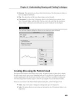
Using Illustrator’s Pathfinder Functions
The most powerful path functions in Illustrator are in the Pathfinder panel. They do tasks that
would take hours to do using Illustrator’s traditional tools and methods. The only drawback to the
Pathfinder panel is that there are so many options that it’s pretty hard to figure out which one to
use for which job. Figure 6.28 shows the Pathfinder panel.
10_584750-ch06.indd 20010_584750-ch06.indd 200 6/3/10 7:48 PM6/3/10 7:48 PM
Chapter 6: Learning How to Select and Edit
201
FIGURE 6.28
The Pathfinder panel allows you to quickly edit paths.
Add to shape area
Divide
Trim
Merge
Crop
Outline
Minus Back
Subtract from shape area
Intersect shape areas
Exclude overlapping shape areas
The Pathfinder options take over most of the mundane tasks of path editing that could otherwise
take hours. Everything that the Pathfinder options do can be done manually with other Illustrator
tools, but the Pathfinder options do them much more quickly. Common activities, such as joining
two paths together correctly and breaking a path into two pieces, are done in a snap.
The Pathfinder options change the way that two or more paths interact. The cute little symbols on
the Pathfinder options are supposed to clue you in to what each option can do, but the pictures are
small, and most don’t accurately depict exactly how each option works.
If you have the Show Tool Tips check box selected — it’s selected by default, but if it’s deselected,
choose Edit ➪ Preferences ➪ General (Illustrator ➪ Preferences ➪ General on the Mac) and then
click the Show Tool Tips check box — the name of each of the Pathfinder options appears when
you hold your cursor over its option symbol. However, these names can be a little confusing. The
names were undoubtedly chosen to signify what each of the Pathfinder options can do, but most of
them can’t be defined easily with just one word.
Setting the Pathfinder options
To access the Pathfinder options, choose Pathfinder Options from the popup menu of the
Pathfinder panel (accessed via the triangle in the upper right of the panel). This displays the
Pathfinder Options dialog box, as shown in Figure 6.29, which allows you to customize the way
that the Pathfinders work.
10_584750-ch06.indd 20110_584750-ch06.indd 201 6/3/10 7:48 PM6/3/10 7:48 PM