autocad 2007 and autocad lt 2007 bible - phần 3 ppt
Bạn đang xem bản rút gọn của tài liệu. Xem và tải ngay bản đầy đủ của tài liệu tại đây (1.96 MB, 130 trang )
218
Part II ✦ Drawing in Two Dimensions
STEPS: Extending Objects
1. Open ab10-e.dwg from the CD-ROM.
2. Save the file as
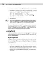
ab10-06.dwg in your AutoCAD Bible folder. It looks like Figure 10-20.
3. Choose Extend on the Modify toolbar. At the
Select objects or <select all>:
prompt, pick the line at 1 in Figure 10-20 and then press Enter.
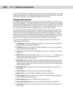
Figure 10-20: An electrical schematic.
4. At the
Select object to extend or shift-select to trim or [Fence/Crossing/
Project/Edge/Undo]: prompt, pick the line at 2 in Figure 10-20. Press Enter to finish
selecting objects. The command extends the line.
5. Repeat the EXTEND command. At the
Select objects or <select all>: prompt, pick
the lines at
3 and 4 in Figure 10-20 and then press Enter.
6. At the
Select object to extend or shift-select to trim or [Fence/Crossing/
Project/Edge/Undo]: prompt, right-click and choose Edge. Right-click and choose
Extend at the
Extend/No extend <No extend>: prompt.
7. Pick lines
3 and 4 in Figure 10-20 again at the points shown. The lines extend to meet.
Press Enter to end the command.
8. Save your drawing. It should look like Figure 10-21.
Figure 10-21: The completed electrical schematic.
4
2
3
1
17_788864 ch10.qxp 5/22/06 7:23 PM Page 218
219
Chapter 10 ✦ Editing Your Drawing with Advanced Tools
Lengthening objects
The LENGTHEN command both lengthens and shortens. It works on open objects, such as
lines, arcs, and polylines, and also increases or decreases the included angle of arcs. (You can
change the length of an arc as well as its included angle by using LENGTHEN.) AutoCAD and
AutoCAD LT offer several ways of defining the new length or included angle. Use LENGTHEN if
you want to lengthen or shorten an object when there is no available intersecting edge or
boundary to use with TRIM or EXTEND.
In the LENGTHEN command, the length of an arc is measured along its circumference. Don’t
confuse this with the Length of Chord option of the ARC command, which refers to the length
of a line stretched from one endpoint of the arc to the other endpoint.
To lengthen (or shorten) an object, choose Modify ➪ Lengthen. You cannot select
objects before the LENGTHEN command. The command responds with the
Select an
object or [DElta/Percent/Total/DYnamic]: prompt. Choose one of the following
options:
✦ Select object: This is the default. However, its purpose is to display the current mea-
surements of the object. This can help you to decide how to define the final length or
angle of the object. The current length is displayed at the command line, and the previ-
ous prompt is repeated.
✦ DElta: Right-click and choose DElta. Delta means the change, or difference, between the
current and new length or included angle. The option responds with the
Enter delta
length or [Angle] <0.0000>: prompt. If you want to change an included angle, right-
click and choose Angle. Then type the change in the included angle. Otherwise, simply
type the change in the length of the object. A positive number increases the length or
included angle. A negative number decreases the length or included angle.
✦ Percent: Right-click and choose Percent. At the
Enter percentage length
<100.0000>: prompt, type in what percent of the original object you want the final
object to be. Amounts over 100 lengthen the object. Amounts under 100 shorten the
object. You cannot change an included angle using this option.
✦ Total: Right-click and choose Total. At the
Specify total length or [Angle]
<1.0000)>: prompt, you can either choose the Angle suboption, as described for the
Delta option, or use the default total-length option. Either way, you enter the total angle
or length you want.
✦ DYnamic: Right-click and choose DYnamic. This option lets you drag the endpoint of
the object closest to where you picked it. You can use an object snap to specify the
new endpoint.
After you’ve used an option to specify the length you want, you see the
Select an object to
change or [Undo]: prompt. Here you select the object you want to change. Be sure to pick
the endpoint of the object for which you want to make the change.
The same prompt continues so that you can pick other objects by using the same length
specifications. Choose Undo to undo the last change. Press Enter to end the command.
The drawing used in the following exercise on lengthening and shortening objects, ab10-
f.dwg, is in the Drawings folder on the CD-ROM.
On the
CD-ROM
17_788864 ch10.qxp 5/22/06 7:23 PM Page 219
220
Part II ✦ Drawing in Two Dimensions
STEPS: Lengthening and Shortening Objects
1. Open ab10-f.dwg from the CD-ROM.
2. Save the file as
ab10-07.dwg in your AutoCAD Bible folder. It is a capacitor symbol
from an electrical schematic, as shown in Figure 10-22.
Figure 10-22: A poorly drawn capacitor symbol.
3. Choose Modify ➪ Lengthen and follow the prompts:
Select an object or [DElta/Percent/Total/DYnamic]: Pick the line at
1 in Figure 10-22.
Current length: 0.200
Select an object or [DElta/Percent/Total/DYnamic]: Right-click and
choose Delta.
Enter delta length or [Angle] <0.000>: .07 ↵
Select an object to change or [Undo]: Pick the line at 1 in Figure
10-22.
Select an object to change or [Undo]: ↵
This action lengthens the line.
4. Start the LENGTHEN command again and follow the prompts:
Select an object or [DElta/Percent/Total/DYnamic]: Pick the arc at 2
in Figure 10-22.
Current length: 0.407, included angle: 150
Select an object or [DElta/Percent/Total/DYnamic]: Right-click and
choose Total.
Specify total length or [Angle] <1.000)>:)>: Right-click and choose
Angle.
Specify total angle <57>: 120 ↵
Select an object to change or [Undo]: Pick the arc at 2 in Figure
10-22.
Select an object to change or [Undo]: ↵
This action shortens the arc.
2
1
17_788864 ch10.qxp 5/22/06 7:23 PM Page 220
221
Chapter 10 ✦ Editing Your Drawing with Advanced Tools
5. Save your drawing. It should look like Figure 10-23.
Figure 10-23: The completed capacitor symbol.
Stretching objects
The STRETCH command is generally used to stretch groups of objects. For example, you can
use this command to enlarge a room in a floor plan. You can also shrink objects. You can
change not only the length of the objects but the angle as well. You use a crossing window to
choose the objects to be stretched. All objects that cross the boundaries of the crossing win-
dow are stretched. All objects that lie entirely within the crossing window are merely moved.
Successful stretching involves precise placement of the crossing window. Figure 10-24 shows
the process of stretching a garage. Note that the walls that cross the boundaries of the cross-
ing window are stretched. However, the dormer that is entirely within the crossing window is
just moved. This maintains the integrity of the model.
You cannot stretch circles, text, or blocks. You can stretch arcs, although the results may not
be what you expect.
The real power of the STRETCH command is in stretching a number of objects at once.
However, you can also stretch one line. The results are similar to using the CHANGE command
to change the endpoint of a line or to editing with grips (discussed later in this chapter).
Figure 10-24: Stretching a garage.
Crossing window
Before stretching
After stretching
17_788864 ch10.qxp 5/22/06 7:23 PM Page 221
222
Part II ✦ Drawing in Two Dimensions
To stretch objects, choose Stretch from the Modify toolbar. The command responds
with the
Select objects to stretch by crossing-window or crossing-polygon . . .
instruction and then the Select objects: prompt. Create the crossing window and select
the objects that you want to stretch. (You can also use a crossing polygon — type cp at the
Select objects: prompt.) After completing the crossing window, check to see which
objects are highlighted. This helps you avoid unwanted results. You can use the object selec-
tion Remove option (type r ↵ at the command prompt) to remove objects by picking the
objects that you don’t want to stretch or move.
The STRETCH command remembers the most recent displacement throughout a session.
To stretch an object by the same displacement that you most recently used, press Enter at
the
Specify base point or [Displacement] <Displacement>: prompt. At the Specify
displacement <2.0000, 3.0000, 0.0000>: prompt, you see in angled brackets the last
displacement that you used. Press Enter to stretch the object using this displacement.
You can use multiple crossing windows to select the objects that you want to stretch. You
can also pick to select objects, although these objects are simply moved.
When you’ve finished selecting objects, you see the Specify base point or Displacement
<Displacement>: prompt. This step is just like moving objects, and you can respond in
two ways.
✦ Pick a base point. At the
Specify second point of displacement or <use first
point as displacement>: prompt, pick a second point. Object snap and PolarSnap
are helpful for picking these points.
✦ Type a displacement without using the @ sign. For example, to lengthen the objects by
6 feet in the 0-degree direction, type 6'<0 ↵. Then press Enter at the
Specify second
point of displacement or <use first point as displacement>: prompt.
Usually, you want to stretch at an orthogonal angle. If you’re going to stretch by picking, turn
ORTHO on. Object snaps, polar tracking, and Snap mode are other helpful drawing aids for
stretching.
When specifying a displacement by typing at the keyboard, you can use both positive and
negative distances. For example, 6'<180 is the same as –6'<0. Both would stretch the objects 6
feet to the left.
The drawing used in the following exercise on stretching objects, ab10-g.dwg, is in the
Drawings folder on the CD-ROM.
STEPS: Stretching Objects
1. Open ab10-g.dwg from your CD-ROM.
2. Save the file as
ab10-08.dwg in your AutoCAD Bible folder. This drawing is the plan
view of a garage, as shown in Figure 10-25. Turn on polar tracking by clicking POLAR on
the status bar. Click SNAP on the status bar and then right-click SNAP to make sure that
PolarSnap is on (the PolarSnap item will be unavailable if it is already on); otherwise,
choose PolarSnap. Turn on OSNAP and set a running object snap for endpoints.
On the
CD-ROM
Tip
Tip
17_788864 ch10.qxp 5/22/06 7:23 PM Page 222
223
Chapter 10 ✦ Editing Your Drawing with Advanced Tools
3. Choose Stretch from the Modify toolbar. At the Select objects: prompt, pick 1
in Figure 10-25. At the Specify opposite corner: prompt, pick 2. The prompt
notifies you that it found 32 objects. Press Enter to end object selection.
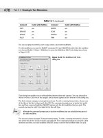
Figure 10-25: A plan view of a garage.
4. At the
Specify base point or [Displacement] <Displacement>: prompt, pick the
endpoint at the bottom-right corner of the garage. At the
Specify second point of
displacement or <use first point as displacement>: prompt, move the cursor to
the right until you see the polar tracking tooltip. Click when the tooltip says 6'-0"<0. (If
you can’t find it, type 6',0 ↵. If you’re not using Dynamic Input or have Dynamic Input
set to absolute coordinates, add the @ symbol first.) This action stretches the garage
by 6 feet.
5. Save your drawing. It should look like Figure 10-26.
Figure 10-26: The longer garage.
1
2
17_788864 ch10.qxp 5/22/06 7:23 PM Page 223
224
Part II ✦ Drawing in Two Dimensions
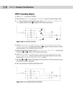
Using Construction Commands
Four additional commands are commonly used in the process of constructing models. The
BREAK command removes sections of objects at points that you specify. JOIN, a new com-
mand, joins co-linear lines, polylines, arcs, elliptical arcs, or splines. CHAMFER creates cor-
ners, and FILLET creates rounded corners.
Breaking objects
Drawing a long line and then breaking it into two or more shorter lines is often much easier
than drawing two separate lines. A common use for BREAK is to break a wall at a door or a
window in an architectural floor plan. You specify two points on the object, and the command
erases whatever is between those two points. Typically, you use object snaps to specify the
points. Sometimes, you can use TRIM to break an object, but if you have no convenient cut-
ting edge, you may find BREAK more efficient.
You can break lines, polylines, splines, xlines, rays, circles, arcs, elliptical arcs, and ellipses.
To break a line, choose Break from the Modify toolbar. You cannot select the object first.
The command responds with the
Select object: prompt. (Notice that you can only
select one object to break.) At this prompt, you have two choices:
✦ Select the object at one of the break points that you want to create. You then see the
Specify second break point or [First point]: prompt. Because you have already
specified the first point, you can now specify the second point. The command breaks
the object between the two points.
✦ Select the object by using any method of object selection. You then see the
Specify
second break point or [First point]: prompt. Right-click and choose First point. At
the
Specify first break point: prompt, pick the first break point. At the Specify
second break point: prompt, pick the second break point. The command breaks the
object between the two points.
Sometimes you may want to break an object into two pieces at a point, without eras-
ing any part of the object. Use the Break at Point button on the Modify toolbar to help
you easily break an object at a point. After selecting the object, pick where you want to break
the object at the Specify second break point or [First point]: prompt. The two
new objects look the same as before on the screen — until you select one of the objects. To
break objects at a point, AutoCAD and AutoCAD LT use @, which always signifies the last
point entered, to specify the second break point. Thus, the first and second break points are
the same.
You can use BREAK to shorten an object. Pick one point on the object where you want the
new endpoint to be. Pick the other point past its current endpoint to cut off the object at the
point you picked on the object.
Joining objects
The opposite of breaking objects is joining them. The JOIN command lets you join lines, poly-
lines, arcs, elliptical arcs, and splines. The objects must be along the same linear, circular, or
elliptical path. The objects can overlap, have a gap between them, or touch end-to-end.
Tip
17_788864 ch10.qxp 5/22/06 7:23 PM Page 224
225
Chapter 10 ✦ Editing Your Drawing with Advanced Tools
To join objects, choose Join from the Modify toolbar. Follow these prompts:
Select source object: Select the first object that you want to join.
Select lines to join to source: Select the second object. (AutoCAD
knows which type of object you’ve selected for the first prompt and
inserts it into the second prompt.) You can continue to select other
objects. Press Enter to end selection.
AutoCAD joins the objects.
A very nice touch is the ability to close arcs (to circles) and elliptical arcs (to ellipses). If your
first object is either type of arc, you see the
Select arcs to join to source or [cLose]:
prompt. Use the cLose option to close the arc.
The drawing used in the following exercise on breaking and joining objects, ab10-h.dwg, is
in the Drawings folder on the CD-ROM.
STEPS: Breaking and Joining Objects
1. Open ab10-h.dwg from your CD-ROM.
2. Save the file as
ab10-09.dwg in your AutoCAD Bible folder. This is a site plan, as
shown in Figure 10-27. Turn on OSNAP and set running object snaps for endpoint and
intersection.
3. Choose Break from the Modify toolbar. At the
Select object: prompt, pick the
line at
1. At the Specify second break point or [First point]: prompt, pick
2. This action shortens the line.
4. Repeat the BREAK command. At the
Select object: prompt, pick the circle (it’s a
maple tree) anywhere along its circumference. At the
Specify second break point
or [First point]: prompt, right-click and choose First point. At the Specify first
break point: prompt, pick the intersection at 3. At the Specify second break
point: prompt, pick the intersection at 4 to break the circle.
AutoCAD and AutoCAD LT break circles counterclockwise. If you had picked 4, and then 3,
only the smaller arc would have remained.
5. Let’s say that you decide this is a mistake. Choose Join from the Modify toolbar.
At the
Select source object: prompt, select the circle (tree) that you just broke
into an arc. At the
Select arcs to join to source or [cLose]: prompt, right-click
and choose cLose. The arc becomes a full circle again.
6. To break the line at
5, Turn on Object Snap Tracking by clicking OTRACK on the status
bar. Start the BREAK command again. Follow the prompts:
Select object: Pick the line at 5.
Specify second break point or [First point]: Right-click and choose
First point.
Specify first break point: Move the cursor to 6 to acquire it as a
tracking point. Then move the cursor to the right onto the line you
are breaking. When you see the Endpoint: Intersection tooltip, click.
(You have no visual confirmation yet that you picked the right
point.)
Note
On the
CD-ROM
17_788864 ch10.qxp 5/22/06 7:23 PM Page 225
226
Part II ✦ Drawing in Two Dimensions
Specify second break point: Move the cursor to 7 to acquire it as a
tracking point. Then move the cursor onto the line you are breaking.
At the Endpoint: 4'-2 3/4"<0.0000 tooltip, click.
Figure 10-27: A site plan.
7. Start the JOIN command. At the
Select source object: prompt, select the line at 8.
At the
Select lines to join to source: prompt, select the line at 9. Press Enter to
end selection and join the lines into one.
8. Save your drawing. It should look like Figure 10-28.
Figure 10-28: The edited site plan.
7
5
6
3
8
9
1
4
2
17_788864 ch10.qxp 5/22/06 7:23 PM Page 226
227
Chapter 10 ✦ Editing Your Drawing with Advanced Tools
For AutoCAD only: Two AutoLISP programs on the CD-ROM can help you with breaking and
unbreaking objects. Pend puts a break line at the end of a pipe. See \Software\Chapter
10\Pend. Br draws a line with a break symbol. See \Software\Chapter 10\Br.
The Express Tools contain a command, BREAKLINE, to create a break symbol. Choose
Express ➪ Draw ➪ Break-Line Symbol. Another Express Tools command, OVERKILL (available
on the command line), deletes objects that are on top of other objects.
Creating chamfered corners
The CHAMFER command creates corners from two nonparallel lines. You can also chamfer
xlines, rays, and polylines. You can simply extend the lines to meet at an intersection (a
square corner), or create a beveled edge. If you create a beveled edge, you define the edge by
either two distances or one distance and an angle relative to the first line that you’re chamfer-
ing. Figure 10-29 shows the elements of a chamfered corner.
Figure 10-29: A chamfered corner.
Chamfering is a two-step process. First you define how you want to chamfer the corner, speci-
fying either two distances from the corner or a distance and an angle. Then you select the
two lines that you want to chamfer.
To chamfer, choose Chamfer from the Modify toolbar. You cannot select objects before the
CHAMFER command. The command responds with the
(TRIM mode) Current chamfer
Dist1 = 0.0000, Dist2 = 0.0000 Select first line or [Undo/Polyline/Distance/Angle/
Trim/mEthod/Multiple]: prompt. The command starts by listing the current settings. (The
CHAMFER command remembers the last-used chamfer data.) You can define two distances
from a corner or one distance and an angle:
✦ To define two distances from the corner, right-click and choose Distance. At the
Specify first chamfer distance <0.0000>: prompt, type the first chamfer distance
or press Enter to accept the default (which is the last distance that you defined). At the
Specify second chamfer distance <0.0000>: prompt, type the second distance. The
default for this is always the first chamfer distance because equal chamfer distances
are so common.
Second line
Second chamfer distance
First chamfer
distance
First line
Chamfer angle
On the
CD-ROM
17_788864 ch10.qxp 5/22/06 7:23 PM Page 227
228
Part II ✦ Drawing in Two Dimensions
✦ To define a distance (from the corner) and an angle, right-click and choose Angle. At
the
Specify chamfer length on the first line <1.0000>: prompt, enter a distance.
This is the same as the first chamfer distance. At the
Specify chamfer angle from the
first line <0>: prompt, type the angle between the first line and the chamfer line.
Now that you have specified the settings that you want, you’re ready to chamfer. Your dis-
tances or distance and angle are displayed as you just specified them. The command repeats
the
Select first line or [Undo/Polyline/Distance/Angle/Trim/mEthod/Multiple]:
prompt. Select the first line. If you aren’t creating a chamfer with equal distances, the order in
which you select the lines is important. The command trims the first line selected by the first
distance, and the second line selected based on either the second distance or the angle. At
the
Select second line: prompt, select the second line to chamfer the lines.
If the lines already intersect, the command trims them to create a corner. The pick points on
intersecting lines should be on the part of the lines that you want to keep, not on the part of
the lines that you want to trim off.
To quickly create a square corner if you have non-zero settings, press Shift as you select the
second line. Of course, you can still set each distance to zero.
Choose the Polyline option to chamfer an entire polyline at once. Chapter 16 covers poly-
lines, and Chapter 24 discusses chamfering 3D models.
By default, CHAMFER trims the original lines that it chamfers. If you want to keep the full orig-
inal lines when you add the chamfer line, choose the Trim option and choose No Trim. Use
the Multiple option to continue the prompts and chamfer several corners in one command.
The new Undo option lets you undo your last chamfer and try again.
The drawing used in the following exercise on chamfering lines, ab10-i.dwg, is in the
Drawings folder on the CD-ROM.
STEPS: Chamfering Lines
1. Open ab10-i.dwg from your CD-ROM.
2. Save the file as
ab10-10.dwg in your AutoCAD Bible folder. This drawing is a very
small section of a “porcupine” mixer, as shown in Figure 10-30.
3. Choose Chamfer from the Modify toolbar. CHAMFER states the current mode and
distances. At the
Select first line or [Undo/Polyline/Distance/Angle/
Trim/mEthod/Multiple]: prompt, pick 1 in Figure 10-30. At the Select second
line: prompt, pick 2. (If the current distances are not zero, press Shift as you pick
2.)The command chamfers the two lines to make a corner. (If this doesn’t work, you
may have the Trim option set to No Trim. Change the setting to Trim and try again.)
4. Repeat the CHAMFER command. Follow the prompts:
Select first line or [Polyline/Distance/Angle/Trim/Method/mUltiple]:
Right-click and choose Angle.
Specify chamfer length on the first line <1>: 9/16 ↵
Specify chamfer angle from the first line <0>: 45 ↵
On the
CD-ROM
Cross-
Reference
Tip
17_788864 ch10.qxp 5/22/06 7:23 PM Page 228
229
Chapter 10 ✦ Editing Your Drawing with Advanced Tools
Figure 10-30: A mechanical drawing showing a small section of a “porcupine”
mixer.
5. At the Select first line or [Undo/Polyline/Distance/Angle/Trim/Method/
mUltiple]: prompt, pick 3 in Figure 10-30. At the Select second line: prompt, pick
4. The command chamfers the two lines, as shown in Figure 10-31.
6. Save your drawing.
Figure 10-31: The edited drawing after using the CHAMFER command.
Creating rounded corners
The FILLET command creates rounded corners, replacing part of two lines with an arc. Fillets
are often used in mechanical drawings. In certain cases, you can use FILLET instead of the
ARC command to create arcs. As with CHAMFER, you can fillet lines, xlines, rays, and poly-
lines — they can even be parallel. You can also fillet circles, arcs, elliptical arcs, and ellipses.
3
2
1
4
17_788864 ch10.qxp 5/22/06 7:23 PM Page 229
230
Part II ✦ Drawing in Two Dimensions
The FILLET command defines the fillet arc by its radius, as shown in Figure 10-32.
Figure 10-32: A fillet consisting of two lines and an arc.
Like chamfering, filleting is a two-step process. First you define the radius of the fillet arc.
Then you select the two lines that you want to fillet. You cannot select objects before the FIL-
LET command.
To fillet, follow these steps:
1. Choose Fillet from the Modify toolbar. The command responds with the
Current
settings: Mode = TRIM, Radius = 0.0000 Select first object or [Undo/
Polyline/Radius/Trim/Multiple]: prompt.
2. Right-click and choose Radius.
3. At the
Specify fillet radius <0.0000>: prompt, type the radius you want. The
default is either 0.0000 or the last radius that you specified.
4. The command repeats the
Select first object or [Undo/Polyline/Radius/Trim/
Multiple]: prompt. Select the first object that you want to fillet.
5. At the
Select second object or shift-select to apply corner: prompt, select the
second object that you want to fillet. This action creates the fillet.
By default, FILLET trims the original lines that it fillets, but the FILLET command recalls the
last setting you used. If you want to keep the full original lines when you create a fillet, right-
click and choose the Trim option, and then choose No Trim.
Choose the Polyline option to fillet an entire polyline at once. Chapter 16 covers polylines,
and Chapter 24 discusses filleting 3D models.
Filleting with a zero radius gives the same results as chamfering with distances set to zero.
(See the previous section on chamfering.) If your existing settings are non-zero, you can press
Shift as you select the second object to create a square corner.
The order in which you select the two objects to be filleted is not important. However, where
you pick the objects is quite important. If two objects intersect, the command keeps the
objects on the same side of the intersection as your pick point and fillets them. Those parts
of the objects on the far side of the intersection are erased.
When you fillet arcs and lines, if more than one fillet is possible, FILLET connects the end-
points closest to your pick points. Filleting circles and lines can produce unexpected results.
Sometimes you need to experiment to find the proper pick points.
Use the Multiple option to continue the prompts and fillet several corners in one command.
Tip
Cross-
Reference
Radius
Arc center
Fillet arc
17_788864 ch10.qxp 5/22/06 7:23 PM Page 230
231
Chapter 10 ✦ Editing Your Drawing with Advanced Tools
The drawing used in the following exercise on filleting objects, ab10-i.dwg, is in the
Drawings folder on the CD-ROM.
STEPS: Filleting Objects
1. Open ab10-i.dwg from your CD-ROM.
2. Save the file as
ab10-11.dwg in your AutoCAD Bible folder. This is the same drawing
used in the previous exercise. It is shown in Figure 10-33.
Figure 10-33: A mechanical drawing showing a small section of a “porcupine”
mixer.
3. Choose Fillet from the Modify toolbar. At the
Select first object or [Undo/
Polyline/Radius/Trim/Multiple]: prompt, right-click and choose Radius. At
the
Specify fillet radius <1/2>: prompt, type 5/8 ↵.
4. At the
Select first object or [Undo/Polyline/Radius/Trim/Multiple]: prompt,
pick the line at
1 in Figure 10-33. At the Select second object or shift-select to
apply corner: prompt, pick the line at 2 to fillet the two lines.
5. Repeat the FILLET command. At the
Select first object or [Undo/Polyline/
Radius/Trim/ Multiple]: prompt, right-click and choose Radius. At the Enter
fillet radius <5/8>: prompt, type 1/4 ↵.
6. At the
Select first object or [Undo/Polyline/Radius/Trim/Multiple]: prompt,
right-click and choose mUltiple. Pick the line at
3 in Figure 10-33. At the Select
second object or shift-select to apply corner: prompt, pick the line at 4 to fillet
the two lines. The prompts continue. This time pick at
5 and 6.
7. If you want, you can connect the two loose lines that the fillets created and create some
more fillets in the drawing.
8. Save your drawing. It should look like Figure 10-34.
1
2
3
4
5
6
On the
CD-ROM
17_788864 ch10.qxp 5/22/06 7:23 PM Page 231
232
Part II ✦ Drawing in Two Dimensions
Figure 10-34: The filleted drawing.
Creating a Revision Cloud
You may need to mark areas of your drawings that contain revisions in order to draw atten-
tion to these revisions. A common method is to draw a revision cloud around the revised
objects. Figure 10-35 shows a drawing with a revision cloud, which is a series of arcs that indi-
cate that an area of the drawing has been revised.
Figure 10-35: The revision cloud shows where the drawing has been modified.
17_788864 ch10.qxp 5/22/06 7:23 PM Page 232
233
Chapter 10 ✦ Editing Your Drawing with Advanced Tools
To create a revision cloud, follow these steps:
1. Choose Revcloud from the Draw toolbar.
2. At the
Specify start point or [Arc length/Object/Style] <Object>: prompt, you
can choose three options:
• To change the length of the arc, right-click and choose Arc Length. Then specify
a new arc length. For a variable, hand-drawn look, you can specify a minimum
arc length and a maximum arc length that is up to three times the length of the
minimum.
• To change a closed object into a revision cloud, right-click and choose Object.
Then pick a circle, ellipse, closed polyline, or closed spline. You can choose to
reverse the direction of the revision cloud. The object is converted to a revision
cloud, and the command ends.
• To choose from two available cloud styles, right-click and choose Style. At the
next prompt, choose either the Normal or Calligraphy option. A calligraphy revi-
sion cloud has a variable line width so that it looks as if you drew it with a callig-
raphy pen.
3. Click where you want the revision cloud to start. You also see an instruction,
Guide
crosshairs along cloud path. . ., which means that you don’t have to pick to create
the arcs. You just have to move the crosshairs along the path of the desired cloud.
4. Move the crosshairs counterclockwise to create a circular or elliptical shape. When you
approach the start point, the command ends automatically. (You can end the cloud at
any time by pressing Enter.)
If you want, you can pick each arc endpoint to control the size of the arcs. However, if you
move the crosshairs farther than the arc length, an arc is created automatically. REVCLOUD
multiplies the arc length by the Overall Scale factor (see Chapter 15) to adjust for different
scale factors.
Hiding Objects with a Wipeout
A wipeout covers existing objects in order to clear space for some annotation or to indicate
that the covered objects will be changed and should therefore be ignored. A wipeout is a
polygonal area with a background that matches the background of the drawing area. The
WIPEOUT command creates a polygon of the same color as the background of your drawing
area.
To create a wipeout, follow these steps:
1. Choose Draw ➪ Wipeout.
2. At the
Specify first point or [Frames/Polyline] <Polyline>: prompt, specify the
first point of a shape that will cover existing objects. To use a polyline as the shape,
right-click and choose Polyline. (The polyline can’t contain any arcs when you use it for
this purpose.) Then select the polyline and choose whether or not to erase the polyline.
3. At the
Specify next point or [Undo]: prompt, if you specified a point, specify the
next point.
Note
17_788864 ch10.qxp 5/22/06 7:23 PM Page 233
234
Part II ✦ Drawing in Two Dimensions
4. At the Specify next point or [Close/Undo]: prompt, specify another point or use
the Close option to close the wipeout shape. You can also press Enter to end the com-
mand and use the shape that you specified.
By default, the wipeout has a frame around it, using the current layer’s color. You can hide the
frames of all wipeouts by starting the WIPEOUT command, choosing the Frames option, and
then choosing Off.
You can create a background mask especially for text. This mask covers a rectangle around
your text so that you can read the text more easily. For more information, see Chapter 13.
Double-Clicking to Edit Objects
You can double-click objects to edit them. What happens after you double-click depends on
the type of object. In most cases, double-clicking an object just opens the Properties palette
where you can change the object’s properties. For example, double-clicking a polyline does
not start the PEDIT command, which is a command for editing polylines. For more informa-
tion about using the Properties palette, see “Editing with the Properties Palette” later in this
chapter.
When you double-click certain types of objects in a drawing, you see a dialog box that is spe-
cific to these objects:
✦ Attribute definition: Opens the Edit Attribute Definition dialog box (the DDEDIT com-
mand). See Chapter 18 for more information.
✦ Attribute within a block: Opens the Enhanced Attribute Edit dialog box (the EATTEDIT
command) in AutoCAD and the Edit Attributes dialog box (the ATTEDIT command) in
AutoCAD LT. See Chapter 18 for more information.
✦ Block: In AutoCAD, opens the Edit Block Definition dialog box. You can choose the
block from a list and click OK to enter the Block Editor. (See Chapter 18 for more infor-
mation.)
✦ Hatch: Opens the Hatch Edit dialog box (the HATCHEDIT command). See Chapter 16
for more information.
✦ Mline: Opens the Multilines Edit Tools dialog box (the MLEDIT command). Mlines are
not available in AutoCAD LT, which has a similar feature, called Dlines. See Chapter 16
for more information.
✦ Mtext or leader text: Opens the Multiline Text Editor (the MTEDIT command). See
Chapter 13 for more information.
✦ Text (TEXT or DTEXT commands): Opens the Edit Text dialog box (the DDEDIT com-
mand). See Chapter 13 for more information.
✦ Xref: Opens the Reference Edit dialog box (the REFEDIT command) in AutoCAD. In
AutoCAD LT, displays the Properties palette. See Chapter 19 for more information.
You can customize what happens when you double-click an object. For example, you could
choose to display the Properties palette instead of the Reference Edit dialog box when you
double-click an xref. See Chapter 33 for details.
Cross-
Reference
Cross-
Reference
17_788864 ch10.qxp 5/22/06 7:23 PM Page 234
235
Chapter 10 ✦ Editing Your Drawing with Advanced Tools
The DBLCLKEDIT command specifies whether double-clicking opens a dialog box in these
instances. To turn off double-clicking to edit objects, choose Tools➪ Options and click the
User Preferences tab. Uncheck the Double Click Editing check box in the Windows Standard
Behavior section of the dialog box.
Grips
Grips offer a way to edit objects without choosing commands. By using grips, you can quickly
stretch, move, rotate, scale, copy, and mirror objects.
When you select an object without first choosing a command, the object appears highlighted
with grips — small boxes at preset object snap points. (If you don’t see grips, they may be
turned off. See the “Customizing grips” section later in this chapter to find out how to turn
them back on.) You can continue to select more objects in this way.
You then click to activate a grip and use the grip to manipulate the object. When the grip is
activated, it turns red (by default). An activated grip is also called a hot grip, as shown in
Figure 10-36. In some cases, you activate more than one grip at a time. To activate more than
one grip, hold down Shift and then click the grips. If you activate a grip in error, click it again
to deactivate it. Grips are so called because you can “hold on to” the object by dragging the
grips with the mouse.
After you activate a grip, right-click with the mouse to open the Grip shortcut menu, which
lists all of the grip options.
Figure 10-36: Moving a line. Grips appear
at preset object snaps. You use the hot
grip to manipulate an object.
Hot grip (red)
Grip (blue)
Grip (blue)
Line's new
position
Line's original
position
Crosshairs
17_788864 ch10.qxp 5/22/06 7:23 PM Page 235
236
Part II ✦ Drawing in Two Dimensions
You can also press the Spacebar or Enter to cycle through five possible commands on the
command line. As long as you’re familiar with the STRETCH, MOVE, ROTATE, SCALE, and
MIRROR commands, you can easily learn how to accomplish the same edits by using grips
because the prompts are so similar. After you complete the edit, the object remains high-
lighted and the grips remain, so that you can further edit the object. If you want to edit
another object, press Esc once to remove the grips. Then select another object or objects or
choose another command.
If you use Dynamic Input, you can customize how many and which tooltips appear when you
grip edit. Right-click the DYN button on the status bar and choose Settings to open the
Drafting Settings dialog box with the Dynamic Input tab on top (I explain this dialog box in
the “Specifying Dynamic Input settings” section of Chapter 4). Click the Settings button in the
Dimension Input section to open the Dimension Input Settings dialog box. The settings here
apply to grip editing. By default, the Show Two Dimension Input Fields at a Time option is
selected. Although this setting usually works well, you can go down to one input field or
specify additional fields. When you select multiple grips to edit an object, no Dynamic Input
field appears.
Stretching with grips
Stretching with grips involves understanding how the grip points relate to the object. For
example, you cannot stretch a line from its midpoint — if you think about it, there’s no way to
define in which direction to stretch the line. Also, you cannot stretch a circle, you can only
scale it. Aside from these types of limitations, anything goes.
Stretching one line
You can stretch one line. The result is similar to using the CHANGE command to change a
line’s endpoint. To stretch a line, select it, and click the grip at the endpoint that you want to
stretch. The prompt on the command line responds with
** STRETCH **
Specify stretch point or [Base point/Copy/Undo/eXit]:
STRETCH is the first grip-editing command on the command line. Simply specify the new end-
point for the line, using any method of specifying a coordinate, to stretch the line. The other
options work as follows:
✦ Base point lets you define a base point — other than the activated grip — and a second
point. Right-click to open the Grip shortcut menu and choose Base Point. The option
displays the
Specify base point: prompt. Define a base point. Again you see the orig-
inal
Specify stretch point or [Base point/Copy/Undo/eXit]: prompt. Define the
second stretch point to stretch the line.
✦ Copy puts you in Multiple mode. Right-click to open the Grip shortcut menu and
choose Copy. Again you see the original
Specify stretch point or [Base point/
Copy/Undo/eXit]: prompt. Specify a new point to keep the original line, and create a
new line stretched to the new point. You can continue to create new stretched lines.
✦ Undo undoes the last edit. Right-click to open the Grip shortcut menu and choose
Undo.
Note
17_788864 ch10.qxp 5/22/06 7:23 PM Page 236
237
Chapter 10 ✦ Editing Your Drawing with Advanced Tools
✦ eXit returns you to the Command prompt. Right-click to open the Grip shortcut menu
and choose Exit. Esc also returns you to the Command prompt.
Stretching multiple lines
Stretching more than one line at a time is similar to the most common use of the STRETCH
command. However, it can also be somewhat confusing.
As explained earlier in this chapter, when you use the STRETCH command, objects that cross
the crossing window are stretched, while objects entirely within the crossing window are
moved. When you stretch multiple lines, you should activate endpoint grips to stretch lines,
and activate midpoint grips to move lines. Picking all of those grips accurately can be difficult
and time-consuming. Also, small objects that are close together create a lot of overlapping grips
that are hard to select. For this reason, stretching multiple lines works best with simple models.
To stretch multiple lines, follow these steps:
1. Choose the objects that you want to stretch. The objects are highlighted and display
grips. You can use any method of choosing objects — you are not limited to crossing
windows.
2. Hold down Shift and pick each grip that you want to stretch. If there are internal
objects that you want to move with the stretch, select their grips, too; these include
the midpoints of the lines and arcs, and the centers of the circles.
3. Release Shift and pick a grip to use as a base point. You see the prompt:
** STRETCH **
Specify stretch point or [Base point/Copy/Undo/eXit]:
4. Specify a new stretch point. You can also use any of the other options.
At the end of this section on grips, you have the opportunity to try them out in an exercise.
Moving with grips
It’s easy to move objects with grips. First, choose all of the objects that you want to move.
Then click any grip to activate it. This becomes the base point. Right-click to open the Grip
shortcut menu and choose Move.
You can also press the Spacebar to cycle through the grip editing modes. For example, to
move an object, press the Spacebar once.
After you choose Move editing mode, you see the prompt:
** MOVE **
Specify move point or [Base point/Copy/Undo/eXit]:
Use any method to specify the second point. Be sure to use @ if you’re typing in relative coor-
dinates. The selected objects move. The other options work as follows:
✦ Base point lets you define a base point, other than the activated grip. Right-click to
open the Grip shortcut menu and choose Base Point. You see the
Specify base point:
prompt. Define a base point. The original Specify move point or [Base point/Copy/
Undo/eXit]: prompt returns. Define the second move point to move the objects.
Tip
17_788864 ch10.qxp 5/22/06 7:23 PM Page 237
238
Part II ✦ Drawing in Two Dimensions
✦ Copy puts you in Multiple mode and lets you copy objects. Right-click to open the Grip
shortcut menu and choose Copy (or type c ↵). You see the original
Specify move
point or [Base point/Copy/Undo/eXit]: prompt. Specify a new point to keep the
original object and create a new object where you specify. You can continue to create
new objects.
✦ Undo undoes the last edit. Right-click to open the Grip shortcut menu and choose
Undo.
✦ eXit returns you to the Command prompt. Right-click to open the Grip shortcut menu
and choose Exit. Esc also returns you to the Command prompt.
Rotating with grips
Rotating with grips is very similar to using the ROTATE command. First, choose all of the
objects that you want to rotate. Then click any grip to activate it. This becomes the base
point. Right-click to open the Grip shortcut menu and choose Rotate. You see the prompt:
** ROTATE **
Specify rotation angle or [Base point/Copy/Undo/Reference/eXit]:
Type in a rotation angle or pick a point to rotate the objects. The other options work as fol-
lows:
✦ Base point lets you define a base point, other than the activated grip. Right-click to
open the Grip shortcut menu and choose Base Point. You see the
Specify base
point: prompt. Define a base point. The original Specify rotation angle or [Base
point/Copy/Undo/Reference/eXit]: prompt returns. Specify the rotation angle to
rotate the objects.
✦ Copy puts you in Multiple mode and lets you copy objects. Right-click to open the Grip
shortcut menu and choose Copy. Again, you see the original
Specify rotation angle
or [Base point/Copy/Undo/Reference/eXit]: prompt. Specify a rotation angle to
keep the original object and create a new rotated object where you specified. You can
continue to create new objects.
✦ Undo undoes the last edit. Right-click to open the Grip shortcut menu and choose
Undo.
✦ Reference lets you specify both a reference angle and a new angle. Right-click to open
the Grip shortcut menu and choose Reference. You see the
Specify a Reference
angle <0>: prompt. Type an angle or pick two points to specify an angle. The Specify
new angle or [Base point/Copy/Undo/Reference/eXit]: prompt appears. Type an
angle or pick a point. This works like the Reference option for the ROTATE command.
(See Chapter 9.)
✦ eXit returns you to the Command prompt. Right-click to open the Grip shortcut menu
and choose Exit. Esc also returns you to the Command prompt.
Scaling with grips
Scaling with grips is very similar to using the SCALE command. First, choose all of the objects
that you want to scale. Then click any grip to activate it. This becomes the base point. Right-
click to open the Grip shortcut menu and choose Scale. You see the prompt:
17_788864 ch10.qxp 5/22/06 7:23 PM Page 238
239
Chapter 10 ✦ Editing Your Drawing with Advanced Tools
** SCALE **
Specify scale factor or [Base point/Copy/Undo/Reference/eXit]:
Type a scale factor to scale the objects. The other options work as follows:
✦ Base point lets you define a base point, other than the activated grip. Right-click to
open the Grip shortcut menu and choose Base Point. You see the S
pecify base
point: prompt. Define a base point. The original Specify scale factor or [Base
point/Copy/Undo/Reference/eXit]: prompt appears. Define the scale factor to
scale the objects.
✦ Copy puts you in Multiple mode and lets you copy objects. Right-click to open the Grip
shortcut menu and choose Copy. You see the original
Specify scale factor or [Base
point/Copy/Undo/Reference/eXit]: prompt. Specify a scale factor to keep the origi-
nal object and create a new scaled object. You can continue to create new scaled
objects.
✦ Undo undoes the last edit. Right-click to open the Grip shortcut menu and choose
Undo.
✦ Reference lets you specify a reference length and a new scale. Right-click to open the
Grip shortcut menu and choose Reference. You see the
Specify reference length
<0>: prompt. Type a length or pick two points to specify a length. You see the Specify
new length or [Base point/Copy/Undo/Reference/eXit]: prompt. Type a length or
pick a point. This works like the Reference option for the SCALE command. (See
Chapter 9.)
✦ eXit returns you to the Command prompt. Right-click to open the Grip shortcut menu
and choose Exit. Esc also returns you to the Command prompt.
Mirroring with grips
Mirroring with grips is similar to using the MIRROR command. First, choose all of the objects
that you want to mirror. Then click any grip to activate it. This becomes the first point of the
mirror line. Right-click to open the Grip shortcut menu. Choose Mirror. You see the prompt:
** MIRROR **
Specify second point or [Base point/Copy/Undo/eXit]:
Specify the second point of the mirror line to mirror the objects.
By default, AutoCAD and AutoCAD LT erase the original objects. To keep the original objects,
you must use the Copy option. This feature is the opposite of the MIRROR command, where
the default is to keep the original objects.
The other options work as follows:
✦ Base point lets you define a base point, other than the activated grip, as well as a sec-
ond point. Right-click to open the Grip shortcut menu and choose Base Point. You see
the
Specify base point: prompt. Define a base point—that is, the first point of the
mirror line. The original
Specify second point or [Base point/Copy/Undo/eXit]:
prompt appears. Define the second point of the mirror line to mirror the objects.
Caution
17_788864 ch10.qxp 5/22/06 7:23 PM Page 239
240
Part II ✦ Drawing in Two Dimensions
✦ Copy puts you in Multiple mode and lets you keep the original objects. Right-click to
open the Grip shortcut menu and choose Copy. You see with the original
Specify
second point or [Base point/Copy /Undo/eXit]: prompt. Specify the second point
to keep the original objects and create new mirrored objects. You can continue to
create new mirrored objects.
✦ Undo undoes the last edit. Right-click to open the Grip shortcut menu and choose Undo.
✦ eXit returns you to the Command prompt. Right-click to open the Grip shortcut menu
and choose Exit. Esc also returns you to the Command prompt.
The drawing used in the following exercise on editing with grips, ab10-j.dwg, is in the
Drawings folder on the CD-ROM.
STEPS: Editing with Grips
1. Open ab10-j.dwg from the CD-ROM.
2. Save the file as
ab10-12.dwg in your AutoCAD Bible folder. This is a small section of a
drive block, seen from above, as shown in Figure 10-37. Make sure that ORTHO and
OSNAP are on.
3. Use a selection window to select the entire model. Now hold down Shift and place a
selection window around the small circles and rectangle at the center of the model to
deselect them.
4. Pick the grip at
1 in Figure 10-37 to activate it. You see the following prompt:
** STRETCH **
Specify stretch point or [Base point/Copy/Undo/eXit]:
5. Right-click and choose Mirror from the shortcut menu. You see the following prompt:
** MIRROR **
Specify second point or [Base point/Copy/Undo/eXit]:
6. Right-click and choose Copy so that the original objects that you mirror are not
deleted.
7. At the
Specify second point or [Base point/Copy/Undo/eXit]: prompt, move the
cursor to the right. You can see the mirror image of the model. Pick any point to the
right (in the 0-degree direction) of the activated grip.
Figure 10-37: This small section of a drive block, seen from
above, can be edited with grips.
2
1
On the
CD-ROM
17_788864 ch10.qxp 5/22/06 7:23 PM Page 240
241
Chapter 10 ✦ Editing Your Drawing with Advanced Tools
8. Right-click and choose Exit to return to the command line. The original objects are still
highlighted.
9. Use a large selection window to select all of the new objects, including the small rectan-
gle and circles in the middle. Everything (old and new) should be highlighted and dis-
play grips.
10. Pick the grip at
2 in Figure 10-37 to activate it. Right-click and choose Rotate from the
shortcut menu. At the
Specify rotation angle or [Base
point/Copy/Undo/Reference/eXit]: prompt, type 90 ↵. This action rotates the
model.
11. Pick the bottom-right grip to activate it. Right-click and choose Scale from the shortcut
menu. At the
Specify scale factor or [Base point/Copy/Undo/Reference/eXit]:
prompt, type .5 ↵. This action scales the model.
12. Pick the grip at the midpoint of the bottom line. Right-click and choose Move from the
shortcut menu. At the
Specify move point or [Base point/Copy/Undo/eXit]:
prompt, type @0,–3 ↵. The model should look like Figure 10-38.
Figure 10-38: The drive block section,
after several grip edits, looks a little like
a cookie jar.
13. Press Esc to remove all grips. Define a crossing window by picking first at
1, and then
at
2 (see Figure 10-38).
14. Hold down Shift and pick all of the grips along the bottom three lines. Release Shift and
pick the grip at the middle of the bottom line. At the
Specify stretch point or [Base
point/Copy/Undo/eXit]: prompt, type @0,1 ↵ to shrink the model.
If the stretch does not come out right (it might be hard to see and activate all of the
grips), choose Undo from the Standard toolbar to undo the stretch and try again.
15. Save your drawing.
1
2
17_788864 ch10.qxp 5/22/06 7:23 PM Page 241
242
Part II ✦ Drawing in Two Dimensions
Customizing grips
You can turn grips on and off and customize their size and color. Choose Tools ➪ Options and
click the Selection tab to open the dialog box shown in Figure 10-39.
Figure 10-39: Use the Selection tab of the Options dialog box to
customize grips.
By default, grips are enabled. Also by default, grips are turned off for blocks. (Chapter 18 cov-
ers blocks.) When grips are off for blocks, you see only one grip when you select a block; this
is its insertion point. When grips for blocks are on, you see all of the grips you would nor-
mally see for objects.
In the Grips section, you can choose the colors that you want for unselected and selected
(hot) grips. Click the drop-down lists to choose a color.
The Grip Size section lets you drag the slider bar to set the size of the grips. Click OK after
you have made the desired changes.
Editing with the Properties Palette
The Properties palette displays the properties of selected objects. You can also use the
Properties palette to change the properties of objects.
To open the Properties palette, click Properties on the Standard toolbar, choose Tools ➪
Palettes ➪ Properties, or press Ctrl+1. The Properties palette, shown in Figure 10-40,
opens on your screen.
17_788864 ch10.qxp 5/22/06 7:23 PM Page 242