autocad 2008 autocad lt 2008 no experience required - phần 6 pot
Bạn đang xem bản rút gọn của tài liệu. Xem và tải ngay bản đầy đủ của tài liệu tại đây (1.5 MB, 73 trang )
3. Erase all the circles, letters, and numbers in the grid except those for
A and 1. Leave the grid lines intact (see Figure 9.1).
FIGURE 9.1: The floor plan of Cabin8e with all but two grid symbols erased
FIGURE 9.2: The Properties palette for the text
4. Select the letter A, right-click, and
then choose Properties from the
context menu. The Properties
palette displays information about
the text (see Figure 9.2). You need
to know the text style and height:
Label and 1'-0".
5. Close or minimize the Properties
palette, and then erase A and 1, but
not the circles.
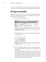
6. Start the Scale command. Select the
circle on the top, and press ↵.
Using Attributes for a Grid 341
26531ch09.qxd 3/30/07 6:11 PM Page 341
7. Use the Endpoint osnap, and pick the endpoint of the grid line where
it meets the circle. Enter 1.25↵. This enlarges the circle.
8. Repeat steps 6 and 7 for the circle on the left side.
9. Choose Draw
➣ Block ➣ Define Attributes to open the Attribute Defi-
nition dialog box (see Figure 9.3). In the Attribute area are three text
boxes: Tag, Prompt, and Default. The cursor is flashing in the Tag text
box. Think of the letter in the grid circle. It’s a grid letter, which is a
tag that provides the visual textual information.
FIGURE 9.3: The Attribute Definition dialog box
10. Enter grid_letter. Don’t press ↵.
11. Press the Tab key to move to the Prompt text box. Here you enter a
prompt, which will ask the future user who will be setting up a grid,
for the text to input for the tag.
12. Enter Enter grid letter. Press Tab to move to the Default text box.
Here you enter a default or sample value that is used if the future
user presses ↵ instead of entering a new value. You want it capitalized
in this case, so enter A. This sets up the attribute so that the drafter
setting up the grid will be prompted to enter the grid letter and will
be given a default of A. The capital A lets the user know that the letter
should be uppercase.
Chapter 9 • Using Dynamic Blocks and Tables342
26531ch09.qxd 3/30/07 6:11 PM Page 342
13. The lower portion of the dialog box is where you set up parameters
for the attribute text: location in the drawing, justification, text style,
height, and rotation. Click the Justification drop-down list, and select
Middle Center.
14. Choose Label in the Text Style list box. Because the Label text style’s
height is set to a value other than 0'0", the Text Height text box in the
Attribute Definition dialog box is grayed out. Figure 9.4 shows what
you should see.
FIGURE 9.4: The Attribute Definition dialog box showing the appropri-
ate values
15. Click OK. Doing so returns you to the drawing to pick an insertion
point. Back in the drawing, use the Center osnap, and click the circle
at the top of the grid. GRID_LETTER is centered over the circle (see
Figure 9.5), and the Attdef command ends.
The text over the circle is called the attribute definition. Its function in Auto-
CAD is similar to that of a block definition. When you made the win-1 block for
the windows, the definition was a 12"-long window with an insertion point.
When the win-1 block is inserted, you can use the original block definition to
make windows of various sizes. The same is true for the attribute definition.
When it becomes part of a block that’s inserted, the attribute can be any letter
you want. You’ll see that happen in a minute.
Using Attributes for a Grid 343
26531ch09.qxd 3/30/07 6:11 PM Page 343
FIGURE 9.5: The first attribute definition placed in the grid circle
First, make a similar attribute definition for the numbered grid symbol:
1. Enter att↵ to start the Attribute Definition command. The Attribute
Definition dialog box opens again.
2. Repeat steps 10–15 in the preceding exercise, using the following
guidelines:
a. Enter grid_number in the Tag text box.
b. Enter Enter grid number in the Prompt text box.
c. Enter 1 in the Default text box.
d. Select Middle Center from the Justification drop-down list.
e. Click OK, use the Center osnap, and click the grid circle on
the left.
The second attribute definition is centered over the circle on the left side (see
Figure 9.6).
Chapter 9 • Using Dynamic Blocks and Tables344
26531ch09.qxd 3/30/07 6:11 PM Page 344
FIGURE 9.6: The second attribute definition is placed.
You now have two attribute definitions and are ready to make each of them
part of a block that includes the circle over which they’re currently centered.
Defining Blocks with Attributes
You have to define two blocks for the grid symbols and their attributes. The
insertion point for the block used for the top of the grid should be at the lowest
point of the circle. The insertion point for the block used for the left side should
be at the point on the circle farthest to the right. Follow these steps:
1. Click the Make Block button on the Draw toolbar to start the Block
command, and open the Block Definition dialog box.
2. In the Name drop-down list, enter grid-v (for vertical) in the blank
space, and then click the Pick Point button in the Base Point area.
3. In the drawing, use the Endpoint osnap, and select the grid line that
ends at the circle on top.
4. In the Block Definition dialog box that reopens, click the Select
Objects button in the Objects area.
5. In the drawing, select the circle and attribute definition on the top.
Press ↵.
Using Attributes for a Grid 345
26531ch09.qxd 3/30/07 6:11 PM Page 345
6. In the Block Definition dialog box, be sure the Delete button is
selected in the Objects area, and click OK. The block is defined and
includes the attribute definition. In the drawing, the top circle and
attribute definition have been deleted.
7. Start the Block command again. Repeat steps 2–6 to define a second
block for the circle and attribute definition on the left side. Use the
following guidelines:
a. Enter grid-h in the Name drop-down list.
b. Click Pick Point. Use the Endpoint osnap, and pick the horizontal
grid line that ends at the rightmost point of the grid circle on the
left of the floor plan.
c. When selecting objects, select the circle on the left and its
attribute definition.
When you complete the command, you have a second block definition that
includes an attribute definition and no grid circles in the drawing.
Inserting Blocks with Attributes
Let’s insert these blocks (which are now grid symbols) at the endpoints of the
grid lines. As you insert them, you’ll assign them the appropriate letter or
number:
1. Be sure the Endpoint osnap is set to be running, and then enter
attdia↵.
2. If the value in the angle brackets is set to 0, press ↵. Otherwise,
enter 0↵.
3. Choose Insert
➣ Block, or enter i↵. In the Insert dialog box, open the
Name drop-down list, and select grid-v.
4. Be sure the Specify On-Screen box is checked for Insertion Point but
not for Scale and Rotation. Click OK.
5. Click the leftmost vertical grid line in the drawing. Now look at the
bottom line in the Command window.
Chapter 9 • Using Dynamic Blocks and Tables346
Ǡ
The attdia variable
defines whether the
Insert command
opens a dialog box
or prompts the user,
at the Command
prompt, for attribute
information. When it
is set to 0, no dialog
box is used.
26531ch09.qxd 3/30/07 6:11 PM Page 346
This is the text you entered in the Attribute Definition dialog box for
the prompt. A is the text you entered as the default value. To accept the
default value for this grid line, press ↵.
6. This inserts the grid symbol at the endpoint of the leftmost vertical
grid line (see Figure 9.7).
FIGURE 9.7: The first grid symbol block is inserted.
7. Press ↵ to restart the Insert command. Click OK to accept grid-v as
the current block to be inserted.
8. Click the grid line to the right of the one you just selected.
9. At the
Enter grid letter <A>: prompt, enter B↵. The second
grid symbol is inserted on a grid line, and the letter B is located in
the circle. Be sure to use a capital B here; the tag will not prevent
you from using a lowercase letter, but drawing standards require
consistency.
10. Repeat steps 7–9 to insert the other two grid symbols across the top
of the floor plan.
11. Continue repeating steps 7–9, but select the grid-h block for the
three grid symbols that run down the left side of the floor plan. The
results should look like Figure 9.8.
Using Attributes for a Grid 347
26531ch09.qxd 3/30/07 6:11 PM Page 347
FIGURE 9.8: The grid with all symbols inserted
Editing Attribute Text
To illustrate how you can edit attribute text, let’s assume you decide to change the
C grid symbol to B1. You must then change the D symbol to C. Here are the steps:
1. Double-click the C grid symbol. Doing so opens the Enhanced
Attribute Editor dialog box. You can change several items here, but
you want to change only the value.
Chapter 9 • Using Dynamic Blocks and Tables348
26531ch09.qxd 3/30/07 6:11 PM Page 348
2. Be sure the Attribute tab is selected. Highlight C in the Value text
box, enter B1, and then click the Apply button. B1 replaces C in the
larger window where the tag, prompt, and value appear together.
Click OK to close the dialog box.
NOTE
Because you set the justification point for the attribute text to
Middle Center and located the text at the center of the grid circle, the B1 text
is centered in the circle just like the single letters.
3. Double-click the D grid symbol.
4. In the Enhanced Attribute Editor dialog box, repeat step 2 to change
D to C. The attributes are updated (see Figure 9.9).
FIGURE 9.9: The grid symbols after being updated
The exercises have illustrated the basic procedure for defining, inserting, and
changing attributes. You can apply these same procedures to the process of set-
ting up a title block in which attributes are used for text that changes from one
sheet to the next. You can now move to a more complex application of the
attribute feature to see its full power.
Using Attributes for a Grid 349
26531ch09.qxd 3/30/07 6:11 PM Page 349
Setting Up Multiple Attributes in a Block
The cabin has three rooms and a balcony, with the kitchen and living room
sharing the same space. Each room has a different area and floor covering. You
can store this information, along with the room name, in the drawing as attrib-
utes. You’ll set up a block that consists of three attributes (name, area, and cov-
ering). You’ll then insert the block back into the floor plan. If you remember, the
text style for the room labels is LABEL. You’ll use that for the attributes.
You have to erase the room labels for now, but it will be handy to mark their
justification points. That way, you can insert the attribute exactly where the label
text is now. Follow these steps:
1. With the Grid layer current, choose Format
➣ Point Style to open
the Point Style dialog box (see Figure 9.10).
FIGURE 9.10: The Point Style dialog box
2. Click the fourth point style example in the second row (the one with
a circle and an x). Then, click OK to close the dialog box.
3. Set the Insertion osnap to be running, and then click the Point but-
ton on the Draw toolbar. Place the cursor on the LIVING ROOM text.
When the Insertion symbol appears at the lower-left corner, click.
Don’t end the command yet.
4. Repeat step 3 for the BEDROOM and BATH labels. You don’t need an
insertion point marker for the KITCHEN label because it will remain
as is and have no attributes. The balcony doesn’t have text in this
drawing, so you can place the attribute anywhere you want. Press Esc
to end the Point command.
5. Erase the LIVING ROOM, BEDROOM, and BATH labels. The drawing
should look like Figure 9.11.
Chapter 9 • Using Dynamic Blocks and Tables350
Ǡ
A point locates a
single location in
space, defined by an
X,Y, and Z position,
with no volume. The
Point Style dialog box
determines how the
marker at the point
location appears.
26531ch09.qxd 3/30/07 6:11 PM Page 350
FIGURE 9.11: The floor plan with markers for insertion points and three
room labels erased
6. Make layer 0 current. Choose Draw ➣ Block ➣ Define Attributes to
start the Attdef command and open the Attribute Definition dialog box.
7. For Tag, enter rm_name. For Prompt, enter Room name. For Default,
enter LIVING ROOM. (This default value will remind the user to use
all uppercase letters.)
8. In the bottom half of the dialog box, the settings for the text stay the
same; click OK.
9. In the drawing, use the Endpoint osnap, and click the right end of the
grid line that has 1 in the circle. This places the first attribute defini-
tion in the drawing (see Figure 9.12). Because you’re going to make a
block out of it and reinsert it into the rooms, you don’t have to place
the attribute definition where the room labels are; any place on the
edge of the drawing is fine.
10. Press ↵ to restart the Attdef command. For this attribute, enter rm_area
for Tag. For Prompt, enter Area of room, and for Default, enter 10.00
Sq. Ft. This will show the user the proper format for the area.
Setting Up Multiple Attributes in a Block 351
26531ch09.qxd 3/30/07 6:11 PM Page 351
FIGURE 9.12: The room name attribute definition placed in the drawing
11. In the Mode area, click to activate Invisible. The Invisible mode
makes the attribute values invisible in the drawing, but they’re still
stored there.
12. In the lower-left corner of the dialog box, click the Align Below Previ-
ous Attribute Definition check box. All the text options fade out (see
Figure 9.13). The style is the same as that of the first attribute, and
this attribute definition will appear right below the first one.
FIGURE 9.13: Setting the proper values in the Attribute Definition dialog box
Chapter 9 • Using Dynamic Blocks and Tables352
26531ch09.qxd 3/30/07 6:11 PM Page 352
13. Click OK. The second attribute definition appears in the drawing
below the first one.
14. Repeat steps 10–13 to define the third attribute. For Tag, enter
rm_floor. For Prompt, enter Floor Material. For Default, enter Wood
Parquet. Be sure the Invisible mode is still checked, and select the
Align Below Previous Attribute Definition check box, if one isn’t
already there. Click OK. All three attribute definitions are now in
the drawing (see Figure 9.14).
FIGURE 9.14: The floor plan with all three attribute definitions
Now you’ll make a block out of the three attributes.
Defining a Block with Multiple Attributes
A block with attributes usually includes lines or other geometrical objects along
with the attribute definitions, but it doesn’t have to do so. In this case, the three
attribute definitions are the sole content of the block, and the block’s insertion
point is the justification point for the first attribute: the room label text. Follow
these steps to define the block:
1. Start the Block command.
2. In the Block Definition dialog box, enter room_info for the name.
Setting Up Multiple Attributes in a Block 353
26531ch09.qxd 3/30/07 6:11 PM Page 353
3. Click the Pick Point button. In the drawing, use the Insertion osnap,
and choose the first attribute definition. Doing so aligns the justifica-
tion point of this attribute with the insertion point of the block.
4. Back in the Block Definition dialog box, click the Select Objects but-
ton. In the drawing, pick each attribute definition individually in the
order you created them. Selecting them in this order causes them to
be listed in the Enter Attributes dialog box in the same order. Press ↵
after selecting them. Then, after being sure Delete is still selected,
click OK in the dialog box. The room_info block is defined, and the
attribute definitions are deleted from the drawing.
5. Save your drawing as
Cabin09a.dwg.
You’re almost ready to insert the room_info block in each of the three rooms
and near the balcony. But first you need to calculate the area of each room.
Calculating Areas
You can calculate areas in a drawing by using the Hatch command in conjunction
with the Properties palette or by using the Area command. Because area calculations
are made over and over again in design and construction, the Area command is an
important tool. You can calculate an overall area and then subtract subareas from
it, or you can add subareas together to make a total. Chapter 11 covers hatches.
For this exercise, you’ll use the Area command to calculate the areas of the
four floor spaces in the floor plan. Afterward, I’ll explain how to find areas using
the Hatch command. You need to write down the areas after you make the calcu-
lations. Follow these steps:
1. Make a new layer named Area, and make it the current layer.
2. Freeze all the other layers except Balcony and Walls. Your drawing
should look like Figure 9.15.
FIGURE 9.15: The floor plan with all layers turned off except Area,
Balcony, and Walls
Chapter 9 • Using Dynamic Blocks and Tables354
26531ch09.qxd 3/30/07 6:11 PM Page 354
3. Make sure that the Endpoint osnap is running.
4. Draw a closed polyline around the inside of each room.
5. Draw a polyline from the upper-left corner of the balcony to the bot-
tom-left corner (see the left of Figure 9.16).
6. Enter a↵ to activate the Arc feature of the polylines. Until instructed
otherwise, the Polyline command will continue to create curved
segments.
7. Activate the Midpoint osnap, and then click the inner balcony wall.
This creates an arc segment, as shown in the middle of Figure 9.16.
8. Enter cl↵ to close the polylines with an arc segment (see the right
of Figure 9.16). You’ve drawn enough segments to form the polyline
around the balcony. Next you’ll fit the polyline to the inner walls.
FIGURE 9.16: Draw the first segment of the polyline (left), place the first arc segment
(middle), and then close the polyline (right).
9. Select the last polyline. Grips appear at the endpoints of each seg-
ment and at the midpoint of the arc segments.
10. Select one of the midpoint grips. Activate the Nearest osnap, and then
click anywhere on the inner balcony arc, between the current seg-
ment’s endpoints.
11. Repeat step 10 with the remaining arc segment.
Setting Up Multiple Attributes in a Block 355
26531ch09.qxd 3/30/07 6:11 PM Page 355
Now that the perimeter lines are drawn, you need to actually calculate the area
bound by them.
1. Right-click any toolbar button and choose ACAD
➣ Inquiry from the
shortcut menu to open the Inquiry toolbar. Move it to a blank portion
of the drawing area.
2. Click the Area button on the Inquiry toolbar. Be careful—it looks like
the Region/Mass Properties button. At the
Specify first corner
point or [Object /Add /Subtract]: prompt, enter o↵ to switch
to Object mode, and then select the bathroom polyline.
3. Press the F2 key to open the AutoCAD Text Window, which displays
the results of your calculation:
Area = 5616.00 square in.
(39.0000 square ft.), Perimeter = 25'-0"
.
4. Write down the area in square feet. Press ↵ to restart the Area com-
mand, enter o↵, and then click the bedroom polyline. The area should
be 76.2222 square feet. Write down this number. (You can shorten it
to two decimal places.)
5. Repeat this process for the living room, in which you’ll have to pick six
points. The area should be 236.6667 square feet. Write down 236.67.
6. Repeat this process one last time for the balcony. The area should be
31.8086 square feet. Write down 31.81.
7. Make the Text1 layer current, turn on all the layers except Tblk1, and
then freeze the Area layer.
8. Click the X in the corner of the Inquiry toolbar to close it.
NOTE
The Add and Subtract options in the Area command prompt
allow you to add together areas you have calculated and to subtract areas
from each other. If you’re going to add or subtract areas, enter a↵ after you
start the Area command. Then, after each calculation, you’ll be given the Add
and Subtract options. If you don’t enter a at the beginning, you can make only
one calculation at a time.
Chapter 9 • Using Dynamic Blocks and Tables356
26531ch09.qxd 3/30/07 6:11 PM Page 356
To use the Properties palette to calculate an area, select the polyline to be mea-
sured, open the Properties palette, and then scroll down to the Area readout in
the Geometry rollout. The area appears in square inches and square feet. This
also works for hatch patterns, which I’ll cover in Chapter 11.
Inserting the Room_Info Block
You have four areas calculated and recorded and are ready to insert the room_info
block. When you inserted the grid symbols as blocks with attributes earlier in this
chapter, the prompts for the attribute text appeared in the Command window. With
multiple attributes in a block, it’s more convenient to display all the prompts in a
dialog box. Let’s change the setting that makes the dialog box replace the Com-
mand prompts:
1. Enter attdia↵. At the prompt, enter 1↵. This allows the dialog box
containing the prompts to open during the insertion process.
2. Set the Node osnap to be the only one running, and turn on run-
ning osnaps. Choose Insert
➣ Block. In the Insert dialog box, select
room_info from the Name drop-down list. Click OK. Select the point
that marks the justification point for the LIVING ROOM label text to
open the Edit Attributes dialog box.
3. The only change you need to make is the value for Area Of Room. The
defaults are correct for the other two items.
4. Press the Tab key to highlight the Area Of Room box, and enter
236.67 Sq. Ft. Click OK.
5. This inserts the room_info block into the drawing in the living room.
The room label is the only visible attribute (see Figure 9.17). You set
the other two to be invisible.
Setting Up Multiple Attributes in a Block 357
26531ch09.qxd 3/30/07 6:11 PM Page 357
FIGURE 9.17: The first room_info block is inserted.
6. Press ↵ to restart the Insert command. In the Insert dialog box,
the room_info block should still be in the Name drop-down list.
Click OK.
7. In the drawing, click the point that marks the justification point of
the BEDROOM text label. The same three prompts with the same
default values appear in the Edit Attributes dialog box.
8. LIVING ROOM is highlighted. Enter BEDROOM↵. The highlight bar
drops down to the next prompt.
9. For the area, enter 76.22 Sq. Ft.↵.
10. For the floor material, change Wood Parquet to Linoleum Tile, and
then click OK. This inserts the second block in the bedroom. Again,
only the room label text is visible.
11. Repeat steps 6–10 for the bathroom, this time replacing the existing
text with BATH, 39.00 Sq. Ft., and Ceramic Tile.
12. Repeat steps 6–10 for the balcony. At the
Specify insertion point
prompt, place the BALCONY label outside the balcony, a little above
the midpoint of the arcs. Enter BALCONY, 31.81 Sq. Ft., and Wood
Plank for the dialog box values.
13. Erase the points you used to locate the insertion points. Your draw-
ing looks like Figure 9.18.
Chapter 9 • Using Dynamic Blocks and Tables358
26531ch09.qxd 3/30/07 6:11 PM Page 358
FIGURE 9.18: All room_info blocks inserted
Controlling the Visibility of Attributes
The floor plan looks the same as it did at the beginning of this exercise, except
for the addition of the BALCONY label. But it includes more than meets the eye.
What was regular text is now an attribute, and your drawing is “smarter” than it
was before. The next few steps illustrate the display controls for the visible and
invisible attributes:
1. Choose View
➣ Display ➣ Attribute Display ➣ On. All the attributes,
including those designated as invisible, appear with the room labels
(see Figure 9.19).
2. Press ↵ to restart the Attdisp command, and then enter off↵. All
attributes disappear, including the room labels and the letters and
numbers in the grid symbols.
3. Press ↵. Enter n↵ to change the setting back to Normal. Along with
the room labels, the grid numbers and letters reappear.
Setting Up Multiple Attributes in a Block 359
26531ch09.qxd 3/30/07 6:11 PM Page 359
FIGURE 9.19: The floor plan with all attributes displayed
On and Off settings make all attributes visible or invisible, regardless of how
you set the Visible/Invisible mode in the attribute definition. The Normal setting
allows an attribute to be displayed only if the Visible/Invisible mode was set to
Visible in the definition.
Editing Attributes
Once you define attributes and insert them as blocks, you can easily edit any
value using the same method you used at the beginning of this chapter to mod-
ify a grid number:
1. Choose Modify
➣ Object ➣ Attribute ➣ Single to start the Eattedit
command. Select the LIVING ROOM label. The Enhanced Attribute
Editor dialog box opens, displaying both the visible and invisible
attributes’ values for the living room, along with their tags and
prompts. You can now change any of the values. When you high-
light an attribute, its value appears in the Value text box, where
you can edit it.
Chapter 9 • Using Dynamic Blocks and Tables360
26531ch09.qxd 3/30/07 6:11 PM Page 360
2. You won’t make any changes now. Click Cancel to close the dialog
box and return to the drawing.
3. Save this drawing in your training folder as
Cabin09b.dwg.
E
DITING
T
OOLS FOR
A
TTRIBUTES
The attribute-editing tools seem complicated because their names are sim-
ilar, but they are easily distinguishable once you get used to them and
know how to use them. Here are descriptions of five attribute-editing tools:
The Edit Attributes Dialog Box
This is the same dialog box displayed in the process of inserting a block
that has attributes, if the attdia setting is set to 1. It is used to change
attribute values only. Enter attedit↵ to use it to edit values of attributes
already in your drawing.You will be prompted to select a block reference in
your drawing.When you do that, the Edit Attributes dialog box appears.
The Enhanced Attribute Editor Dialog Box
With this dialog box, you can edit values and the properties of the attribute
text—such as color, layer, text style, and so on.When you enter eattedit↵—
or click Modify ➣ Attribute ➣ Single—and then pick a block that has attrib-
utes, the dialog box opens. Double-clicking the block does the same thing.
Using the Properties Palette to Edit Attribute Definitions
Use the Properties palette to edit most properties of attribute definitions
before they become part of a block. Select the attribute definition, and then
click the Properties button on the Standard toolbar.
Continues
Setting Up Multiple Attributes in a Block 361
26531ch09.qxd 3/30/07 6:11 PM Page 361
E
DITING
T
OOLS FOR
A
TTRIBUTES
(Continued)
The Block Attribute Manager
Click Modify ➣ Object ➣ Attribute ➣ Block Attribute Manager to open the
Block Attribute Manager dialog box.There, you can select a block and edit
the various parts of each attribute definition that the block contains, such
as the tag, prompt, and value.
The –Attedit Command
You can also edit more than one attribute at a time by choosing Modify ➣
Object ➣ Attribute ➣ Global or by typing atte↵.The prompt reads Edit
attributes one at a time? [Yes/No] <Y>. If you accept the
default of Yes, you’re taken through a series of options for selecting attributes
to edit. Select the attributes to edit, and then press ↵ to end the selection
process. A large x appears at the insertion point of one of the selected attrib-
utes. At this point, you get the following prompt: Enter an option
[Value/Position/Height/Angle/Style/Layer/Color/ Next]
<N>:, allowing you to modify any of the characteristics listed in the prompt
for the attribute with the x. Press ↵ to move to the next selected attribute.
If you respond to the first prompt with No, you’re taken through a similar
set of selection options.You’re then asked to enter a current value to be
changed and to enter the new value after the change.You can change the
values of attributes globally by using the –Attedit command this way.
Exploring Other Uses for Attributes
As well as being used for grid symbols and room, window, and door schedules,
attributes are widely used in standardized title blocks. One of the most frequent
uses of attributes is in facilities management and interior design. You can specify
every piece of office furniture in a building with attributes. You can then extract
the data and send it to a furniture specifier that inputs the data into its databases
and completes the order. The big office furniture manufacturers sell their own
proprietary software that works with AutoCAD and automatically sets up attrib-
utes when you insert their blocks of the furniture, which they have predrawn
and included in the software package.
Attributes are also being used more and more in maps drawn in AutoCAD,
which are then imported into Geographical Information System (GIS) software
(a powerful analysis and presentation tool). When map symbols, such as building
Chapter 9 • Using Dynamic Blocks and Tables362
26531ch09.qxd 3/30/07 6:11 PM Page 362
numbers, are blocks containing an attribute, they’re transformed in the GIS pro-
gram in such a way that you can set up links between the map features (buildings)
and database tables that contain information about the map features. In this way,
you can perform analyses on the database tables, and the results automatically
appear graphically on the map. (For example, you could quickly locate all build-
ings that have a total usable area greater than a specified square footage.)
In the next section, you’ll go through an exercise that demonstrates how you
can create dynamic blocks that vary their appearance based on user input.
Creating a Dynamic Block
In Chapter 7, you created blocks for the windows and doors. However, because of
its schematic appearance, you were able to scale the window block, but you were
not able to do the same with the door block. Performing a scale on the door and
swing would have allowed one door block to fit into any size opening, but it would
have also scaled the thickness of the door differently for each door width. Dynamic
blocks are standard blocks with additional functionality to allow certain features to
change without affecting all objects in the block. The door blocks are an excellent
opportunity to explore the abilities of AutoCAD’s dynamic blocks.
The basic procedure for setting up a dynamic block is as follows:
1. Create the block using the Make Block command.
2. Right-click the block, and choose Block Editor.
3. Click a parameter, and follow the Command window prompts to set
up the parameter.
4. Click the Actions tab, and click an action to associate with a parame-
ter; then, follow the Command window prompts to set up the action.
5. Use the Properties palette to rename and specify settings for the para-
meter and any actions associated with it.
6. Save your work back to the block definition.
7. Close the Block Editor.
You’ll work through this process by converting the door3_0 block from
Cabin09B into a dynamic block in a new drawing:
1. With
Cabin09B as the current drawing, pan up to the floor plan,
choose Edit
➣ Copy with Base Point, use the Insertion osnap to
select the insertion point of the front door block as the base point,
Creating a Dynamic Block 363
26531ch09.qxd 3/30/07 6:11 PM Page 363
select the front door block, and press ↵. This copies the door block to
the Windows Clipboard.
2. Start a new drawing, and change the linear units to Architectural.
Then, choose Edit
➣ Paste, and when prompted to specify the base
point, enter 0,0↵.
3. Zoom to extents, and then zoom to .5x. Turn off the UCS icon.
4. Click the door block, right-click, and choose Block Editor from the
shortcut menu. The drawing area turns tan, and the Block Authoring
palettes open to indicate that you are in the Block Editor.
5. If a dialog box opens asking whether you would like to see how
dynamic blocks are created, click the No button. If you want to pre-
vent this dialog box from opening again, check the Do Not Display
This Alert Again box.
6. Pan the view, and adjust the Block Authoring palettes so that your
screen looks similar to Figure 9.20.
FIGURE 9.20: The door block in the Block Editor
You want to be able to use this door block for openings of the following widths:
2'-0", 2'-6", 3'-0", and 3'-6".
Chapter 9 • Using Dynamic Blocks and Tables364
26531ch09.qxd 3/30/07 6:11 PM Page 364
Setting Up Parameters and Actions
You’ll use the Linear parameter to set up the 6" increments for the door width.
Then, you’ll associate a Stretch action with that parameter to allow the door
width to change, and you’ll associate a Scale action to allow the door swing to
change. Follow these steps:
FIGURE 9.21: The Linear Parameter in the Block Authoring palettes
FIGURE 9.22: The Linear parameter is placed.
1. Be sure Parameters is the active
palette in the Block Authoring
palettes, and then click the Linear
Parameter icon (Figure 9.21).
2. Make sure the Endpoint osnap is
running, click the lower-left corner
of the door, and then click the lower
endpoint of the door swing.
3. Move the cursor down to position the
dimension symbol a little below the
door block, and then click to place it
(see Figure 9.22).
Creating a Dynamic Block 365
26531ch09.qxd 3/30/07 6:11 PM Page 365