Autodesk Revit Architecture 2011 No Experience Required - part 6 ppt
Bạn đang xem bản rút gọn của tài liệu. Xem và tải ngay bản đầy đủ của tài liệu tại đây (415.61 KB, 10 trang )
Chapter 1 • The Revit World
24
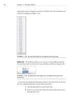
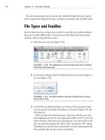
selecting this menu. Change the scale here, and Revit will scale annotations and
symbols accordingly (see Figure 1.34).
FIGURE 1.34 The scale menu allows you to change the scale of your view.
Detail Level
The detail level allows you to view your model at different qualities.
You have three levels to choose from: Coarse, Medium, and Fine (see Figure 1.35).
FIGURE 1.35 The detail level control allows you to set different view levels for the
current view.
If you want more graphical information with this view, select Fine. To see how
the view is adjusted using this control, follow these steps:
1. Click the detail level icon and choose Fine.
2. Zoom in on a wall corner. Notice the wall components are now
showing in the view.
The Revit Architecture Interface
25
TIP
When you change the view control in a view, it is not a temporary
display. You are telling Revit how you want to plot this view. The view you
see on the screen is the view you will see when it comes out of the plotter.
There are other items on the View Control bar, but we’ll discuss them when
they become applicable to the exercises.
The View Tab
Since Revit is one big happy model, you will quickly find that simply viewing the
model is quite important. Within Revit, you can take advantage of some function-
ality in the Navigation bar. To activate the Navigation bar, first go to the View tab,
then click the User Interface button. Make sure the Navigation bar is activated, as
shown in Figure 1.36.
One item we need to look at on the Navigation bar is the steering wheel.
FIGURE 1.36 The View tab allows you to turn on and off the Navigation bar.
The Steering Wheel
The steering wheel allows you to zoom, rewind, and pan. When you click the steer-
ing wheel icon, a larger control panel will appear in the view window. To choose one
of the options, you simply pick (left-click) one of the options, and hold the mouse
button as you execute the maneuver.
To use the steering wheel, follow along:
1. Pick the steering wheel icon from the Navigation bar, as shown in
Figure 1.37.
2. Once the steering wheel is in the view window (as illustrated in
Figure 1.37), left-click and hold Zoom. You can now zoom in and out.
Chapter 1 • The Revit World
26
FIGURE 1.37 You can use the steering wheel to navigate through a view.
3. Now click and hold Rewind in the steering wheel. You can now find
an older view, as shown in Figure 1.38.
FIGURE 1.38 Because Revit does not include zoom commands in the Undo
function, you can rewind to find previous views.
4. Do the same for Pan, which is also found on the outer ring of the
steering wheel. After you press and hold Pan, you can navigate to
other parts of the model.
Although you can do all of this with your wheel button, some users still prefer
the icon method of panning and zooming. For those of you who prefer the icons,
you will also want to use the icons for the traditional zooms as well.
Traditional Zooms
The next items on the Navigation bar are the good old zoom controls. The abili-
ties to zoom in, zoom out, and pan are all included in this function, as shown in
Figure 1.39.
Of course, if you have a mouse with a wheel, you can zoom and pan by either
holding down the wheel to pan or by wheeling the button to scroll in and out.
The Revit Architecture Interface
27
FIGURE 1.39 The standard zoom commands
Thin Lines
Back on the View tab, you will see an icon called Thin Lines, as shown in Figure 1.40.
Let’s talk about what this icon does.
In Revit Architecture, there is no such thing as layers. Line weights are con-
trolled by the actual objects they represent. In the view window, you see these line
weights. As mentioned before, what you see is what you get. Sometimes, however,
these line weights may be too thick for smaller-scale views. By clicking the Thin
Lines icon, as shown in Figure 1.40, you can force the view to display only the
thinnest lines possible to still see the objects.
FIGURE 1.40 Clicking the Thin Lines icon will allow you to “operate” on the finer items
in a model.
To practice using the Thin Lines function, follow along:
1. Pick the Thin Lines icon.
2. Zoom in on the upper-right corner of the building.
Chapter 1 • The Revit World
28
3. Pick the Thin Lines icon again. This toggles the mode back and forth.
4. Notice the lines are very heavy.
The line weight should concern you. As mentioned earlier, there is no such
thing as layers in Revit Architecture. This topic is addressed in Chapter 13.
3D View
The 3D View icon brings us to a new conversation. Complete the following steps
that will move us into the discussion on how a Revit model comes together!
1. Click the 3D View icon, as illustrated in Figure 1.41.
FIGURE 1.41 The 3D View icon will be heavily used.
2. On the View Control bar, click the Visual Style button and choose
Shaded with Edges, as illustrated in Figure 1.42.
FIGURE 1.42 The Visual Style button enables you to view your model in
color. This is typical for a 3D view.
3. Again on the View Control bar, select Shadows Off and turn the shad-
ows on, as illustrated in Figure 1.43, and again in Figure 1.45.
A word of caution:
if you do turn your
shadows on, do so
with care. This could
be the single worst
item in Revit in terms
of performance deg-
radation. Your model
will slow down with
shadows on.
The Revit Architecture Interface
29
FIGURE 1.43 Shadows create a nice effect, but at the expense of RAM.
Within the 3D view is the ViewCube. It is the cube in the upper-right corner of
the view window. You can switch to different perspectives of the model by clicking
on the quadrants of the cube (see Figure 1.44).
FIGURE 1.44 The ViewCube lets you freely look at different sides of the building.
TIP
The best way to navigate a 3D view is to press and hold the Shift
key on the keyboard. As you holding the Shift key, press and hold the wheel
on your mouse. Now move the mouse around. You will be able to dynami-
cally view the model (see Figure 1.45).
FIGURE 1.45 The 3D model with shading and shadows
Go back to the floor plan. Wait! How? This brings us to quite an important
topic in Revit: the Project Browser.
Chapter 1 • The Revit World
30
The Project Browser
Revit is the frontrunner of BIM. BIM is sweeping our industry for a reason. One of
the biggest reasons is the fact that you have a fully integrated model right in front
of you. What this means is that when you need to open a different floor plan, eleva-
tion, detail, drawing sheet, or 3D view, you can find it all right here in the model.
Also, this means our workflow is going to change. In most cases, it is going to
change drastically. When you think about all the external references and con-
voluted folder structures that comprise a typical job, you can start to relate it to
the way Revit uses the Project Browser. Within Revit, you are using the Project
Browser instead of the folder structure previously used in CAD.
This approach changes the playing field. The process of closing the file you are
in and opening the files you need to work on is restructured in Revit to enable
you to stay in the model. You never have to leave one file to open another. You
also never need to rely on external referencing to complete a set of drawings.
Revit and the Project Browser will put it all right in front of you.
To start using the Project Browser, follow along:
1. To the far left of the Revit dialog is the Project Browser (see
Figure 1.46).
FIGURE 1.46 The Project Browser is your new Windows Explorer.
2. The Project Browser is broken down into categories. One category is
Floor Plans. In the Floor Plans category, double-click on Level 1.
3. Next, double-click on Level 2. Notice that your display level is set to
Coarse. This is because any change you make on the View Control
bar is for that view only. When you went to Level 2 for the first time,
the change to the display level had not been made yet.
The Project Browser
31
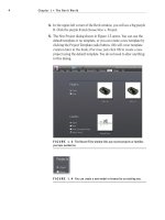
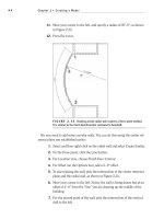
4. In the view window, you will see little icons that look like houses (see
Figure 1.47). These are elevation markers. The elevation marker to the
right might be in your building. If this is the case, you need to move it
out of the way.
FIGURE 1.47 Symbols for elevation markers in the plan. If you need to
move them, you must do so by picking a window. There are two actual items in
an elevation marker.
5. Pick a box around the elevation marker. When both the small triangle and
the small box are selected, move your mouse over the selected objects.
6. Your cursor will turn into a move icon. Pick a point on the screen and
move the elevation marker out of the way.
7. In the Project Browser, find the Elevations (Building Elevation) cat-
egory. Double-click on South.
8. Also in the Project Browser, notice there is a 3D Views category. Expand
the 3D Views category, and double-click on the {3D} choice. This will
bring you back to the 3D view you were looking at before this exercise.
WARNING
Hey! What happened to my elevation? You are in
Revit now. Items such as elevation markers, section markers, and callouts
are no longer just “dumb” blocks. They are linked to the actual view they are
calling out. If you delete one of these markers, you will delete the view asso-
ciated with it. If you and your design team have been working on that view,
then you lost that view. Also, you must move any item deliberately and with
caution. This elevation marker you moved has two parts. The little triangle
is actually the elevation. The little box is the part of the marker that records
the sheet number the elevation will wind up on. If you do not move both
items by placing a window around them, the elevation’s origin will remain in
its original position. When this happens, your elevation will look like a sec-
tion, and it will be hard to determine how the section occurred.
Chapter 1 • The Revit World
32
Now that you can navigate through the Project Browser, adding other compo-
nents to the model will be much easier. We can now begin to add some windows.
Windows
By clicking on all of these views, you are simply opening a view of the building,
not another file that is stored somewhere. For some users this can be confusing.
(It was for me.)
When you click around and open all these views, they stay open. You can
quickly open many views. There is a way to manage these views before they get
out of hand.
In the upper-right corner of the Revit dialog, you will see the traditional close
and minimize/maximize buttons for the application. Just below them are the
traditional buttons for the files that are open, as shown in Figure 1.48. Click
the X for the current view.
FIGURE 1.48 You can close a view by clicking the X for the view. This does not close
Revit, or an actual file for that matter — it simply closes that view.
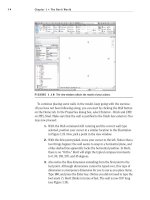
In this case, you have multiple views open. This situation (which is quite com-
mon) is best managed on the View tab. To utilize the Window menu, perform
the following steps:
1. On the Window panel of the View tab, click the Switch Windows but-
ton, as shown in Figure 1.49.
2. After the menu is expanded, look at the open views.
FIGURE 1.49 The Switch Windows menu lists all the current views that
are open.
The Project Browser
33
3. Go to the {3D} view by selecting it from the Window menu by click-
ing the 3D icon at the top of the screen or by going to the {3D} view
in the Project Browser.
4. On the Windows panel, click Close Hidden Windows.
5. In the Project Browser, open Level 1.
6. Go to the Windows panel and select Tile Windows.
7. With the windows tiled, you can see the Level 1 floor plan along with
the 3D view to the side. Select one of the walls in the Level 1 floor plan.
Notice it is now selected in the 3D view to the side. These views you
have open are mere representations of the model from that perspective.
Each view of the model can have its own independent view settings.
bu t i us e d t o ty p e My Co M M a n d s !
You can still type your commands. In the Revit menus, you may have noticed
that many items have a two- or three-letter abbreviation to the right. This is
the keyboard shortcut associated with the command. You can make your own
shortcuts or you can modify existing keyboard shortcuts — if you navigate
to the View tab. On the Windows panel, click the User Interface button. In
the drop-down menu, click the Keyboard Shortcuts button. Here you can
add or modify your keyboard shortcuts.