DISTRIBUTED AND PARALLEL SYSTEMSCLUSTER AND GRID COMPUTING 2005 phần 9 docx
Bạn đang xem bản rút gọn của tài liệu. Xem và tải ngay bản đầy đủ của tài liệu tại đây (473.91 KB, 23 trang )
172
DISTRIBUTED AND PARALLEL SYSTEMS
[Ramalingam and Reps, 1996] Ramalingam, G. and Reps, Thomas W. (1996). An incremental
algorithm for a generalization of the shortest-path problem. J. Algorithms, 21(2):267–305.
[Steen et al., 1999] Steen, M., Homburg, P., and Tannenbaum, A. S. (1999). Globe: A wide-
area distributed system. IEEE Concurrency.
[Tusch, 2003] Tusch, R. (2003). Towards an adaptive distributed multimedia streaming server
architecture based on service-oriented components. In Böszörményi, L. and Schojer, P., ed-
itors, Modular Programming Languages, JMLC 2003, LNCS 2789, pages 78–87. Springer.
[Tusch et al., 2004] Tusch, R., Böszörményi, L., Goldschmidt, B., Hellwagner, H., and Scho-
jer, P. (2004). Offensive and Defensive Adaptation in Distributed Multimedia Systems.
Computer Science and Information Systems (ComSIS), 1(1):49–77.
[Zanden, 1996] Zanden, B. Vander (1996). An incremental algorithm for satisfying hierar-
chies of multiway dataflow constraints. ACM Transactions on Programming Languages and
Systems, 18(1):30–72.
COMPONENT BASED FLIGHT SIMULATION IN
DIS SYSTEMS
Krzysztof Mieloszyk, Bogdan Wiszniewski
Faculty of Electronics, Telecommunications and Informatics
Gdansk University of Technology
,
Abstract
Distributed interactive simulation constitutes an interesting class of information
systems, which combine several areas of computer science enabling each in-
dividual simulation object to visualize dynamic states of all distributed objects
participating in the simulation. Objects are unpredictable and must exchange
state information in order to correctly visualize a dynamic 3D scene from their
local perspectives. In the paper, a component based approach developed in the
ongoing project at GUT
1
, has been described; it can reduce the volume of state
information being exchanged without losing messages essential for reliable ex-
ecution of simulation scenarios.
Keywords:
Distributed objects, remote state monitoring
Introduction
Distributed Interactive Simulation (DIS) systems form an important appli-
cation class of collaborative computing environments, in which many indepen-
dent and autonomous simulation objects, real objects and human operators are
connected to one computational framework. In may be for example a local
cluster of helicopter flight simulators in a lab with a group of real tanks oper-
ating in a remote shooting range, a city traffic simulation system where cars
and traffic lights are simulated but some intersections are operated by real po-
licemen, or a complex building on a simulated fire seen on computer screens
at the command center, and real firemen on a drill. Any such system performs
specific computations, which are unpredictable, have no algorithmic represen-
tation, and because of participating real objects, all events must be handled in
real-time despite of the system geographical distribution.
Objects participating in a simulation exercise are sending updates on their
local state to other objects in irregular intervals. If the updates were sent just
in periodic samples, a network supporting any realistic DIS system with many
object
s
would soon be overloaded. Moreover, increasing dynamics of reporting
174
DISTRIBUTED AND PARALLEL SYSTEMS
objects would imply higher sampling rate and would make the performance
problems even worse. Delayed (or lost) messages would certainly make any
visualization unrealistic. However, if a simulated object dynamics could be
estimated with some function of time, the number of messages to be sent would
be limited, since “new” states would be calculated by a receiving object instead
of sending them out by the reporting object.
This paper reports on the project started at TUG in 2002 and aimed at devel-
oping a DIS system with time-critical constraints, involving simulated flying
objects (helicopters) and ground vehicles (tanks) in a 3D space.
1.
DIS system architecture
Any DIS system consists of simulators (called simulation objects), each one
designed to model a specific human operated device or vehicle. Any partic-
ular simulator may be operating in a distinct geographical location, and its
underlying operating system, software and hardware are usually incompatible
to other simulators, preventing direct interaction between them. In order to
create a collaborative computing environment a system architecture must en-
able integration of such objects (called active participants), and also provide
access for observers (called passive participants) with logging and monitoring
capabilities. Active participants exchange information to update one another
on their states as soon as they change. State updates sent by reporting objects
are needed by receiving objects to model a 3D global dynamic virtual scene
from their local perspectives. Passive observers usually limit their actions to
on-line state tracing and logging for future replay, evaluation of active partic-
ipants progress in a particular training scenario, as well as collecting data for
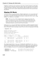
new training scenarios. A generic architecture of a DIS system is outlined in
Figure 1; it involves communication, service, and interaction layers, with dis-
tinct functionality and interfaces, marked with vertical arrows described further
on.
Figure 1. Distributed interactive system architecture
Component Based Flight Simulation in DIS Systems
175
Interaction layer. Human operator provides an external stimulus affecting
the internal state of a simulator. According to the semantics of the latter and its
current state a new state is determined, reported to the lower layer simulation
services, and broadcasted via the communication layer. State updates are re-
ceived at irregular intervals by simulation services of an interested participant
and passed to the visualizer component, which generates (modifies) its local
perspective of a global dynamic scene. Based on the view of moving objects
outside the cabin and a local state indicated by flight instruments inside the
cabin, a decision is made by the human operator (pilot) on the next stimulus
(maneuver).
Service layer. Simulation services provided by the service layer enable re-
duction of the volume of state update messages being sent over the system by
active participants. If the simulation object movement (state trajectory) can be
described with kinesthetic parameters like acceleration, speed, position, mass,
force, moment, etc., state prediction can be based on Newtonian rules of dy-
namics, using a technique known as dead reckoning [Lee2000]. States that can
be calculated based on the current reported state do not have to be sent out,
as the receiving participant can calculate them anyway. Further reduction of
the volume of state updates can be achieved by relevance filtering of messages
that are redundant with regard to some specific context of the scene, e.g. a
reporting object is far away and its movement will result in a pixel-size change
at a remote display.
Communication layer. The main job of the bottom layer shown in Figure 1
is to make the underlying network transparent to upper layers. Objects may
want to join and leave the simulation at any time, require reliable sending of
messages, and need time synchronization. This layer has no knowledge on the
semantics of data being sent by simulation objects but has knowledge about the
location of participants over the network. Two models of communication have
been implemented in the project reported in this paper: one with a dedicated
server and another with multicast [MKKK2003]. The former (server based)
enables lossless communication and make data filtering easier, but the cost is
that each message has to go through the server and a network load increases
when many participants work in the same local area network. The latter is
scalable, but requires implementation of dedicated transmission protocols on
top of the existing unreliable UDP protocol.
2.
Component interaction model
Since simulation objects have to invoke specialized services of the com-
munication layer, rather then to communicate directly with each other. The
communication layer must implement a standard, system-wide functionality.
176
DISTRIBUTED AND PARALLEL SYSTEMS
For example, High Level Architecture (HLA) standard [HLA] requires de-
livery of such services as: federation management for creating, connecting,
disconnecting and destroying simulation objects in the system, time manage-
ment for controlling logical time advance and time-stamping of messages, and
declaration management for data posting and subscribing by simulation ob-
jects.
Reduction of the volume of data being sent by objects is achieved by a dead
reckoning technique, which basically extrapolates new position of an object
using its previous position and state parameters such as velocity or accelera-
tion. If object movements are not too complex, the amount of messages to be
sent can be significantly reduced [Lee2000] However, the method developed
in the reported project utilizes a notion of a semantics driven approach to mes-
sage filtering, based on maneuver detection, allowing for further reduction of
the space of states to be reported. This has been made possible by introducing
operational limits characterizing real (physical) objects (vehicles) [OW2003].
We will refer to this method briefly when presenting below another important
concept introduced in the reported project, which is component based simula-
tion.
In order to build and run a simulation system, the reported project required
simulators of various physical objects of interest. They had to be realistic in the
sense of their physical models, but allowing for easy configuration and scala-
bility of simulated vehicles. This has been achieved by adopting the concept
of a physical component shown in Figure 2a.
A component has its local state set initially to some predefined value.
Upon the external stimulus coming from the operator or other component its
new (resultant) state is calculated as where G represents a
state trajectory of the simulated component, given explicitly by a state func-
tion or implicitly by a state equation. Subvector of the resultant state is
reported outside to other components (locally) or other simulators (externally),
where F is a filtering function, selecting state vector elements relevant to other
components or simulators.
With such a generic representation a component may range from the body
with a mass, airfoil objects, like a wing, rotor or propeller, through various
types of engines generating power and momentum, up to undercarriage inter-
acting with a ground.
Simulation object
The main idea behind the component based approach is to divide a sim-
ulated object into most significant units, and then to simulate each one sep-
arately. This approach allows for flexibility, since simulators can be readily
reconfigured by changing parameters of a particular component (or by replac-
Component Based Flight Simulation in DIS Systems
177
Figure 2. Simulation object: (a) generic component (b) view of components (c) remote view
ing one with another), as well as parallelization, since components may run on
clusters if more detailed calculations are required.
With the external stimulus, the user can influence behavior of the compo-
nent work by changing some of its parameters. Reported state vector
can affect the state of other components of the simulation object. Based on all
states, control parameters and the semantics of a component, it is possible to
calculate the external state vector as an influence of the component on simu-
lated object. After combining all state vectors reported by components of the
simulation object, it is possible to define its resultant behavior.
Consider for example two cooperating components, an engine and a pro-
peller. In order to simulate correctly each component, local state vectors
of an engine and a propeller have over 10 elements, and over 15 elements re-
spectively. However, interaction between them can be modeled with just a
2-element vector consisting of a rotation velocity and torque. Similarly, a two
element state vector is sufficient to represent cooperation between a helicopter
rotor and an engine, despite that simulation of a rotor requires over 25-element
state vectors.
The general modeling technique is to describe a simulation object with a
graph, of which each single node corresponds to the respective component.
For each pair of nodes which can affect one another an arc is drawn and the
corresponding reported state vector associated. The size of reported state
178
DISTRIBUTED AND PARALLEL SYSTEMS
vectors attributed to individual arcs determine the real volume of data that have
to be exchanged between components during simulation. For simulation ob-
jects considered in the project, namely ground vehicles, single and twin rotor
helicopters, propeller and jet planes, and which may consist of the components
described below the size of reported state vectors never exceeded two. A
sample view of cooperating components of a simulated single rotor helicopter
is shown in Figure 2b
Wing. A wing has parameters which describe its dimension, fixing point to
the fuselage and the airfoil sections with characteristics combining lift and drag
with angle of attack. State of the wing can be affected by the arrangement of
ailerons and flaps, and its possible rotation along the longitudinal axis. In this
way it is possible to model both lifting and control surfaces of the wing. Addi-
tionally, by taking into consideration linear speed of the air stream or angular
speed of the wing, the resultant moment and force applied to the simulated
object can also be calculated.
Rotor. A helicopter rotor is the most complex component in the project, as
it is modeled with several rotating wings (blades). Its state vector elements in-
clude dimension of blades, their number, elasticity, induced speed of air flow,
airfoil section characteristics, blade fluctuations and angular speed. By chang-
ing parameters affecting the collective pitch and periodic pitch, the user (pi-
lot) can control the rotor in the same way as in a real helicopter [SN2002].
Reported state vector consists of the resultant forces and moments cal-
culated at over a dozen points evenly distributed over a rotor disk. It is also
necessary to consider torque, which is required to determine correctly the state
of the entire power transmission system.
Propeller. This component is a simplified version of a helicopter rotor,
based on the same semantics and parameters. Elasticity and fluctuations of
blades are neglected in calculating of but the parameter describing the
collective pitch setting is added. The internal state vector of a propeller is the
same as in the rotor component.
Engine. This component supports the semantics of both, a jet turbine and
a piston engine. Including the internal state vector describing angular speed,
working temperature and the maximum power, the user can control its behavior
by setting up a throttle. Calculation of the reported state vector requires
gathering torque values of all attached components, like a propeller or rotor,
to calculate the resulting angular speed for the entire power transmission unit
taking into account its inertia.
Component Based Flight Simulation in DIS Systems
179
Undercarriage. It is the only component that allows the simulated object to
interact with a ground. The internal state vector describes the radius of a tire,
shock-absorber lead, and its elasticity, as well as speed of the entire plane, and
the relative location of the undercarriage with regard to the plane (helicopter)
body. This component has its semantics, defined by a characteristic describing
interaction patterns between the tire and the absorber during the contact with a
ground. By changing the angle of turn of the wheel and the braking factor, it
is possible to control the traction over the runway. As with other components,
the reported state vector describes the moment and the reaction force of
the ground applied through the undercarriage to the simulated object body.
Remot
e
object interaction
As mentioned before any simulation object in a DIS system sends out up-
dates on its state changes to enable other (remote) objects to calculate its po-
sition in global scene from the local perspective of each one. The volume of
messages is reduced by adopting a dead reckoning scheme, allowing calcu-
lation of some “future” states based on current states. While dead reckoning
applies mostly to calculating trajectories of moving objects, further reduction
of the volume of information being sent is possible based on specific relation-
ships between various elements of the material object state vector. A sample
view of a remote object’s state (a helicopter) from the local perspective of an-
other object (also a helicopter) is shown in Figure 2c
Active participants. State vector reported by each component locally
may allow a certain degree of redundancy, depending on the specific internal
details of the simulation object. However, the reported state (update) sent out
to remote objects must use a state vector in a standard form. In the current
implementation it consists of position orientation linear velocity linear
acceleration angular velocity angular acceleration resultant force
and resultant moment In a properly initiated simulation system, where
each receiver (observer) has once got full information about each participant,
for objects associated with decision events (maneuvers initiated by their human
operators) only changes in their acceleration are needed [OW2003].
Passive participants. State prediction is less critical for passive partici-
pants, as they do not interact (in the sense of providing a stimulus) with other
objects. They do not have any physical interpretation and there is no need to
inform users about their existence in a system. They may be independent 3D
observers, like a hot-air balloon, or a 2D radar screen, or a map with points
moving on it. Their only functionality is monitoring and/or logging the traffic
of state update messages. In a DIS system implemented in the project a logger
has been introduced. Based on the recorded log entries it can create simulation
180
DISTRIBUTED AND PARALLEL SYSTEMS
scenarios, which can be next edited, modified and replayed in the system. In
that particular case the logger may temporarily become an active participant.
Human operator
In order to implement any realistic DIS scenario involving “material” ob-
jects two problems must be solved. One is state predictability, important from
the point of view of the volume of state update messages, and another is object
ability to perform maneuvers within specific limits imposed by its operational
characteristics. Each object having a mass and characterized with kinesthetic
parameters behaves according to the Newtonian laws of dynamics. Classes
of behavior that such a material object may exhibit are described by basic
equations combining these parameters (function Such a form of ob-
ject representation, although true from the point of view of physics is far too
detailed from the point of view of simulating exercises with real flying objects
controlled by humans. It has been argued [OW2003] that by introducing the
notion of a maneuver and operational characteristics of simulation objects, the
space of possible states to be considered can be significantly reduced. In con-
sequence, there are less states to predict and the flow of state update messages
can be reduced further.
State predictability. The “logic” of flight may be described with a simple
automaton involving just five states representing human operator (pilot). The
basic state of a flying object is neutral, i.e. it remains still or is in a uniform
straight line motion. According to the first Newton’s law of dynamics both
linear and angular accelerations are zero, while the linear velocity is constant.
An object in a neutral state may start entering a new maneuver and keep doing
it as long as its linear or angular acceleration vary. This may eventually lead to
a stable state, which is the actual maneuver; in that case both linear and angular
acceleration vectors of the object are constant and at least one of them must be
non-zero. Any subsequent increase or decrease of any of these acceleration
vectors implies further entering or exiting a maneuver. Exiting a maneuver
may end up with entering another maneuver or returning to a neutral state.
There is also a crash state, when at least one of the object parameters exceeds
its allowed limits, e.g. exceeding a structural speed of the airplane ends-up with
its disintegration. It found out in the project, practically each state transition
of the automaton described above can be detected just by tracing changes of
angular or linear acceleration.
Operational characteristics. All components described before has realistic
operational limits, usually listed in the user’s manual of the simulated object.
The mass may vary, but stay between some minimum (empty) and maximum
(loaded) values. There are several speeds characterizing a flying object, e.g.
Component Based Flight Simulation in DIS Systems
181
for planes it is the minimum (stall) speed for each possible configuration (flaps
up or down, landing gear up or down), maximum maneuvering speed to use in
maneuvers or turbulent air, and maximum structural speed not to be exceeded
even in a still air. Resultant lift and drag forces for the wing are the function
of the airflow speed and angle of attack, which may change up to the critical
(stall) angle, specific to a given profile. Finally thrust is a function of engine
RPMs, which may change within a strictly defined range of [min,max] values.
Based on these parameters, and a maneuver “semantics” described before, it
is possible to calculate (predict) most of the in-flight states intended by the
human operator, excluding only random and drastic state changes such as mid-
air collision or self-inflicted explosion.
3.
Summary
In the current experimental DIS application three classes of simulation ob-
jects have been implemented using components described in the paper: a tank,
a light propeller airplane, and two kinds of helicopters, with single or twin ro-
tors. The notion of a generic component introduced in Figure 2a proved to be
very useful. Current development is aimed at expanding the concept of compo-
nents on vessels, which besides a propeller-like component and engine, require
a body model, simple enough to avoid complex computations but precise to de-
scribe interactions between the hull and surrounding water.
Notes
Funde
d
by the State Committee for Scientific Research (KBN) under grant T-11C-004-22
1
.
References
[SN2002] Seddon J. and Newman S. (2002). Basic Helicopter Aerodynamics Masterson Book
Services Ltd.
[HLA] DoD. High Level Architecture interface specification. IEEE P1516.1, Version 1.3.
.
[Lee2000] Lee B.S., Cai W., Tirner S.J., and Chen L. (2000). Adaptive dead reckoning algo-
rithms for distributed interactive simulation. I. J. of Simulation, 1(1-2):21–34.
[MKKK2003] Mieloszyk K., Kozlowski S., Kuklinski R., and Kwoska A. (2003). Architec-
tural design document of a distributed interactive simulation system KBN-DIS (in Polish).
Technica
l
Report 17, Faculty of ETI, GUT.
[OW2003] Orlowski T. and Wiszniewski B. (2003). Stepwise development of distributed inter-
active simulation systems. In Proc. Int. Conf. Parallel and Applied Mathematics, PPAM03,
LNCS, Springer Verlag, to appear.
This page intentionally left blank
VI
ALGORITHMS
This page intentionally left blank
MANAGEMENT OF COMMUNICATION
ENVIRONMENTS FOR MINIMALLY
SYNCHRONOUS PARALLEL ML
Frédéric Loulergue
Laboratory of Algorithms, Complexity and Logic, Créteil, France
Abstract
Minimally Synchronous Parallel ML is a functional parallel language whose
execution time can then be estimated and dead-locks and indeterminism are
avoided. Programs are written as usual ML programs but using a small set of
additional functions. Provided functions are used to access the parameters of the
parallel machine and to create and operate on a parallel data structure. It follows
the cost model of the Message Passing Machine model (MPM).
In the current implementation, the asynchrony is limited by a parameter
called the asynchrony depth. When processes reach this depth a global syn-
chronization occurs. This is necessary to avoid memory leak. In this paper we
propose another mechanism to avoid such synchronization barriers.
1.
Introduction
Bulk Synchronous Parallel (BSP) computing, and the Coarse-Grained Mul-
ticomputer model, CGM, which can be seen as a special case of the BSP model,
have been used for a large variety of domains [4], and are currently widely used
in the research on parallel algorithms. The main advantages of the BSP model
are: deadlocks avoidance, indeterminism can be either avoided or restricted to
very specific cases ; portability and performance predictability.
The global synchronizations of the BSP model make many practical MPI
[18] parallel programs hardly expressible using the BSPlib library. This is why
some authors proposed [16] the BSP without barrier and the Message Passing
Machine (MPM) model. We decided to investigate the semantics of a new
functional parallel language, without synchronization barriers, called Mini-
mally Synchronous Parallel ML (MSPML) [14]. As a first phase we aimed at
having (almost) the same source language and high level semantics (program-
mer’s view) than Bulk Synchronous Parallel ML [12], a functional language
for Bulk Synchronous Parallelism (in particular to be able to use with MSPML
186
DISTRIBUTED AND PARALLEL SYSTEMS
work done on proof of parallel BSML programs with the Coq proof assistant),
but with a different (and more efficient for unbalanced programs) low-level
semantics and implementation.
Due to the asynchronous nature of MSPML, storage of values, which may
be requested by processors in the future, is needed in communication environ-
ments. For a realistic implementation the size of these communications envi-
ronments should be of course bounded. This makes the emptying of the com-
munications environments necessary when they are full. This paper presents
two solutions for this problem.
We first present informally MSPML (section 2). Then (section 3) we give
the mechanism to empty the communication environments. We end with re-
lated work, conclusions and future work (sections 4 and 5).
2.
Minimally Synchronous Parallel ML
Bulk Synchronous Parallel (BSP) computing is a parallel programming
model introduced by Valiant [17] to offer a high degree of abstraction in the
same way as PRAM models and yet allow portable and predictable perfor-
mance on a wide variety of architectures. A BSP computer is a homogeneous
distributed memory machine with a global synchronization unit which executes
collective requests for a synchronization barrier.
The BSP execution model represents a parallel computation on processors
as an alternating sequence of computation super-steps and communications
super-steps with global synchronization. BSPWB, for BSP Without Barrier,
is a model directly inspired by the BSP model. It proposes to replace the
notion of super-step by the notion of m-step defined as: at each m-step, each
process performs a sequential computation phase then a communication phase.
During this communication phase the processes exchange the data they need
for the next m-step. The parallel machine in this model is characterized by
three parameters (expressed as multiples of the processors speed): the number
of processes the latency L of the network, the time which is taken to one
word to be exchanged between two processes. This model could be applied to
MSPML but it will be not accurate enough because the bounds used in the cost
model are too coarse.
A better bound is given by the Message Passing Machine (MPM) model
[16]. The parameters of the Message Passing Machine are the same than those
of the BSPWB model but the MPM model takes into account that a process
only synchronizes with each of its incoming partners and is therefore more
accurate (the cost model is omitted here). The MPM model is used as the exe-
cution and cost model for our Minimally Synchronous Parallel ML language.
There is no implementation of a full Minimally Synchronous Parallel ML
(MSPML) language but rather a partial implementation as a library for the
Management of Communication Environments for MSPML
187
functional programming language Objective Caml [11]. The so-called MSPML
library is based on the following elements:
It gives access to the parameters of the underling architecture which is con-
sidered as a Message Passing Machine (MPM). In particular, it offers the func-
tion
p
such that the value of
p
() is the static number of processes of the
paralle
l
machine. The value of this variable does not change during execution.
There is also an abstract polymorphic type par which represents the type of
parallel vectors of objects of type one per process. The nesting of
par types is prohibited. This can be ensured by a type system [5].
Th
e
parallel constructs of MSPML operate on parallel vectors. A MSPML
program can be seen as a sequential program on this parallel data structure and
is thus very different from the SPMD paradigm (of course the implementa-
tion of the library is done in SPMD style). Those parallel vectors are created
by mkpar, so that (mkpar f) stores (f i) on process
for between 0 and
We usually write fun pid
e for f to show that the expression e may
be different on each process. This expression e is said to be local. The ex-
pression (mkpar f) is a parallel object and it is said to be global. For example
the expression mkpar(fun pid pid) will be evaluated to the parallel vector
In the MPM model, an algorithm is expressed as a combination of asyn-
chronous local computations and phases of communication. Asynchronous
phases are programmed with mkpar and with apply.
It is such as apply (mkpar f)
(
mkpar e) stores (f i) (e i) on process
The communication phases are expressed by get and mget. The semantics
of get is given by the following equation where % is the modulo:
The mget function is a generalization which allows to request data from
several processes during the same m-step and to deliver different messages to
different processes. It is omitted here for the sake of conciseness (as well as
the global conditional).
A MSPML program is correct only if each process performs the same over-
all number of m-steps, thus the same number of calls to get (or mget). Incorrect
programs could be written when nested parallelism is used. This is why it is
currently forbidden (a type system can enforce this restriction [5]).
Som
e
useful functions can be defined using the primitives. This set of func-
tions constitutes the standard MSPML library (). For ex-
ample, the direct broadcast function which realizes a broadcast can be written:
188
DISTRIBUTED AND PARALLEL SYSTEMS
Th
e
semantics of bcast is: bcast
3.
Management of Communication Environments
To explain how the communication environments could be emptied, the low-
level semantics of MSPML should be presented.
During the execution of and MSPML program, at each process the system
has a variable containing the number of the current m-step. Each time
the expression get vv vi is evaluated, at a given process
is increased by one.
the value this process holds in parallel vector vv is stored together with
the value of in the communication environment. A communica-
tion environment can be seen as an association list which relates m-step
numbers with values.
the value this process holds in parallel vector vi is the process number
from which the process wants to receive a value. Thus process sends
a request to process it asks for the value at m-step When
process receives the request (threads are dedicated to handle requests,
so the work of process is not interrupted by the request), there are two
cases:
1
2
3
it means that process has already reached
the same m-step than process Thus process looks in its commu-
nication environment for the value associated with m-step
and sends it to process
nothing can be done until process reaches
the same m-step than process
If the step 2 is of course not performed.
In a real implementation of MSPML, the size of the communication envi-
ronment is of course limited. It is necessary to provide the runtime system a
parameter called the asynchrony depth. This value, called mstepmax, is the
size of the communication environment in terms of number of values it can
store (number of m-steps). The implementation of communication environ-
ments are arrays com_env of size mstepmax, each element of the array being
a kind of pointer to the serialized value stored at the m-step whose number is
the array index.
A problem arises when the communication environments are full. When
the array at one process is filled then the process must wait because it cannot
proceed the next m-step. When all the communication environments are full, a
global synchronization occurs and the arrays are emptied. The m-step counter
is also reset to its initial value.
Management of Communication Environments for MSPML
189
The advantage of this method is its simplicity. Nevertheless it could be in-
efficient in terms of memory but also in terms of execution time since a global
synchronization is needed. Note that it is not only due to the communication
cost of the synchronization barrier which is (please see defini-
tions in section 2) for each process but also to the fact that a globally balanced
program but always locally imbalanced (which means that the communication
steps never occur at the same time) could lose a lot of efficiency. Thus another
mechanism could be proposed.
In order to avoid the waste of memory, each process should free the use-
less values stored in its communication environment. These useless values are
those whose associated m-step (the index in the array) is lower than the m-step
counter of each process, or to say it differently lower than the smallest m-step
counter.
Of course this information cannot be updated at each m-step without per-
forming a global synchronization, but it can be updated when a communication
occur between two processes. These processes could exchange their knowl-
edge of the current state of the other processes. To do so, each process has
in addition to its com_env array of size mstepmax and to its m-step counter
mstep: a value mstepmin
,
the smallest known m-step counter.
The com_env array is now a kind of queue. If mstep – mstepmin
mstepmax then there is still enough room to add a value in the communi-
cation environment at index mstep%mstepmax. The problem now is to
update the value mstepmin
.
This can be done using an array msteps of size the last known m-step
counters, the value of msteps at index
at process being unused (if used it
should be the value mstep). Without changing the data exchanged for per-
forming a
get
, each time a process requests a value from a process it sends
its mstep value. This value is put in the array msteps of process at index
When the process answers, knows that has at least reached the same
m-step as itself and it can update its array msteps at index
The new value of mstepmin, which is the minimum of the values of the ar-
ray msteps, could be computed only when needed, ie when the array com_env
is full, or could be computed each time a value is changed in the array msteps.
In the former case there may be a waste of memory, but in the latter case there
is a small overhead for the computation of the new value.
As an example we could have a MSPML program in which we evaluate
(bcast 0 vec) on a 3-processors machine. At the beginning each processor has
the following msteps array: (here we use at process the value
at index After the first get is done, the msteps arrays are:
190
DISTRIBUTED AND PARALLEL SYSTEMS
In fact, at the first m-step, process 0 has no communication request to do,
so it may reach the m-step number 1 before the communications are done with
the two other processes. So at process 0, the msteps array is more likely to be:
In both cases the first cell of the com_env array at process 0 could
be freed.
To increase the updating of the mstepmin value, we can change the data
exchanged during a get. When a process
answers to a request from a process
it could send the answer plus its mstep value to process which updates its
array msteps at index
In the previous example, assuming process 0 reached m-step number 1 be-
fore the communications are done with the two other processes, we would
have:
It is also possible to exchange a subpart of the arrays msteps during a get
to improve the updating of mstepmin. To do so we can keep a fixed number
of process identifiers for which the information has the most recently been
updated. In the previous example, assuming we keep only one identifier of
the most recently updated process and that the request from process 1 arrives
at process 0 before the request from process 2 we would have msteps[1] = 0
at process 2. With this solution the first cell of the com_env environment at
process 2 could be freed also after the first m-step.
Unfortunately these various protocols have a flaw: if one processor does not
communicate at all with the remaining of the parallel machine, its mstepmin
value will never be updated and this process will be blocked as soon as its
communication environment will be full. The solution to avoid deadlock is that
each time a process is blocked because of a full communication environment,
then it will request, after some delay, the value of mstep from one or several
other processes. This could be from only one processor at random, or from all
the processes. The former case decrease the chance to obtain a new value for
mstepmin but the latter is of course more costly.
We performed some experiments corresponding to the various versions pre-
sented in the examples [13]. Even when a reasonable subpart of msteps is
exchanged, the overhead is very small. Thus usually this would be more in-
teresting to use this protocol than to empty the communication environments
after a global synchronization barrier.
4.
Comparison to Related Work
Caml-flight, a functional parallel language [3], relies on the wave mecha-
nism. A sync primitive is used to indicated which processes could exchange
messages using a get primitive which is very different from ours: this primitive
asks the remote evaluation of an expression given as argument. This mecha-
Management of Communication Environments for MSPML
191
nism is more complex than ours and there is no pure functional high level se-
mantics for Caml-flight, Moreover Caml-flight programs are SPMD programs
which are more difficult to write and read. The environments used could store
values at each step. An asynchrony depth is also used in Caml-Flight but
it should usually be much smaller than in MSPML.
There are several works on extension of the BSPlib library or libraries to
avoid synchronization barrier (for example [10]) which rely on different kind
of messages counting. To our knowledge the only extension to the BSPlib stan-
dard which offers zero-cost synchronization barriers and which is available for
downloading is the PUB library [2]. The bsp_oblsync function takes as ar-
gument the number of messages which should be received before the super-
step could end. This is of course less expensive than a synchronization barrier
but it is also less flexible (the number of messages have to be known). With
this oblivious synchronization, two processes could be at different super-steps.
Two kind of communications are possible: to send a value (either in message-
passing style or in direct remote memory access, or DRMA, style) or to request
a value (in DRMA style). In the former case, the process which done more
super-steps could send a value (using bsp_put or bsp_send) to the other pro-
cess. This message is then stored in a queue at the destination. In the latter case
the PUB documentation indicates that a bsp_get produces “a communication”
both at the process which requests the value and the process which receives
the request. Thus it is impossible in this case that the two processes are not
in the same super-step. MSPML being a functional language, this kind of put-
like communication is not possible. But the get communication of MSPML is
more flexible than PUB’s one.
The careful management of memory is also very important in distributed
languages where references to remote values or objects can exist. There are
many distributed garbage collection techniques [9, 15]. They could be hardly
compared to our mechanism since there are no such references in MSPML. The
management of the communication environments is completely independent
from the (local) garbage collection of Objective Caml: the values put by a
ge
t
operation are copied in the communication environments making safe the
collection, at any time, of these values by the GC.
5.
Conclusions and Future Work
There are several ways to manage the communication environments of Min-
imally Synchronous Parallel ML. In most cases a small additional exchange of
information during each communication provide the best overall solution, both
in term of memory usage and time.
We will prove the correctness of the presented mechanism using Abstract
State Machines [7] by modeling the get operation with communicating evolv-
192
DISTRIBUTED AND PARALLEL SYSTEMS
ing algebras [6]. The properties will be expressed using First Order Timed
Logic [1] and the verification will be automated using model checking tools.
We also will perform more experiments, especially with applications rather
than examples. In particular we will further investigate the implementation
of the Diffusion algorithmic skeleton [8, 14] using MSPML and applications
implemente
d
using this algorithmic skeleton.
References
D. Beauquier and A. Slissenko. A first order logic for specification of timed algorithms:
basic properties and a decidable class. Annals of Pure and Applied Logic, 113, 2002.
O. Bonorden, B. Juurlink, I. von Otte, and O. Rieping. The Paderborn University BSP
(PUB) library. Parallel Computing, 29(2): 187–207, 2003.
E. Chailloux and C. Foisy. A Portable Implementation for Objective Caml Flight. Parallel
Processing Letters, 13(3):425–436, 2003.
F. Dehne. Special issue on coarse-grained parallel algorithms. Algorithmica, 14, 1999.
F. Gava and F. Loulergue. A Polymorphic Type System for Bulk Synchronous Parallel
ML
.
In PaCT 2003, number 2763 in LNCS, pp. 215–229. Springer, 2003.
P. Glavan and D. Rosenzweig. Communicating Evolving Algebras. In Computer Science
Logic, number 702 in LNCS, pp. 182–215. Springer, 1993.
Y. Gurevich. Evolving Algebras 1993: Lipari Guide. In Specification and Validation Meth-
ods, pp. 9–36. Oxford University Press, 1995.
Z. Hu, H. Iwasaki, and M. Takeichi. An accumulative parallel skeleton for all. In European
Symposium on Programming, number 2305 in LNCS, pp. 83–97. Springer, 2002.
R. Jones. Garbage Collection: algorithms for automatic dynamic memory management.
Wiley, 1999.
Jin-Soo Kim, Soonhoi Ha, and Chu Shik Jhon. Relaxed barrier synchronization for the
BSP model of computation on message-passing architectures. Information Processing
Letters, 66(5):247–253, 1998.
Xavier Leroy. The Objective Caml System 3.07, 2003. web pp. at www.ocaml.org.
F. Loulergue. Implementation of a Functional Bulk Synchronous Parallel Programming
Library. In
14
th IASTED PDCS Conference, pp. 452–457. ACTA Press, 2002.
F. Loulergue. Management of Communication Environments for Minimally Synchronous
Parallel ML. Technical Report 2004-06, University of Paris 12, LACL, 2004.
F. Loulergue, F. Gava, M. Arapinis, and F. Dabrowski. Semantics and Implementation of
Minimall
y
Synchronous Parallel ML. International Journal of Computer & Information
Science, 2004. to appear.
David Plainfossé and Marc Shapiro. A survey of distributed garbage collection techniques.
In Proc. Int. Workshop on Memory Management, 1995.
J. L. Roda, C. Rodríguez, D. G. Morales, and F. Almeida. Predicting the execution time of
message passing models. Concurrency: Practice and Experience, 11(9):461–477, 1999.
D. B. Skillicorn, J. M. D. Hill, and W. F. McColl. Questions and Answers about BSP.
Scientific Programming, 6(3):249–274, 1997.
M
.
Snir andW. Gropp. MPI the Complete Reference. MIT Press, 1998.
[1]
[2]
[3]
[4]
[5]
[6]
[7]
[8]
[9]
[10]
[11]
[12]
[13]
[14]
[15]
[16]
[17]
[18]
ANALYSIS OF THE MULTI-PHASE COPYING
GARBAGE COLLECTION ALGORITHM
Norbert Podhorszki
MTA SZTAKI
H-1518 Budapest, P.O.Box 63
Abstract The multi-phase copying garbage collection was designed to avoid the need for
large amount of reserved memory usually required for the copying types of
garbage collection algorithms. The collection is performed in multiple phases
using the available free memory. The number of phases depends on the size of
the reserved memory and the ratio of the garbage and accessible objects.
Keywords:
Garbage collection, logic programming.
Introduction
In the execution of logic programming languages, a logic variable can have
only one value during its existence, after its instantiation it cannot be changed.
Therefore, new values cannot be stored in the same memory area. Thus, the
memory consumption speed is very high and much smaller problems can be
solved with declarative languages than with procedural ones. Garbage collec-
tion is a very important procedure in logic programming systems to look for
memory cells that are allocated but not used (referenced) any more. Since the
late 50’s many garbage collection algorithms have been proposed, see classifi-
cations of them in [1][6]. The classical copying garbage collection [2] method
provides a very fast one-phase collection algorithm but its main disadvantage is
that the half of the memory is reserved for the algorithm. During the execution
of an application, in every moment, the number of all accessible objects on a
processing element must be less than the available memory for storing them.
Otherwise, the system fails whether garbage collector is implemented or not.
If the classical copying collector allocates the half of the memory for own use,
applications may not be executed. To decrease the size of the reserved area, a
multi-phase copying garbage collection (MC-GC) algorithm was presented in
[4]. It has been implemented in LOGFLOW [3], a fine-grained dataflow sys-
tem for executing Prolog programs on distributed systems. In this paper, the
194
DISTRIBUTED AND PARALLEL SYSTEMS
MC-GC algorithm is analysed giving its cost and the number of phases as a
function of the size of the reserved area and the ratio of garbage and accessible
memory areas. A short description of the multi-phase copying garbage collec-
tion algorithm can be found in Section 1. The costs and the number of phases
of the algorithm is analysed in Section 2.
1.
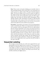
Multi-Phase Copying Garbage Collection Algorithm
The MC-GC algorithm splits the memory area to be collected into two parts,
the Copy and the Counting area, see Figure 1. The size of the Copy area
is chosen as large as possible but ensuring that all accessible objects can be
moved into the available Free area. The Free area is the reserved memory area
at the beginning and by not knowing the number of accessible objects in the
memory, the size of the Copy area equals to the size of the Free area. In the
first phase, see Figure 2, when traversing the references, objects stored in the
Copy area are moved to the Free area, while objects in the Counting area are
just marked (counted). At the end of the phase, the moved objects are moved
to their final place at the beginning of the memory (the references are already
set to this final place at the traversal).
Figure 1. MC-GC algorithm, starting
In the forthcoming phases, see Figure 3, the Counting area of the previous
phase should be collected. Knowing now the number of objects in this area,
the Copy area can be chosen larger than the available Free memory (which
has become also larger because garbage occupying the previous Copy area are
freed now). In other aspects, the algorithm is the same in all phases. The
algorithm repeats the phases until the whole memory is collected.
The main advantage of MC-GC is the efficiency: it provides a sufficiently
fast collector, all garbage is thrown away and a continuous memory can be used
by the application without the overhead of any special memory management.