Introduction to AutoCAD 2008 2D and 3D Design phần 7 pdf
Bạn đang xem bản rút gọn của tài liệu. Xem và tải ngay bản đầy đủ của tài liệu tại đây (7.09 MB, 38 trang )
216 Introduction to AutoCAD 2008
Fig. 13.41 Exercise 3
Fig. 13.42 Exercise 3 – the
Presspull tool from the 3D
Make control panel
45
104
182
2
45
12
78
R150
R68
R90
Fig. 13.43 Exercise 4 – outline
drawing
Fig. 13.44 Exercise 4
Ch13-H8512.qxd 4/4/07 6:50 PM Page 216
Introducing 3D modelling 217
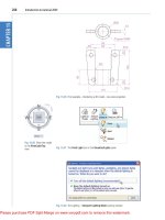
5. Fig. 13.45 shows the outline from which a solid of revolution can be
constructed. Using the Revolve tool construct the solid of revolution.
25
3.5
0.5
0.5
0.5
0.5
1.5
4
Axis of revolution
Scale: 10:1 Pline for Revolve of Nozzle
Fig. 13.45 Exercise 5
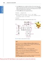
6. Construct the 3D solid model of a bracket, working to the informa-
tion given in Fig. 13.46.
R15
Holes ∅8
R15
15
6
42
R15
80
80
12
60
6
50
30
6
150
135
Tapped M6
Fig. 13.46 Exercise 6
7. Working to the dimensions given in Fig. 13.47, construct an extrusion
of the plate to a height of 5 units.
160
80
250
110
R50
Fig. 13.47 Exercise 7
Ch13-H8512.qxd 4/4/07 6:50 PM Page 217
218 Introduction to AutoCAD 2008
Fig. 13.48 Exercise 8
Profile outline Path
10
50
R15
155 155
15
15
Fig. 13.49 Exercise 9 – profile and
path dimensions
Fig. 13.50 Exercise 9
8.Working to the details given in the orthographic projection in Fig. 13.48,
construct a 3D model of the assembly.
After constructing the pline outline(s) required for the solid(s) of
revolution, use the Revolve tool to form the 3D solid.
9. Working to the polylines shown in Fig. 13.49, construct the Sweep
shown in Fig. 13.50.
Ch13-H8512.qxd 4/4/07 6:50 PM Page 218
Introducing 3D modelling 219
Fig. 13.51 The cross sections for
Exercise 10
Fig. 13.52 Exercise 10
10. Construct the cross sections as shown in Fig. 13.51, working to suit-
able dimensions. From the cross sections construct the lofts shown in
Fig. 13.52. The lofts are topped with a sphere constructed using the
Sphere tool.
Ch13-H8512.qxd 4/4/07 6:50 PM Page 219
CHAPTER 14
3D models in viewports
Aim of this chapter
To give examples of 3D solid models constructed in multiple viewport
settings.
Setting up viewport systems
One of the better methods of constructing 3D models is in different
viewport settings. This allows what is being constructed to be seen from
a variety of viewing positions. To set up a new viewport system:
1. Click View in the menu bar and from the drop-down menu which
appears click Viewports and in the sub-menu which then appears
click New Viewports (Fig. 14.1). The Viewports dialog appears
(Fig. 14.2).
Fig. 14.1 Selecting New
Viewports from the View
drop-down menu
220
Ch14-H8512.qxd 4/4/07 6:52 PM Page 220
3D models in viewports 221
2. Click the New Viewports tab and a number of named viewports
systems appears in the Standard Viewports list in the dialog.
3. Click the name Four: Equal, followed by a click on 3D in the Setup
popup list. A preview of the Four: Equal viewports screen appears
showing the views appearing in each of the four viewports.
4. Click the OK button of the dialog and the AutoCAD 2008 drawing
area appears showing the four viewport layout (Fig. 14.3).
Fig. 14.2 The Viewports dialog
Fig. 14.3 The Four: Equal
viewports layout
Ch14-H8512.qxd 4/4/07 6:52 PM Page 221
222 Introduction to AutoCAD 2008
First example – Four: Equal viewports (Fig. 14.7)
Fig. 14.4 shows a first angle orthographic projection of a support. To
construct a Scale 1:1 3D model of the support in a Four: Equal viewport
setting:
1. Click View in the menu bar, followed by a click on Viewports in the
drop-down menu, followed by another click on New Viewports in
the Viewports sub-menu. Make sure the 3D option is selected from the
Setup popup list and click the OK button of the dialog. The AutoCAD
2008 drawing area appears in a Four: Equal viewport setting.
Fig. 14.4 Orthographic projection
of the support for the first
example
2. Click in each viewport in turn, making the selected viewport active,
and Zoom to 1.
3. Set ISOLINES to 4.
4. Using the Polyline tool, construct the outline of the plan view of the
plate of the support, including the holes (Fig. 14.5). Note the views in
the other viewports.
5. Call the Extrude tool from the Solids toolbar and extrude the plan
outline and the circles to a height of 20.
6. With the Subtract tool from the Solids Editing toolbar, subtract the
holes from the plate (Fig. 14.6).
7. Call the Box tool and in the centre of the plate construct a box of
Widthϭ60, Lengthϭ60 and Heightϭ30.
8. Call the Cylinder tool and in the centre of the box construct a cylin-
der of Radiusϭ20 and Heightϭ30.
9. Call Subtract and subtract the cylinder from the box.
Ch14-H8512.qxd 4/4/07 6:53 PM Page 222
3D models in viewports 223
10. Click in the Right viewport and with the Move tool, move the box
and its hole into the correct position with regard to the plate.
11. With Union, form a union of the plate and box.
12. Click in the Front viewport and construct a triangle for one of the
webs attached between the plate and the box. With Extrude, extrude
Fig. 14.5 The plan view drawn
Fig. 14.6 The four views
after using the Extrude and
Subtract tools
Ch14-H8512.qxd 4/4/07 6:53 PM Page 223
224 Introduction to AutoCAD 2008
the triangle to a height of 10. With the Mirror tool, mirror the web to
the other side of the box.
13. Click in the Right viewport and with the Move tool, move the two
webs into their correct positions between the box and the plate. Then,
with Union, form a union between the webs and the 3D model.
14. While in the Right viewport, construct the other two webs and in
the Front viewport, move, mirror and union the webs as in steps 12
and 13.
Fig. 14.7 shows the resulting four-viewport scene.
Fig. 14.7 First example – Four:
Equal viewports
Second example – Four: Left viewports (Fig. 14.9)
1. Open the Four: Left viewport layout from the Viewports dialog.
2. Make a new layer of colour Magenta and make that layer current.
3. In the Top viewport construct an outline of the web of the Support
Bracket shown in Fig. 14.8. With the Extrude tool, extrude the parts
of the web to a height of 20.
4. With the Subtract tool, subtract the holes from the web.
5. In the Top viewport, construct two cylinders central to the extru-
sion, one of radius 50 and height 30, the second of radius 40 and
height 30. With the Subtract tool, subtract the smaller cylinder
from the larger.
6. Click in the Front viewport and move the cylinders vertically by 5
units. With Union form a union between the cylinders and the web.
Ch14-H8512.qxd 4/4/07 6:53 PM Page 224
3D models in viewports 225
7. Make the Front viewport active and at one end of the union, con-
struct two cylinders, the first of radius 10 and height 80, the second of
radius 15 and height 80. Subtract the smaller from the larger.
8. With the Mirror tool, mirror the cylinders to the other end of the
union.
9. Make the Top viewport current and with the Move tool, move the
cylinders to their correct positions at the ends of the union. Form a
union between all parts on screen.
10. Make the SE Isometric viewport current. From the Visual Styles
control panel popup list select Conceptual.
Fig. 14.9 shows the result.
Dimensions in millimetres
Name:
Scale:
A. Reader
1:1
Date:
Support Bracket 3/A
Title:
12/09/2006
DO NOT SCALE
Holes Ø80
Holes Ø20
R50
R5
R15
10
10
R60
30
20
300
80
60
Fig. 14.8 Working drawing for the
second example
Fig. 14.9 Second example – Four:
Left viewports
Ch14-H8512.qxd 4/4/07 6:53 PM Page 225
Third example – Three: Right viewports (Fig. 14.11)
1. Open the Three: Right viewport layout from the Viewports dialog.
Make sure 3D setup is chosen.
2. Make a new layer of colour Green and make that layer current.
3. In the Front viewport (top left-hand), construct a pline outline to the
dimensions in Fig. 14.10.
226 Introduction to AutoCAD 2008
Chamfer 20 × 20
25
30
5
340
35
65
20
100
55
5
Fig. 14.10 Third example – outline
for solid of revolution
4. Call the Revolve tool from the 3D Make control panel and revolve the
outline through 360Њ.
5. Make the SE Isometric viewport current. In the Visual Styles control
panel select Conceptual from its popup list.
The result is shown in Fig. 14.11.
Fig. 14.11 Third example –
Three: Right viewports
Ch14-H8512.qxd 4/4/07 6:53 PM Page 226
3D models in viewports 227
Notes
1. When working in viewport layouts such as in the above three examples,
it is important to make good use of the Zoom tool, mainly because
the viewports are smaller than the single viewport when working in
AutoCAD 2008.
2. As in all other forms of constructing drawings in AutoCAD 2008 fre-
quent toggling of SNAP, ORTHO and GRID will allow speedier and
more accurate working.
Revision notes
1. Outlines suitable for use when constructing 3D models can be con-
structed using the 2D tools such as Line, Arc, Circle and Polyline.
Such outlines must be changed either to closed polylines or to regions
before being incorporated in 3D models.
2. The use of multiple viewports can be of value when constructing 3D
models in that various views of the model appear enabling the operator
to check the accuracy of the 3D appearance throughout the construc-
tion period.
Exercises
1. Using the Cylinder, Box, Sphere, Wedge and Fillet tools, together
with the Union and Subtract tools and working to any sizes thought
suitable, construct the ‘head’ as shown in the Three: Right viewport in
Fig. 14.12.
Fig. 14.12 Exercise 1
Ch14-H8512.qxd 4/4/07 6:53 PM Page 227
228 Introduction to AutoCAD 2008
2. Using the tools Sphere, Box, Union and Subtract and working to the
dimensions given in Fig. 14.14, construct the 3D solid model as shown
in the isometric drawing in Fig. 14.13.
Fig. 14.13 Exercise 2
Sphere ∅140
Semi-sphere R50
Hole 55
× ∅30
∅40
70
∅50
55
48
Fig. 14.14 Exercise 2 – working
drawing
3. Each link of the chain shown in Fig. 14.15 has been constructed using
the Extrude tool, extruding a small circle along an elliptical path.
Copies of the link were then made, half of which were rotated in a
Right view and then moved into their positions relative to the other
links. Working to suitable sizes, construct a link and from the link con-
struct the chain as shown.
Fig. 14.15 Exercise 3
4. A two-view orthographic projection of a rotatable lever from a
machine is given in Fig. 14.16, together with an isometric drawing
Ch14-H8512.qxd 4/4/07 6:53 PM Page 228
3D models in viewports 229
of the 3D model constructed to the details given in the drawing in
Fig. 14.17. Construct the 3D model drawing in a Four: Equal view-
port setting.
R50
R8
R10
750
80 × 10
350
∅60
95 × ∅20
10
40
10
15
Fig. 14.16 Exercise 4 –
orthographic projection
Fig.14.17 Exercise 4
5. Working in a Three: Left viewport setting, construct a 3D model of
the faceplate to the dimensions given in Fig. 14.18. With the Mirror
tool, mirror the model to obtain an opposite facing model. In the
Isometric viewport call the Hide tool (Fig. 14.19).
Ch14-H8512.qxd 4/4/07 6:53 PM Page 229
230 Introduction to AutoCAD 2008
Fig. 14.19 Exercise 5
Dimensions in millimetres
M.Y.Name Scale 1:1 27/05/2006 FACE PLATE 7/FC
1123
∅105
∅60
∅150
∅180
Hole ∅40
R4
Holes SQ 9
Keyway 9 × 9
Fig. 14.18 Exercise 5 – dimensions
Ch14-H8512.qxd 4/4/07 6:53 PM Page 230
231
CHAPTER 15
The modification of 3D models
Aims of this chapter
1. To demonstrate how 3D models can be saved as blocks for insertion
into other drawings via the DesignCenter.
2. To show how a library of 3D models in the form of blocks can be con-
structed to enable the models to be inserted into other drawings.
3. To give examples of the use of the tools from the Operations sub-
menu from the Modify drop-down menu:
3D Array – Rectangular and Polar 3D arrays
Mirror 3D
Rotate 3D.
4. To give examples of the use of the Section Plane tool from the 3D
Make control panel.
5. To give examples of the use of the Helix tool.
6. To give a further example of construction involving the DYN method.
7. To show how to obtain different views of 3D models in 3D space
using:
Views from the 3D Navigate drop-down menu
Viewpoint Presets.
Creating 3D model libraries
In the same way as 2D drawings of parts such as electronics symbols,
engineering parts, building symbols and the like can be saved in a file as
blocks and then opened into another drawing by dragging the appropriate
block drawing from the DesignCenter, so can 3D models.
First example – inserting 3D blocks (Fig. 15.4)
1. Construct individual 3D models of the parts for a lathe milling wheel
holder to details as given in Fig. 15.1 on layers of different colours.
2. Save each of the 3D models of the parts to file names as given in Fig.
15.1 as blocks using the Make Block tool from the 2D Draw control
panel. When all seven blocks have been saved, the drawings on screen
can be deleted. Save the drawing with its blocks to a suitable file
name. In this example this is Fig01.dwg.
3. Set up a Four: Equal viewports setting.
Ch15-H8512.qxd 4/4/07 6:54 PM Page 231
232 Introduction to AutoCAD 2008
4. Open the DesignCenter with a click on its icon in the Standard
toolbar (Fig. 15.2), or by pressing the Ctrl and 2 keys of the keyboard.
5. In the DesignCenter click the directory Chapter 15, followed by
another click on Fig01.dwg and yet another click on Blocks. The saved
blocks appear as icons in the right-hand area of the DesignCenter.
6. Drag and drop the blocks one by one into one of the viewports on
screen. Fig. 15.3 shows the Nut block ready to be dragged into posi-
tion in the Right viewport. As the blocks are dropped on screen, they
will need moving into their correct positions in relation to other parts
of the assembly by using the Move tool from the 2D Draw control
panel in suitable viewports.
7. Using the Move tool, move the individual 3D models into their final
places on screen and render the Southeast Isometric viewport. Shade
using Visual Styles/Conceptual shading (Fig. 15.4).
Notes
1. It does not matter which of the four viewports any one of the blocks is
dragged and dropped into – the part automatically assumes the view of
the viewport.
2. If a block destined for layer 0 is dragged and dropped into the layer
Centre (which in our acadiso.dwt is of colour red and linetype CEN-
TER2), the block will take on the colour (red) and linetype of that
layer (CENTER2).
3. In this example, the blocks are 3D models and there is no need to use
the Explode tool option.
Fig. 15.1 The components of a
lathe milling wheel holder
Fig. 15.2 Calling the
DesignCenter to screen
Ch15-H8512.qxd 4/4/07 6:54 PM Page 232
The modification of 3D models 233
Second example – a library of fastenings (Fig. 15.6)
1. Construct a number of engineering fastenings. The number constructed
does not matter. In this example only five have been constructed – a
10 mm round head rivet, a 20 mm countersunk head rivet, a cheese
Fig. 15.3 First example –
inserting 3D blocks
Fig. 15.4 First example –
inserting 3D blocks
Ch15-H8512.qxd 4/4/07 6:54 PM Page 233
head bolt, a countersunk head bolt and a hexagonal head bolt together
with its nut (Fig. 15.5). With the Make Block tool save each separately
as a block, erase the original drawings and save the file to a suitable
file name – in this example this is Fig05.dwg.
2. Open the DesignCenter, click on the Chapter15 directory, followed by
a click on Fig05.dwg. Then click again on Blocks in the content list of
Fig05.dwg. The five 3D models of fastenings appear as icons in the
right-hand side of the DesignCenter (Fig. 15.6).
3. Such engineering fastenings can be dragged and dropped into position
in any engineering drawing where the fastenings are to be included.
Fig. 15.5 Second example – the
five fastenings
Fig. 15.6 Second example – a
library of fastenings
Constructing a 3D model (Fig. 15.9)
A three-view projection of a pressure head is shown in Fig. 15.7. To con-
struct a 3D model of the head:
1. From the 3D Navigate control panel select the Front view.
2. Construct the outline to be formed into a solid of revolution (Fig. 15.8)
on a layer colour magenta and with the Revolve tool, produce the 3D
model of the outline.
3. Place the screen in the 3D Navigate/Top view and with the Cylinder
tool, construct cylinders as follows:
(a) In the centre of the solid already constructed – radius 50 and
height 50.
(b) With the same centre – radius 40 and height 40. Subtract this
cylinder from that of radius 50.
234 Introduction to AutoCAD 2008
Ch15-H8512.qxd 4/4/07 6:54 PM Page 234
The modification of 3D models 235
(c) At the correct centre – radius 10 and height 25.
(d) At the same centre – radius 5 and height 25. Subtract this cylin-
der from that of radius 10.
4. With the Array tool, form a six times polar array of the last two
cylinders based on the centre of the 3D model.
5. Place the drawing in the Front view.
6. With the Move tool, move the array and the other two cylinders to
their correct positions relative to the solid of revolution so far formed.
7. With the Union tool form a union of the array and other two solids.
8. Place the screen in the 3D Navigate/Right view.
9. Construct a cylinder of radius 30 and height 25 and another of
radius 25 and height 60 central to the lower part of the 3D solid so
far formed.
10. Place the screen in the 3D Navigate/Top view and with the Move
tool move the two cylinders into their correct positions relative to the
3D solid.
11. With Union, form a union between the radius 30 cylinder and the 3D
model and with Subtract, subtract the radius 25 cylinder from the
3D model.
12. Click Visual Styles/Conceptual (Fig. 15.9).
Note
This 3D model could equally as well have been constructed in a three or
four viewports setting.
Ø90
Hole Ø50
Hole Ø80
Holes Ø10
R50
Ø140
Ø110
Ø60
R15
R10
9070 30 25
Fig. 15.7 Orthographic drawing
for the example of constructing
a 3D model
Fig. 15.8 Example of constructing
a 3D model – outline for solid
of revolution
Fig. 15.9 Example of constructing
a 3D model
Ch15-H8512.qxd 4/4/07 6:54 PM Page 235
The 3D Array tool
First example – a Rectangular Array (Fig. 15.12)
1. Construct the star-shaped pline on a layer colour green (Fig. 15.10)
and extrude it to a height of 20.
2. Click on Modify in the menu bar and in the drop-down menu which
appears click on 3D Operation, followed by another click on 3D Array
in the sub-menu which appears (Fig. 15.11). The command line shows:
Command:_3darray
Select objects: pick the extrusion 1 found
Select objects: right-click
Enter the type of array [Rectangular/Polar] ϽRϾ: right-click
Enter the number of rows (—) Ͻ1Ͼ: enter 3 right-click
Enter the number of columns (III): enter 3 right-click
Enter the number of levels ( ): enter 4 right-click
Specify the distance between rows (—): 100
Specify the distance between columns (III): 100
Specify the distance between levels ( ): 300
Command:
3. Place the screen in the 3D Navigate/Southwest Isometric view.
4. Shade using Visual Styles/Conceptual (Fig. 15.12).
Fig. 15.10 Example – 3D Array –
the star pline
Fig. 15.11 Selecting 3D Array
from the Modify drop-down
menu
Fig. 15.12 First example – a
Rectangular Array
236 Introduction to AutoCAD 2008
Ch15-H8512.qxd 4/4/07 6:54 PM Page 236
The modification of 3D models 237
Second example – a Polar Array (Fig. 15.13)
1. Use the same star-shaped 3D model.
2. Call the 3D Array tool again. The command line shows:
Command:_3darray
Select objects: pick the extrusion 1 found
Select objects: right-click
Enter the type of array [Rectangular/Polar] ϽRϾ: enter p (Polar)
right-click
Enter number of items in the array: 12
Specify the angle to fill (ϩϭccw, Ϫϭcw) Ͻ360Ͼ: right-click
Rotate arrayed objects? [Yes/No] ϽYϾ: right-click
Specify center point of array: 235,125
Specify second point on axis of rotation: 300,200
Command:
3. Place the screen in the 3D Navigate/Southwest Isometric view.
4. Click Visual Styles/Conceptual (Fig. 15.13).
Fig. 15.13 Second example – a
Polar Array
Ø10
50 30
Ø20
Fig. 15.14 Third example – a
Polar Array – the 3D model to
be arrayed
Third example – a Polar Array (Fig. 15.15)
1. Working on a layer of colour red, construct a solid of revolution in the
form of an arrow to the dimensions as shown in Fig. 15.14.
2. Call 3D Array from the Modify drop-down menu. The command line
shows:
Command: _3darray
Select objects: pick the arrow 1 found
Select objects: right-click
Enter the type of array [Rectangular/Polar] ϽRϾ: enter p right-
click
Enter the number of items in the array: enter 12 right-click
Ch15-H8512.qxd 4/4/07 6:54 PM Page 237
Specify the angle to fill (ϩϭccw, Ϫϭcw) Ͻ360Ͼ: right-click
Rotate arrayed objects? [Yes/No] ϽYϾ: right-click
Specify center point of array: enter 40,170,20 right-click
Specify second point on axis of rotation: enter 60,200,100 right-click
Command:
3. Place the array in the 3D Navigate/Southwest Isometric view and
shade to Visual Styles/Realistic. The result is shown in Fig. 15.15.
Fig. 15.15 Third example – a
Polar Array
The Mirror 3D tool
First example – Mirror 3D (Fig. 15.17)
1. Working on a layer colour magenta, construct the outline in Fig. 15.16.
2. Extrude the outline to a height of 20.
3. Extrude the region to a height of 5 and render. A Visual Styles/
Conceptual style shading is shown in Fig. 15.17 (left-hand drawing).
4. Click on Mirror 3D in the 3D Operations sub-menu of the Modify
drop-down menu. The command line shows:
Command:_mirror3d
Select objects: pick the extrusion 1 found
Select objects: right-click
Specify first point of mirror plane (3 points): pick
Specify second point on mirror plane: pick
Specify third point on mirror plane or [Object/Last/Zaxis/View/
XY/YZ/ZX/3points]: enter .xy right-click of (need Z): enter 1
right-click
Delete source objects? [Yes/No] ϽNϾ: right-click
Command:
The result is shown in the right-hand illustration of Fig. 15.17.
Second example – Mirror 3D (Fig. 15.19)
1. Construct a solid of revolution in the shape of a bowl in the 3D Navi-
gate/Front view (Fig. 15.18).
2. Click Mirror 3D in the 3D Operations sub-menu of the Modify drop-
down menu. The command line shows:
Command:_mirror3d
Select objects: pick the bowl 1 found
Select objects: right-click
Fig. 15.16 First example – Mirror
3D – outline of object to be
mirrored
238 Introduction to AutoCAD 2008
Ch15-H8512.qxd 4/4/07 6:54 PM Page 238
The modification of 3D models 239
Specify first point of mirror plane (3 points): pick
Specify second point on mirror plane: pick
Specify third point on mirror plane: enter .xy right-click
(need Z): enter 1 right-click
Delete source objects:? [Yes/No] ϽNϾ: right-click
Command:
3. Place in the 3D Navigate/Southwest Isometric view.
4. Click Visual Styles/Conceptual. The result is shown in Fig. 15.19.
Fig. 15.17 First example – Mirror
3D – before and after mirror
Fig. 15.18 Second example
Mirror 3D – the 3D model
Fig. 15.19 Second example –
Mirror 3D – the result in a
front view
Ch15-H8512.qxd 4/4/07 6:54 PM Page 239
The Rotate 3D tool
Example – Rotate 3D (Fig. 15.20)
1. Use the same 3D model of a bowl as in the last example. Call the
Rotate 3D tool from the 3D Operations sub-menu of the Modify
drop-down menu.
2. The command line shows:
Command: _3DROTATE
Current positive angle in UCS: ANGDIRϭcounterclockwise
ANGBASEϭ0
Select objects: pick the bowl 1 found
Select objects: right-click
Specify base point: pick the centre bottom of the bowl
Specify rotation angle or [Copy/Reference] Ͻ0Ͼ: enter 60 right-
click
Command:
3. Place in the 3D Navigate/Southwest Isometric view and click Visual
Styles/Conceptual.
The result is shown in Fig. 15.20.
The Slice tool
First example – Slice (Fig. 15.24)
1. Construct a 3D model of the rod link device shown in the two-view
projection in Fig. 15.21 on a layer colour green.
Fig. 15.20 Example – Rotate 3D
5
5
220
20
60
Hole Ø40
Hole Ø30
Ø60
R20
Fig. 15.21 First example – Slice –
the two-view drawing
2. Place the 3D model in the 3D Navigate/Top view.
3. Call the Slice tool from the Modify/3D Operations sub-menu
(Fig. 15.22).
240 Introduction to AutoCAD 2008
Ch15-H8512.qxd 4/4/07 6:54 PM Page 240