Introduction to AutoCAD 2008 2D and 3D Design phần 8 ppt
Bạn đang xem bản rút gọn của tài liệu. Xem và tải ngay bản đầy đủ của tài liệu tại đây (8.04 MB, 38 trang )
254
CHAPTER 16
Rendering
Aims of this chapter
1. To construct a template for 3D modelling to be used as the drawing
base for further work in 3D in this book.
2. To introduce the use of the Render tools in producing photographic-
like images of 3D solid models.
3. To show how to illuminate a 3D solid model to obtain good lighting
effects when rendering.
4. To give examples of the rendering of 3D solid models.
5. To introduce the idea of adding materials to 3D solid models in order
to obtain a realistic appearance to a rendering.
6. To demonstrate the use of the forms of shading available while using
Visual Styles shading.
7. To demonstrate methods of printing rendered 3D solid models.
Setting up a new 3D template
So far in the earlier chapters of this book, we have been constructing both
2D and 3D drawings in the acadiso.dwt template. Now we will be con-
structing 3D model drawings in the acadiso3D.dwt template. To prepare
this template for the remaining drawings in this book:
1. Click New in the File drop-down menu, followed by a click on
acadiso3D in the file list (Fig. 16.1).
2. When the template appears on screen, ensure the following seven
control panels are showing in the DASHBOARD – 3D Make,
Layers, Visual Styles, Lights, Materials, Render and 3D Navigate.
3. Click the arrow to the right of the Visual Styles field in the Visual
Styles control panel and select 3D Wireframe from the icons which
appear in a popup (Fig. 16.2).
4. Open the Options dialog (right-click in command window). Click the
Display tab followed by a click on the Colors button. Then click 3D
parallel projection and set Uniform background to White (Fig. 16.3).
5. Set Units to a Precision of 0, Snap to 5 and Grid to 10.
6. The AutoCAD window should appear as in Fig. 16.4.
7. In the Options dialog click the Files label and click Default Tem-
plate File Name for QNEW (Fig. 16.5), followed by a click on the
Browse button which brings up the Select template dialog, from
Ch16-H8512.qxd 4/4/07 6:55 PM Page 254
Rendering 255
Fig. 16.1 Selecting acadiso3D
from the Select template dialog
Fig. 16.2 Selecting 3D
Wireframe from Visual Styles
Ch16-H8512.qxd 4/4/07 6:55 PM Page 255
256 Introduction to AutoCAD 2008
which the acadiso3d.dwt can be selected. Now when AutoCAD 2008
is opened from the desktop, the acadiso3D.dwt template will open.
8. Set up five layers of different colours. In the author’s template these
have been named after the colours (Fig. 16.6).
9. Save the template to the name acadiso3D and then enter a suitable
name in the Template Definition dialog.
Fig. 16.3 Set Uniform
background colours to White
Fig. 16.4 The acadios3D screen
Ch16-H8512.qxd 4/4/07 6:55 PM Page 256
Rendering 257
10. Note (Fig. 16.4) the screen is in Parallel projection. Some operators
may prefer the screen to be set to Perspective projection.
The Render tools and dialogs
The tool and dialog icons in the Render control panel are shown in
Fig. 16.7.
The Lights tools
The tools from the Lights control panel are shown in Fig. 16.8. There are
eight forms of lighting available when using AutoCAD 2008.
1. Ambient lighting is taken as the general overall light that is all around
and surrounding any object. Usually left at 30%.
Fig. 16.5 Setting the default
window in the Options dialog
Fig. 16.6 Set up five new layers
Ch16-H8512.qxd 4/4/07 6:55 PM Page 257
258 Introduction to AutoCAD 2008
2. Point lights shed light in all directions from the position in which the
light is placed.
3. Distant lights send parallel rays of light from their position in the
direction chosen by the operator.
4. Spotlights illuminate as if from a spotlight. The light is in a direction
set by the operator and is in the form of a cone, with a ‘hotspot’ cone
giving a brighter spot on the model being lit.
5. Photometric lighting. In this form of lighting lights of a selected
wattage can be placed in a lighting scene. The set variable LIGHTIN-
GUNITS must be set to 1 or 2 for photometric lights to function.
6. Viewport lighting mode in Default lighting or User light/sunlight.
7. Sun light which can be edited.
8. Sky background and illumination.
In this book we are only concerned with the use of Point and Direct
lights, together with Default lighting.
Placing lights to illuminate a 3D model
Any number of the three types of lights – Point, Distant and Spotlight –
can be positioned in 3D space as wished by the operator.
Fig. 16.7 The tool and dialog icons
in the Render control panel
Ch16-H8512.qxd 4/4/07 6:55 PM Page 258
Rendering 259
Fig. 16.8 The tool icons in the
Lights control panel
Ch16-H8512.qxd 4/4/07 6:55 PM Page 259
260 Introduction to AutoCAD 2008
In general reasonably good lighting effects can be obtained by placing
a Point light high above the object(s) being illuminated, with a Distant
light placed pointing towards the object at a distance from the front and
above the general height of the object(s) and with a second Distant light
pointing towards the object(s) from one side and not as high as the first
Distant light. If desired Spotlights can be used either on their own or in
conjunction with the other two forms of lighting.
Setting rendering background colour
The default background colour for rendering in AutoCAD 2008 is usually
black. In this book, all renderings are shown on a white background in the
viewport in which the 3D model drawing was constructed. To set the
background to white for renderings:
1. At the command line:
Command: enter view right-click
The View Manager dialog appears (Fig. 16.9). Click Current in its
Views list, followed by a click on the New button.
2. The New View dialog (Fig. 16.10) appears. Enter Bookview (or simi-
lar) in the View name field. In the Background popup list click Solid.
The Background dialog appears (Fig. 16.11)
3. In the Background dialog click in the Color field. The Select Color
dialog appears (Fig. 16.11).
4. In the Select Color dialog drag the slider as far upwards as possible to
change the colour to white (255, 255, 255). Then click the dialog’s OK
Fig. 16.9 The View Manager
dialog
Ch16-H8512.qxd 4/4/07 6:55 PM Page 260
Rendering 261
Fig. 16.10 The New View dialog
Fig. 16.11 The Background and
Select Color dialogs
Ch16-H8512.qxd 4/4/07 6:55 PM Page 261
262 Introduction to AutoCAD 2008
button. The Background dialog reappears showing white in the Color
and Preview fields. Click the Background dialog’s OK button.
5. The View Manager dialog reappears, showing Bookview highlighted
in the Views list. Click the dialog’s OK button (Fig. 16.12).
6. In the Render control panel of the DASHBOARD click the Advanced
Render Settings icon (see Fig. 16.7 on page 5). The ADVANCED
RENDER SETTINGS palette appears (Fig. 16.13).
Fig. 16.12 The View Manager
dialog
Fig. 16.13 The ADVANCED
RENDER SETTINGS palette
Ch16-H8512.qxd 4/4/07 6:55 PM Page 262
Rendering 263
7. In the palette click in the Procedure field and select View; click in the
Destination field and select Viewport as the rendering destination
(Fig. 16.13).
8. Close the palette and save the screen with the new settings as the template
3dacadiso.dwt. This will ensure renderings are made in the viewport in
which the 3D model was constructed – on a white background.
First example – rendering a 3D model
(Fig. 16.21)
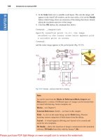
1. Construct a 3D model of the wing nut shown in the two-view projec-
tion in Fig. 16.14.
Ø60
10
R10
2020
60
140
R2
R10
115
95
65
35
Tapped M45
Fig. 16.14 First example –
rendering – two-view projection
2. Place the 3D model in the 3D Views/Top view, Zoom to 1 and with
the Move tool, move the model to the upper part of the AutoCAD
drawing area.
3. Click the Create a point light tool icon in the Lights control panel
(Fig. 16.8). The Viewport Lighting Mode warning window appears
(Fig. 16.15). Click its Yes button.
4. A New Point Light icon appears and the command line shows:
Command: _pointlight
Specify source location Ͻ0,0,0Ͼ: enter .xy right-click of click at cen-
tre of model (need Z): enter 500 right-click
Enter an option to change [Name/Intensity/Status/shadoW/Attenu-
ation/Color/eXit] ϽeXitϾ: enter n (Name) right-click
Ch16-H8512.qxd 4/4/07 6:55 PM Page 263
264 Introduction to AutoCAD 2008
Enter light name ϽPointlight1Ͼ: right-click
Enter an option to change [Name/Intensity/Status/shadoW/Attenu-
ation/Color/eXit] ϽeXitϾ: right-click
Command:
5. Click the Create a distant light tool icon in the Lights control panel.
The command line shows:
Command: _distantlight
Specify light direction FROM Ͻ0,0,0Ͼ or [Vector]: enter .xy right-
click of click to the left and below the 3D model (need Z) enter 400
right-click
Specify light direction TO Ͻ1,1,1Ͼ: enter .xy right-click of click at
centre of mode (need Z) enter 70 right-click
Enter an option to change [Name/Intensity/Status/shadoW/Color/
eXit] ϽeXitϾ: enter n right-click
Enter light name ϽDistantlight1Ͼ: right-click
Enter an option to change [Name/Intensity/Status/shadoW/Color/
eXit] ϽeXitϾ: right-click
Command:
6. Place another Distant Light (Distantlight2) in the same position TO
and FROM the front and below the model at Z of 300.
Note
The Intensity of the lights can be set, Shadow can be set off or on in a
Sharp
or Soft setting, and the Color of a light can be changed as needed
in response to the prompts appearing when a light is added to a view.
7. When the model has been rendered if a light requires to be changed in
intensity, shadow, position or colour, click the Light list icon in the
Lights control panel and the LIGHTS IN MODEL palette appears.
Click a light name and the PROPERTIES palette for the light appears
in which modifications can be made (Fig. 16.16). Make any amend-
ments as thought necessary.
Fig. 16.15 The Viewpoint
Lighting Mode warning window
Ch16-H8512.qxd 4/4/07 6:55 PM Page 264
Rendering 265
Note
In this example the Intensity factor has been set at 5 for all three lights.
This is possible because the lights are close to the model. In larger size
models the Intensity factor may have to be set to a much higher figure.
Adding a material to a model
1. Click the Materials tool icon in the Materials control panel. The
MATERIALS palette appears (Fig. 16.17).
2. Click the Select Image button in the Diffuse map area of the
palette. The Select Image File dialog appears. Select Metals, Orna-
mental Metals, Copper from the Name list. Note the change in the
Available Materials in Drawing swatch at the top of the palette.
3. Right-click in the Available Materials in Drawing part of the palette
and click the Apply Material to Objects icon (Fig. 16.18).
4. Click any part of the 3D model to apply the material to the model.
5. Right-click in the Type field of the Material Editor – Global section
of the palette and select Realistic in the right-click menu (Fig. 16.19).
6. Click in the Global field and select the name of the material from the
popup list which appears. An Offset and Review part of the palette
appears showing the appearance of the material which has been
selected (Fig. 16.19). A click in either icon to the left or to the right in
Fig. 16.16 The LIGHTS IN
MODEL and PROPERTIES
palettes
Ch16-H8512.qxd 4/4/07 6:55 PM Page 265
266 Introduction to AutoCAD 2008
this field brings back the Materials Editor in which changes can be
made using the sliders against the features which can be adjusted.
7. Click the Render cropped region icon in the Render control panel
(Fig. 16.7, page 258) and window the 3D model. The model renders.
8. If necessary adjust the sliders in the Materials Editor – Global part
of the palette, rendering after each adjustment to obtain the best
possible rendering.
9. Click the Advanced Render Settings tool in the Render control
panel (Fig. 16.7, page 258) and in the palette which appears adjust
the Output size to 1024 ϫ 768 or to a larger size if possible
(Fig. 16.20).
10. Render the 3D model again and if now satisfied save to a suitable file
name.
Fig. 16.21 shows four renderings in the four Type settings.
Fig. 16.17 The MATERIALS
palette
Fig. 16.18 The Apply Material
to Objects icon
Fig. 16.19 The Offset and
Review area of the Materials
palette
Ch16-H8512.qxd 4/4/07 6:55 PM Page 266
Rendering 267
Fig. 16.20 Selecting an Output
size from the ADVANCED
RENDER SETTINGS palette
Fig. 16.21 First example –
Rendering
Ch16-H8512.qxd 4/4/07 6:55 PM Page 267
268 Introduction to AutoCAD 2008
Fig. 16.23 Second example –
Rendering
Note
The limited descriptions of rendering given in these pages do not show
the full value of different types of lights, materials and rendering meth-
ods. The reader is advised to experiment with the facilities available for
rendering.
Second example – rendering a 3D model (Fig. 16.23)
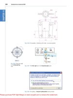
1. Construct 3D models of the two parts of the stand and support given in
the projections in Fig. 16.22 with the two parts assembled together.
2. Place the scene in the 3D Navigate/Top view, Zoom to 1 and add
lighting.
3. Add different materials to the parts of the assembly and render the
result.
Fig. 16.23 shows the resulting rendering.
Third example – rendering a 3D model (Fig. 16.25)
Fig. 16.24 is an exploded third angle orthographic projection of a pump-
ing device from a machine and Fig. 16.25 is an exploded and rendered 3D
model of the device.
The 3D Orbit tool
At the command line enter 3dorbit. The command line shows:
Command: 3dorbit
Press ESC or ENTER to exit, or right-click to display shortcut-menu.
R15
15
15
5
15
10
15
R50
R40
R45
60
20
5
70 20
20
170
300
165
100
130
100
10
Holes Ø8
Holes Ø10
Ø80
Fig. 16.22 Second example –
Rendering – projections of the
two parts
Ch16-H8512.qxd 4/4/07 6:55 PM Page 268
Rendering 269
Fig. 16.24 Third example –
Rendering – exploded
orthographic drawing
Right-click anywhere on screen and the 3dorbit right-click menu appears
(Fig. 16.26). Click Free Orbit. A circle and movement icon appears on
screen. The position and angle of the model can be adjusted by either
clicking in one of the four outer small circles or by clicking outside the
main circle and moving the mouse.
Ch16-H8512.qxd 4/4/07 6:55 PM Page 269
270 Introduction to AutoCAD 2008
Fig. 16.25 Third example –
Rendering – exploded and
rendered 3D model
Fig. 16.26 The right-click menu of
the 3dorbit tool
Example – 3D Orbit (Fig. 16.28)
This is another tool for the manipulation of 3D models into different posi-
tions within 3D space.
1. Open the file of the second example of rendering (Fig. 16.23).
2. Shade the model using Visual Styles/Realistic.
3. Enter 3dorbit at the command line.
4. With the cursor outside the circle move the mouse. The 3D model
rotates within the circle.
5. With the cursor inside the circle move the mouse. The 3D model
rotates around the screen.
6. With the cursor inside any one of the small quadrant circles the 3D
model can be moved vertically or horizontally as the mouse is moved
(Fig. 16.27).
Ch16-H8512.qxd 4/4/07 6:55 PM Page 270
Rendering 271
Fig. 16.27 Example – 3dorbit
Fig. 16.28 Example – 3dorbit the
example in a Four: Equal
viewport layout
7. Fit the 3D model into a Four: Equal viewports setting. Note that the
Visual Styles/Realistic mode still shows in each of the four viewports
(Fig. 16.28).
Ch16-H8512.qxd 4/4/07 6:55 PM Page 271
272 Introduction to AutoCAD 2008
Producing hardcopy
Printing or plotting a drawing on screen using AutoCAD 2008 can be car-
ried out from either Model Space or Paper Space. In versions of Auto-
CAD before AutoCAD 2004, it was necessary to print or plot from
PSpace.
First example – printing a single copy (Fig. 16.30)
Note
The drawing being printed in this example is in a Visual Styles/Concep-
tual shading mode.
1. With a drawing to be printed or plotted on screen click the Plot tool
icon in the Standard Annotation toolbar. (Fig. 16.29).
2. The Plot dialog appears. Set the Printer/Plotter to a printer or plotter
currently attached to the computer and the Paper Size to a paper size
to which the printer/plotter is set.
3. Click the Preview button of the dialog and if the preview is OK, right-
click and in the right-click menu which appears, click Plot. The draw-
ing plots producing the necessary ‘hardcopy’ (Fig. 16.30).
Second example – multiple view copy (Fig. 16.32)
A 3D model to be printed is a Realistic view of a 3D model which has
been constructed on three layers – Red, Blue and Green in colour. To
print a multiple view copy:
1. Place the drawing in a Four: Equal viewports setting.
2. Make a new layer vports of colour cyan and make it the current layer.
Fig. 16.30 First example – printing
a single copy
Fig. 16.29 Calling the Plot tool
from the Standard toolbar
Ch16-H8512.qxd 4/4/07 6:55 PM Page 272
Rendering 273
3. Click the Layout button in the status bar. The drawing appears in
PSpace. A view of the 3D model appears within a cyan-coloured
viewport (Fig. 16.31).
4. Click the Plot tool icon in the Standard Annotation toolbar. Make
sure the correct Printer/Plotter and Paper Size settings are selected
and click the Preview button of the dialog.
5. A preview of the 3D model appears.
6. If the preview is satisfactory (Fig. 16.32), right-click and from the
right-click menu click Plot. The drawing plots to produce the required
four-viewport hardcopy.
Other forms of hardcopy
When working in AutoCAD 2008, several different forms of hardcopy
can be printed or plotted determined by the settings in the 3D
Navigate/Visual Styles settings. As an example a single view plot pre-
view of the same 3D model is shown in the Hidden shading form
(Fig. 16.32).
Saving and opening 3D model drawings
3D model drawings are saved and/or opened in the same way as are 2D
drawings. To save a drawing click Save As in the File drop-down menu
and save the drawing in the Save Drawing As dialog and enter a file name
in the File Name field of the dialog before clicking the Save button. To
open a drawing which has been saved click Open in the File drop-down
Fig. 16.31 Second example
Multiple view copy – the Plot
Preview
Ch16-H8512.qxd 4/4/07 6:55 PM Page 273
274 Introduction to AutoCAD 2008
Fig. 16.32 An example of a
Hidden Style plot Preview
menu, and in the Select File dialog which appears select a file name from
the file list.
There are differences between saving a 2D and a 3D drawing, in that
when a 3D model drawing is shaded by using a shading mode from the
Visual Styles control panel, the shading is saved with the drawing.
Exercises
1. A rendering of an assembled lathe tool holder is shown in Fig. 16.33.
The rendering includes different materials for each part of the assem-
bly. Working to the dimensions given in the parts orthographic drawing
(Fig. 16.34), construct a 3D model drawing of the assembled lathe tool
holder on several layers of different colours, add lighting and materials
and render the model in an isometric view.
Fig. 16.33 Exercise 1 – a rendering
Ch16-H8512.qxd 4/4/07 6:55 PM Page 274
Rendering 275
Shade with 3D Visual Styles/Hidden and print or plot a Southwest
Isometric view of the model drawing.
2. Working to the sizes given in Fig. 16.35, construct a 3D model draw-
ing of the drip tray from an engine. Add lighting and a suitable mate-
rial, place the model in an isometric view and render (Fig. 16.36).
3. A three-view drawing of a hanging spindle bearing in third angle
orthographic projection is shown in Fig. 16.37. Working to the dimen-
sions in the drawing, construct a 3D model drawing of the bearing.
Add lighting and a material and render the model.
160 × Ø12
45
32
5
20
R4
R15
R30
30
115
90
20
11
Hole Ø8 C’bore Ø18
× 1 deep
Fig. 16.34 Exercise 1 – parts
drawing
R40
All 2
5
R70
Ø30
Ø20
280
3
2
R20
R13
25
140
40
15
Fig. 16.35 Exercise 2 – two-view
projection
Ch16-H8512.qxd 4/4/07 6:55 PM Page 275
276 Introduction to AutoCAD 2008
Fig. 16.36 Exercise 2
Ø120
Hole Ø60
25
95
70
30
1010
50
R40
190
240
R5
Holes Ø20
Ø120
Ø100
Ø100
20
R15
R20
R20
120
160
Semi-torus Ø10
Fig. 16.37 Exercise 3
Ch16-H8512.qxd 4/4/07 6:55 PM Page 276
277
CHAPTER 17
3D space
Aims of this chapter
1. To show in examples the methods of manipulating 3D models in 3D
space using tools from the UCS toolbars or from the command line.
2. To introduce some of the Surfaces tools.
3D space
So far in this book, when constructing 3D model drawings, they have
been constructed on the AutoCAD 2008 coordinate system which is based
upon three planes: the XY Plane – the screen of the computer; the XZ
Plane at right angles; to the XY Plane and as if coming towards the oper-
ator of the computer; and a third plane (YZ) is lying at right angles to
both the other two planes (Fig. 17.1).
Y
XY Plane
0,0,0
XZ Plane
Z
X
YZ Plane
Fig. 17.1 The 3D space planes
In earlier chapters in order to view 3D objects which have been con-
structed on these three planes at other angles we have used views from the
3D Navigate control panel and have indicated other methods of rotating
the model in 3D space and placing the model in other viewing positions
using the Vpoint Presets dialog and the 3dorbit tool.
Ch17-H8512.qxd 4/4/07 6:57 PM Page 277
278 Introduction to AutoCAD 2008
The User Coordinate System (UCS)
Note
The XY plane is the basic UCS plane, which in terms of the ucs is known
as the *WORLD* plane.
The UCS allows the operator to place the AutoCAD coordinate system
in any position in 3D space using a variety of UCS tools (commands).
Features of the UCS can be called either by entering ucs at the command
line, by selection from the Tools drop-down menu (Fig. 17.2) or from the
two UCS toolbars – UCS and UCS II (Fig. 17.3).
If ucs is entered at the command line, it shows:
Command enter ucs right-click
Current ucs name: *WORLD*
Enter an option [New/Move/orthoGraphic/Prev/Restore/Save/Del/
Apply/?/World] ϽWorldϾ: enter n (New) right-click
Specify origin of UCS or [ZAxis/3point/OBject/Face/View/X/Y/Z]
Ͻ0,0,0Ͼ:
And from these prompt lines a selection can be made.
The variable UCSFOLLOW
UCS planes can be set from either of the two UCS toolbars (Figs 17.2 and
17.3). For the UCS to operate from the command line, the variable UCS-
FOLLOW must first be set on as follows:
Fig. 17.2 The New UCS
submenu from the Tools
dropdown menu
Fig. 17.3 The tools from the two
UCS toolbars
Ch17-H8512.qxd 4/4/07 6:57 PM Page 278