Introduction to AutoCAD 2008 2D and 3D Design phần 10 pptx
Bạn đang xem bản rút gọn của tài liệu. Xem và tải ngay bản đầy đủ của tài liệu tại đây (3.71 MB, 29 trang )
330 Introduction to AutoCAD 2008
Fig. 20.13 Entering a request in the
InfoCenter field, followed by a
click on the InfoCenter icon
Click the Communication Center icon and another menu appears
from which choices may be made (Fig. 20.14).
Ch20-H8512.qxd 4/4/07 6:59 PM Page 330
Internet tools and Help 331
Fig. 20.14 The Communication
Center menu
Ch20-H8512.qxd 4/4/07 6:59 PM Page 331
332
CHAPTER 21
Design and AutoCAD 2008
Ten reasons for using AutoCAD
1. A CAD software package such as AutoCAD 2008 can be used to pro-
duce any form of technical drawing.
2. Technical drawings can be produced much more speedily using
AutoCAD than when working manually – probably as much as ten
times as quickly when used by skilled AutoCAD operators.
3. Drawing with AutoCAD is less tedious than drawing manually –
features such as hatching, lettering, adding notes, etc. are easier,
quicker and indeed more accurate.
4. Drawings or parts of drawings can be moved, copied, scaled,
rotated, mirrored and inserted into other drawings without having
to redraw.
5. AutoCAD drawings can be saved to a file system without necessarily
having to print the drawing. This can save the need for large drawing
storage areas.
6. The same drawing or part of a drawing need never be drawn twice,
because it can be copied or inserted into other drawings with ease.
A basic rule when working with AutoCAD is: Never draw the same
feature twice.
7. New details can be added to drawings or be changed within drawings
without having to mechanically erase the old detail.
8. Dimensions can be added to drawings with accuracy reducing the
possibility of making errors.
9. Drawings can be plotted or printed to any scale without having to
redraw.
10. Drawings can be exchanged between computers and/or emailed
around the world without having to physically send the drawing.
The place of AutoCAD 2008 in designing
The contents of this book are designed to help only those who have a lim-
ited (or no) knowledge of and skills in the construction of technical draw-
ings using AutoCAD 2008. However it needs to be recognised that the
impact of modern computing on the methods of designing in industry has
been immense. Such features as analysis of stresses, shear forces, bending
forces and the like can be carried out more quickly and accurately using
computing methods. The storage of data connected with a design and the
Ch21-H8512.qxd 4/4/07 6:59 PM Page 332
Design and AutoCAD 2008 333
ability to recover the data speedily are carried out much easier using com-
puting methods than prior to the introduction of computing.
AutoCAD 2008 can play an important part in the design process
because technical drawings of all types are necessary for achieving well-
designed artefacts whether it be an engineering component, a machine, a
building, an electronics circuit or any other design project.
In particular, 2D drawings, which can be constructed in AutoCAD 2008,
are still of great value in modern industry. AutoCAD 2008 can also be used
to produce excellent and accurate 3D models, which can be rendered to pro-
duce photographic-like images of a suggested design. Although not dealt
with in this book, data from 3D models constructed in AutoCAD 2008 can
be taken for use in computer-aided machining (CAM).
At all stages in the design process, either 2D or 3D drawings (or both) can
play an important part in aiding those engaged in designing to assist in
assessing the results of their work at various stages. It is in the design process
that drawings constructed in AutoCAD 2008 play an important part.
In the simplified design process chart shown in Fig. 21.1 an asterisk (*)
has been shown against those features where the use of AutoCAD 2008
can be regarded as being of value.
A design chart (Fig. 21.1)
The simplified design chart in Fig. 21.1 shows the following features:
Design brief: A design brief is a necessary feature of the design process. It
can be in the form of a statement, but it is usually much more. A design
brief can be a written report which not only includes a statement made
The problem
to be solved
Preliminary
drawings
The problem
to be solved
Preliminary
drawings
Notes with drawingsNotes with drawings
Statement with drawingsStatement with drawings
Specification with drawingsSpecification with drawings
Materials
Costs
Materials
Costs
Shape and FormShape and Form
ProportionsProportions
DrawingsDrawings
Technical drawingsTechnical drawings
TestsTests
Notes (including drawings)Notes (including drawings)
3D solid model drawings3D solid model drawings
GraphicsGraphics
Purpose
Methods
Purpose
Methods
Notes with drawingsNotes with drawings
Are they required?
For display
Are they required?
For display
TestsTests
GraphicsGraphics
ReportsReports
Planning
Sketches
Drawings
DESIGN BRIEF
RESEARCH
MODELS
CHOSEN SOLUTION
REALISATION
EVALUATION
IDEAS FOR
SOLVING BRIEF
Fig. 21.1 A simplified design chart
Ch21-H8512.qxd 4/4/07 6:59 PM Page 333
334 Introduction to AutoCAD 2008
of the problem which the design is assumed to be solving, but includes
preliminary notes and drawings describing difficulties which may be
encountered in solving the design and may include charts, drawings,
costings, etc. to emphasise some of the needs in solving the problem for
which the design is being made.
Research: The need to research the various problems which may arise when
designing is often much more demanding than that shown in the chart
(Fig. 21.1). For example the materials being used may require extensive
research as to costing, stress analysis, electrical conductivity, difficulties
in machining or in constructional techniques and other such features.
Ideas for solving the brief: This is where technical and other drawings
and sketches play an important part in designing. It is only after
research that designers can ensure the brief will be fulfilled.
Models: These may be constructed models in materials representing the
actual materials which have been chosen for the design, but in addition
3D solid model drawings, such as those which can be constructed in
AutoCAD 2008, can be of value. Some models may also be made in
the materials from which the final design is to be made so as to allow
testing of the materials in the design situation.
Chosen solution: This is where the use of drawings constructed in
AutoCAD 2008 are of great value. 2D and 3D drawings come into play
here. It is from such drawings that the final design will be manufactured.
Realisation: The design is made. There may be a need to manufacture a
number of the designs in order to enable evaluation of the design to be
fully assessed.
Evaluation: The manufactured design is tested in situations such as it is
liable to be placed in use. Evaluation will include reports and notes
which could include drawings with suggestions for amendments to the
working drawings from which the design was realised.
Enhancements in AutoCAD 2008
AutoCAD 2008 contains major enhancements over previous releases,
when working in either a 2D or a 3D environment. Please note that not all
the enhancements in AutoCAD 2008 are described in this introductory
book. Among the more important enhancements are the following:
1. The introduction of a 64-bit software edition of AutoCAD 2008 as
well as a 32-bit edition.
2. The introduction of a new workspace – 2D Drafting & Annotation.
3. Major changes to the DASHBOARD with the introduction of new
control panels.
4. Control panels now include 2D Draw, 3D Make, 2D Navigate,
Light, Visual Styles, Materials, Render, Layers, Annotation Scal-
ing, Text, Dimensions, Multi-leaders, Tables, 3D Navigate, Object
Properties and Block Attributes.
5. Multiple copies added to the Copy command.
6. Changes to methods of constructing sheet sets.
Ch21-H8512.qxd 4/4/07 6:59 PM Page 334
Design and AutoCAD 2008 335
7. New commands and set variables added.
8. Drawings constructed in MicroStation V8 can be imported and
exported into and from AutoCAD.
9. Some new dimension commands, including a new command
DIMBREAK with which dimension lines can be broken as they
cross features in a drawing.
10. Other enhancements in dimensioning.
11. Enhancements in Mtext.
12. Enhanced settings available in the Layer Settings dialog of the
Layer Properties Manager.
13. Some new commands and new system variables introduced.
14. New Help features in an InfoCenter (top right-hand corner of
AutoCAD 2008 window).
15. Changes to methods of rendering 3D solid model drawings, with the
introduction of new tools, new methods of lighting, adding materials,
shading and rendering. Changes in methods of applying materials and
lighting, including sun lighting.
16. Enhanced Materials palette allowing easier viewing and editing of
materials.
17. Many new materials added to the Textures folder.
18. A new command - render (the hyphen [-] must be included) allowing
use of the command line to set rendering presets.
19. Photometric lighting introduced akin to wattage in electric lights.
20. Of the new control panels, two have not been included in examples in
previous chapters – Annotation Scaling and Multi-leaders. Simple
examples of the use of tools from these control panels are given below.
Annotation scaling
Annotation scaling has many uses. This example shows only one of its
many uses.
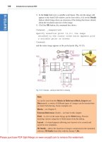
1. The drawing in Fig. 21.2 shows a scale 1:30 view of the front view of
a bungalow in Model Space in a Paper Space window.
2. Click the down-pointing arrow at the right-hand end of the status bar
and, in the menu which appears, note that the drawing has been con-
structed to a scale of 1:30 (Fig. 21.2).
3. Click 1:50 in the Annotation Scaling menu and the front view changes
to show a scale 1:50 front view (Fig. 21.3).
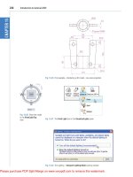
Multileaders
There are a variety of uses for mutlileaders. This example shows one such
use. The drawing in which multileaders are to be included is shown in
Fig. 21.4.
1. In the Multileaders control panel click the Multileader Style
Manager icon (Fig. 21.5). The dialog appears (Fig. 21.6).
Ch21-H8512.qxd 4/4/07 6:59 PM Page 335
336 Introduction to AutoCAD 2008
Fig. 21.3 First example –
Annotation Scaling. The front
view scaled to 1:50
Fig. 21.2 First example –
Annotation Scaling. The front
view of a bungalow drawn to a
scale of 1:30
2. In the dialog make entries as shown in Figs 21.6, 21.7 and 21.8.
3. Click Multileader icon in the control panel.
4. In the drawing, in response to prompts at the command line, add multi-
leaders one after the other to the drawing in Fig. 21.4, numbering the
parts 1 to 4. See Fig. 21.9.
Ch21-H8512.qxd 4/4/07 6:59 PM Page 336
Design and AutoCAD 2008 337
Fig. 21.4 Second example –
Multileaders. The drawing to
which multileaders are to be
added
Fig. 21.5 Second example –
Multileaders. The Multileader
Style Manager icon in the
Multileaders control panel
Fig. 21.6 Second example –
Multileaders. Settings in the
Leader Structure part of the
dialog
Ch21-H8512.qxd 4/4/07 7:00 PM Page 337
338 Introduction to AutoCAD 2008
Fig. 21.7 Second example –
Multileaders. Settings in the
Leader Format part of the
dialog
Fig. 21.8 Second example –
Multileaders. Settings in the
Content part of the dialog
System requirements for running AutoCAD 2008
Note
There are two editions of AutoCAD 2008 – 32-bit and 64-bit editions.
Operating system: Windows XP Professional, Windows XP Professional
(x64 Edition), Windows XP Home Edition, Windows 2000 or Windows
Vista 32 bit, Windows Vista 64 bit.
Ch21-H8512.qxd 4/4/07 7:00 PM Page 338
Design and AutoCAD 2008 339
Fig. 21.9 Second example –
Multileaders
Microsoft Internet Explorer 7.0.
Processor: Pentium III 800 Mhz.
RAM: At least 128 MB.
Monitor screen: 1024 ϫ 768 VGA with True Colour as a minimum.
Hard disk: A minimum of 300 MB.
Graphics card: An AutoCAD certified graphics card. Details can be found
on the webpage AutoCAD Certified Hardware XML Database.
Ch21-H8512.qxd 4/4/07 7:00 PM Page 339
340
APPENDIX A
Printing/Plotting
Introduction
Some suggestions for printing/plotting of AutoCAD drawings have already
been given (pages 272 to 274). Plotters or printers can be selected from a
wide range and are used for printing or plotting drawings constructed in
AutoCAD 2008. The example given here has been from a print using one of
the default printers connected to the computer used by the author. However
if another plotter or printer is connected to the computer, its driver can be set
by first opening the Windows Control Panel and with a double-click on the
Autodesk Plotter Manager icon the Plotters dialogs appears (Fig. A.1).
Fig. A.1 The Plotters window
Double-click on the Add, remove or change plotter properties icon
and the Plotter Configuration Editor dialog appears. Add settings as
required in the first of the dialogs from this editor (Fig. A.2). There are
several more dialogs in the series in which selections will need to be
made before completing the setting up of a printer or plotter for the print-
ing of AutoCAD drawings.
AppendixA-H8512.qxd 4/4/07 6:28 PM Page 340
Printing/Plotting 341
Fig. A.2 The first of the series of
Plotter Configuration Editor
dialogs
Fig. A.3 The Plot tool icon in the
Standard toolbar
Notes
1. AutoCAD drawings can be printed from the default printers already
installed in the Windows system of the computer on which AutoCAD
2008 is loaded.
2. Plots or prints from drawings constructed in AutoCAD 2008 can be
made from either Model Space or Paper Space.
An example of a printout
1. Either select Plot with a click on its tool icon in the Standard tool-
bar (Fig. A.3) or from the File drop-down menu. The Plot dialog
appears (Fig. A.4).
2. There are two parts in the Plot dialog. Fig. A.4 shows both the parts.
A click on the arrow at the bottom right-hand corner of the dialog
closes to reveal only the left-hand part and vice versa.
3. Select an appropriate printer or plotter from the Printer/plotter list. In
this example this is a colour printer. Then select the correct paper size
AppendixA-H8512.qxd 4/4/07 6:28 PM Page 341
342 Introduction to AutoCAD 2008
from the Paper size popup list. Then select what is to be printed/plot-
ted from the What to plot popup list – in the example shown this is
Display. Make sure the Landscape button is showing a dot (on). Click
the Properties button and in the Custom Properties dialog (not
shown) set Orientation to Landscape (dot in radio button). Then click
the Preview button of the Plot dialog.
4. A preview of the drawing to be printed/plotted appears (Fig. A.5). If sat-
isfied with the preview, right-click and from the menu which appears
click Plot. If not satisfied click Exit. The preview disappears and the
Plot dialog reappears. Make changes as required from an inspection of
the preview and carry on in this manner until a plot can be made.
Fig. A.5 The Plot Preview
window with its right-click menu
Fig. A.4 The Plot dialog
AppendixA-H8512.qxd 4/4/07 6:28 PM Page 342
343
APPENDIX B
List of tools
Introduction
AutoCAD 2008 allows the use of over 300 tools. Some operators prefer
using the word “commands”, although command as an alternative to tool
is not in common use today. The majority of these tools are described in
this list. Many of the tools described here have not been used in this
book, because this book is an introductory text designed to initiate read-
ers into the basic methods of using AutoCAD 2008. It is hoped the list
will encourage readers to experiment with those tools not described in the
book. The abbreviations for tools which can be abbreviated are included
in brackets after the tool name. Tool names can be entered in upper or
lower case.
A list of 2D tools is followed by a listing of 3D tools. Internet tools are
described at the end of this listing.
2D tools
About – Brings the About AutoCAD bitmap on screen
Appload – Brings the Load/Unload Applications dialog to screen
Adcenter (dc) – Brings the DesignCenter palette on screen
Align (al) – Aligns objects between chosen points
Arc (a) – Creates an arc
Area – States in square units the area selected from a number of points
Array (ar) – Creates Rectangular or Polar arrays in 2D
Ase – Brings the dbConnect Manager on screen
Attdef – Brings the Attribute Definition dialog on screen
Attedit – Allows editing of attributes from the Command line
Audit – Checks and fixes any errors in a drawing
Autopublish – Creates a DWF file for the drawing on screen
Bhatch (h) – Brings the Boundary Hatch dialog on screen
Block – Brings the Block Definition dialog on screen
Bmake (b) – Brings the Block Definition dialog on screen
Bmpout – Brings the Create Raster File dialog
Boundary (bo) – Brings the Boundary Creation dialog on screen
Break (br) – Breaks an object into parts
Cal – Calculates mathematical expressions
Chamfer (cha) – Creates a chamfer between two entities
AppendixB-H8512.qxd 4/11/07 4:54 AM Page 343
Chprop (ch) – Brings the Properties window on screen
Circle (c) – Creates a circle
Copytolayer – Copies objects from one layer to another
Copy (co) – Creates a single or multiple copies of selected entities
Copyclip (CtrlϩC) – Copies a drawing, or part of a drawing, for inserting
into a document from another application
Copylink – Forms a link between an AutoCAD drawing and its appearance
in another application such as a word-processing package
Customize – Brings the Customize dialog to screen, allowing the customi-
sation of toolbars, palettes, etc.
Dashboard – Brings the DASHBOARD to screen
Dashboardclose – Closes the DASHBOARD
Dblist – Creates a database list in a Text window for every entity in a drawing
Ddattdef (at) – Brings the Attribute Definition dialog to screen
Ddatte (ate) – Edits individual attribute values
Ddatext – Brings the Attribute Extraction dialog on screen
Ddcolor (col) – Brings the Select Color dialog on screen
Ddedit (ed) – The Text Formatting dialog box appears on selecting text
Ddim (d) – Brings the Dimension Style Manager dialog box on screen
Ddinsert (i) – Brings the Insert dialog on screen
Ddmodify – Brings the Properties window on screen
Ddosnap (os) – Brings the Drafting Settings dialog on screen
Ddptype – Brings the Point Style dialog on screen
Ddrmodes (rm) – Brings the Drafting Settings dialog on screen
Dd units (un) – Brings the Drawing Units dialog on screen
Ddview (v) – Brings the View dialog on screen
Del – Allows a file (or any file) to be deleted
Dgnexport – Creates a MicroStation V8 dgn file from the drawing on
screen
Dgnimport – Allows a MicroStation V8 dgn file to be imported as an
AutoCAD dwg file
Dim – Starts a session of dimensioning
Dimension tools – The Dimension toolbar contains the following tools –
Linear, Aligned, Arc Length, Ordinate, Radius, Jogged, Diameter,
Angular, Quick Dimension, Baseline, Continue, Quick Leader,
Tolerance, Center Mark, Dimension Edit, Dimension Edit Text,
Update and Dimension Style
Dim1 – Allows the addition of a single dimension to a drawing
Dist (di) – Measures the distance between two points in coordinate units
Distantlight – Creates a distant light
Divide (div) – Divides an entity into equal parts
Donut (do) – Creates a donut
Dsviewer – Brings the Aerial View window on screen
Dtext (dt) – Creates dynamic text. Text appears in drawing area as it is
entered
Dxbin – Brings the Select DXB File dialog on screen
Dxfin – Brings the Select File dialog on screen
Dxfout – Brings the Save Drawing As dialog on screen
344 Introduction to AutoCAD 2008
AppendixB-H8512.qxd 4/11/07 4:54 AM Page 344
Ellipse (el) – Creates an ellipse
Erase (e) – Erases selected entities from a drawing
Exit – Ends a drawing session and closes AutoCAD 2008
Explode (x) – Explodes a block or group into its various entities
Explorer – Brings the Windows Explorer on screen
Export (exp) – Brings the Export Data dialog on screen
Extend (ex) – To extend an entity to another
Fillet (f) – Creates a fillet between two entities
Filter – Brings the Object Selection Filters dialog on screen
Gradient – Brings the Hatch and Gradient dialog on screen
Group (g) – Brings the Object Grouping dialog on screen
Hatch – Allows hatching by the entry responses to prompts
Hatchedit (he) – Allows editing of associative hatching
Help – Brings the AutoCAD 2008 Help: User Documentation dialog on
screen
Hide (hi) – To hide hidden lines in 3D models
Id – Identifies a point on screen in coordinate units
Imageadjust (iad) – Allows adjustment of images
Imageattach (iat) – Brings the Select Image File dialog on screen
Imageclip – Allows clipping of images
Import – Brings the Import File dialog on screen
Insert (i) – Brings the Insert dialog on screen
Insertobj – Brings the Insert Object dialog on screen
Isoplane (Ctrl/E) – Sets the isoplane when constructing an isometric
drawing
Join (j) – Joins lines which are in line with each other or arcs which are
from the same centre point
Laycur – Changes layer of selected objects to current layer
Laydel – Deletes and purges a layer with its contents
Layer (la) – Brings the Layer Properties Manager dialog on screen
Layout – Allows editing of layouts
Lengthen (len) – Lengthens an entity on screen
Limits – Sets the drawing limits in coordinate units
Line (l) – Creates a line
Linetype (lt) – Brings the Linetype Manager dialog on screen
List (li) – Lists in a text window details of any entity or group of entities
selected
Load – Brings the Select Shape File dialog on screen
Ltscale
(lts) – Allows the linetype scale to be adjusted
Measure (me) – Allows measured intervals to be placed along entities
Menu – Brings the Select Menu File dialog on screen
Menuload – Brings the Menu Customization dialog on screen
Mirror (mi) – Creates an identical mirror image of selected entities
Mledit – Brings the Multiline Edit Tools dialog on screen
Mline (ml) – Creates mlines
Mlstyle – Brings the Multiline Styles dialog on screen
Move (m) – Allows selected entities to be moved
Mslide – Brings the Create Slide File dialog on screen
List of tools 345
AppendixB-H8512.qxd 4/11/07 4:54 AM Page 345
Mspace (ms) – When in PSpace changes to MSpace
Mtext (mt or t) – Brings the Multiline Text Editor on screen
Mview (mv) – To make settings of viewports in Paper Space
Mvsetup – Allows drawing specifications to be set up
New (CtrlϩN) – Brings the Select template dialog on screen
Notepad – For editing files from the Windows 95 Notepad
Offset (o) – Offsets selected entity by a stated distance
Oops – Cancels the effect of using Erase
Open – Brings the Select File dialog on screen
Options – Brings the Options dialog to screen
Ortho – Allows ortho to be set ON/OFF
Osnap (os) – Brings the Drafting Settings dialog to screen
Pagesetup – Brings either the Page Setup Model or Page Setup-Layout1
dialog to screen for setting print/plot parameters
Pan (p) – Drags a drawing in any direction
Pbrush – Brings Windows Paint on screen
Pedit (pe) – Allows editing of polylines. One of the options is Multiple
allowing continuous editing of polylines without closing the command
Pline (pl) – Creates a polyline
Plot (CtrlϩP) – Brings the Plot dialog to screen
Point (po) – Allows a point to be placed on screen
Polygon (pol) – Creates a polygon
Polyline (pl) – Creates a polyline
Preferences (pr) – Brings the Options dialog on screen
Preview (pre) – Brings the print/plot preview box on screen
Properties – Brings the Properties palette on screen
Psfill – Allows polylines to be filled with patterns
Psout – Brings the Create Postscript File dialog on screen
Purge (pu) – Purges unwanted data from a drawing before saving to file
Qsave – Saves the drawing file to its current name in AutoCAD 2008
Quickcalc (qc) – Brings the QUICKCALC palette to screen
Quit – Ends a drawing session and closes down AutoCAD 2008
Ray – A construction line from a point
Recover – Brings the Select File
dialog on screen to allow recovery of
selected drawings as necessary
Recoverall – Repairs damaged drawing
Rectang (rec) – Creates a pline rectangle
Redefine – If an AutoCAD command name has been turned off by
Undefine, Redefine turns the command name back on
Redo – Cancels the last Undo
Redraw (r) – Redraws the contents of the AutoCAD 2008 drawing area
Redrawall (ra) – Redraws the whole of a drawing
Regen (re) – Regenerates the contents of the AutoCAD 2008 drawing
area
Regenall (rea) – Regenerates the whole of a drawing
Region (reg) – Creates a region from an area within a boundary
Rename (ren) – Brings the Rename dialog on screen
346 Introduction to AutoCAD 2008
AppendixB-H8512.qxd 4/11/07 4:54 AM Page 346
Replay – Brings the Replay dialog on screen from which bitmap image files
can be selected
Revcloud – Forms a cloud-like outline around objects in a drawing to
which attention needs to be drawn
Save (CtrlϩS) – Brings the Save Drawing As dialog box on screen
Saveas – Brings the Save Drawing As dialog box on screen
Saveimg – Brings the Save Image dialog on screen
Scale (sc) – Allows selected entities to be scaled in size – smaller or
larger
Script (scr) – Brings the Select Script File dialog on screen
Setvar (set) – Can be used to bring a list of the settings of set variables
into an AutoCAD Text window
Shape – Inserts an already loaded shape into a drawing
Shell – Allows MS-DOS commands to be entered
Sketch – Allows freehand sketching
Solid (so) – Creates a filled outline in triangular parts
Spell (sp) – Brings the Check Spelling dialog on screen
Spline (spl) – Creates a spline curve through selected points
Splinedit (spe) – Allows the editing of a spline curve
Stats – Brings the Statistics dialog on screen
Status – Shows the status (particularly memory use) in a Text window
Stretch (s) – Allows selected entities to be stretched
Style (st) – Brings the Text Style dialog on screen
Tablet (ta) – Allows a tablet to be used with a pointing device
Tbconfig – Brings the Customize dialog on screen to allow configuration
of a toolbar
Text – Allows text from the Command line to be entered into a drawing
Thickness (th) – Sets the thickness for the Elevation command
Tilemode – Allows settings to enable Paper Space
Tolerance – Brings the Geometric Tolerance dialog on screen
Toolbar (to) – Brings the Toolbars dialog on screen
Trim (tr) – Allows entities to be trimmed up to other entities
Type – Types the contents of a named file to screen
UCS – Allows selection of UCS (User Coordinate System) facilites
Undefine – Suppresses an AutoCAD command name
Undo (u) (CtrlϩZ) – Undoes the last action of a tool
View – Brings the View dialog on screen
Vplayer – Controls the visibility of layers in Paperspace
Vports – Brings the Viewports dialog on screen
Vslide – Brings the Select Slide File dialog on screen
Wblock (w) – Brings the Create Drawing File dialog on screen
Wmfin – Brings the Import WMF File dialog on screen
Wipeout – Forms a polygonal outline within which all crossed parts of
objects are erased
Wmfopts – Brings the Import Options dialog on screen
Wmfout – Brings the Create WMF dialog on screen
Xattach (xa) – Brings the Select Reference File dialog on screen
List of tools 347
AppendixB-H8512.qxd 4/11/07 4:54 AM Page 347
Xline – Creates a construction line
Xref (xr) – Brings the Xref Manager dialog on screen
Zoom (z) – Brings the zoom tool into action
3D tools
3darray – Creates an array of 3D models in 3D space
3dface (3f) – Creates a 3- or 4-sided 3D mesh behind which other features
can be hidden
3dmesh – Creates a 3D mesh in 3D space
3dcorbit – Allows methods of manipulating 3D models on screen
3ddistance – Allows the controlling of the distance of 3D models from
the operator
3dfly – Allows walkthroughs in any 3D plane
3dforbit – Controls the viewing of 3D models without constraint
3dmove – Shows a 3D move icon
3dorbit (3do) – Allows a continuous movement and other methods of
manipulation of 3D models on screen
3dorbitctr – Allows further and a variety of other methods of manipulation
of 3D models on screen
3dpan – Allows the panning of 3D models vertically and horizontally on
screen
3drotate – Displays a 3D rotate icon
3dsin – Brings the 3D Studio File Import dialog on screen
3dsout – Brings the 3D Studio Output File dialog on screen
3ddwf – Brings up the Export 3D DWF dialog
3dwalk – Starts walk mode in 3D
anipath – Opens the Motion Path Animation dialog
Align – Allows selected entities to be aligned to selected points in 3D
space
Ameconvert – Converts AME solid models (from Release 12) into AutoCAD
2000 solid models
Box – Creates a 3D solid box
Cone – Creates a 3D model of a cone
convertoldlights – Converts lighting from previous releases to AutoCAD
2008 lighting
convertoldmaterials – Converts materials from previous releases to
AutoCAD 2008 materials
convtosolid – Converts plines and circles with thickness to 3D solids
convtosurface – Converts objects to surfaces
Cylinder – Creates a 3D cylinder
Dducs (uc) – Brings the UCS dialog on screen
Edgesurf – Creates a 3D mesh surface from four adjoining edges
Extrude (ext) – Extrudes a closed polyline
Flatshot – Creates flattened view
Freepoint – Point light created without settings
Freespot – Spot light created without settings
Helix – Constructs a helix
348 Introduction to AutoCAD 2008
AppendixB-H8512.qxd 4/11/07 4:54 AM Page 348
Interfere – Creates an interference solid from selection of several
solids
Intersect (in) – Creates an intersection solid from a group of solids
Light – Brings the Lights dialog on screen
Lightlist – Opens the Lights in Model Space palette
Loft – Activates the Loft command
Materials – Opens the Materials palette
Matlib – Brings the Materials Library dialog on screen
Mirror3d – Mirrors 3D models in 3D space in selected directions
Mview (mv) – When in PSpace brings in MSpace objects
Pface – Allows the construction of a 3D mesh through a number of
selected vertices
Plan – Allows a drawing in 3D space to be seen in plan (UCS World)
Planesurf – Creates a planar surface
Pointlight – Creates a Point light
Pspace (ps) – Changes MSpace to PSpace
Pyramid – Creates a pyramid
Renderpresets – Opens the Render Presets Manager dialog
Renderwin – Opens the Render window
Revolve (rev) – Forms a solid of revolution from outlines
Revsurf – Creates a solid of revolution from a pline
Rmat – Brings the Materials dialog on screen
Rpref (rpr) – Brings the Rendering Preferences dialog on screen
Rulesurf – Creates a 3D mesh between two entities
Scene – Brings the Scenes dialog on screen
Section (sec) – Creates a section plane in a 3D model
Shade (sha) – Shades a selected 3D model
Slice (sl) – Allows a 3D model to be cut into several parts
Solprof – Creates a profile from a 3D solid model drawing
Sphere – Creates a 3D solid model sphere
Spotlight – Creates a spotlight
Stlout – Saves a 3D model drawing in ASCII or binary format
Sunproperties – Opens the Sun palette
Sunstudywizard – Creates a sun study through a wizard
Torus (tor) – Allows a 3D torus to be created
Ucs – Allows settings of the UCS plane
-render – Can be used to make rendering settings from the command
line. Note the hyphen (-) must preceed render
Sweep – Creates a 3D model from a 2D outline along a path
Tabsurf
– Creates a 3D solid from an outline and a direction vector
Ucs – Allows settings of the UCS plane
Union (uni) – Unites 3D solids into a single solid
View – Creates view settings for 3D models
Visualstyles – Opens the Visual Styles palette
Vpoint – Allows viewing positions to be set from x,y,z entries
Vports – Brings the Viewports dialog on screen
Wedge (we) – Creates a 3D solid in the shape of a wedge
Xedges – Creates a 3D wireframe for a 3D solid
List of tools 349
AppendixB-H8512.qxd 4/11/07 4:54 AM Page 349
Internet tools
Browse the Web – Brings Autodesk home page from the Internet on
screen
Etransmit – Brings the Create Transmittal dialog to screen
Publish – Brings the Publish to Web dialog to screen
350 Introduction to AutoCAD 2008
AppendixB-H8512.qxd 4/11/07 4:54 AM Page 350
351
APPENDIX C
Some of the set variables
Introduction
AutoCAD 2008 is controlled by a large number of variables (over 460 in
number), the settings of many of which are determined when making
entries in dialogs. Others have to be set at the command line. Some are
read-only variables which depend upon the configuration of AutoCAD
2008 when it originally loaded into a computer (default values).
A list of those set variables follows which are of interest in that they
often require setting by entering figures or letters at the command line. To
set a variable, enter its name at the command line and respond to the
prompts which arise.
To see all set variables, enter set (or setvar) at the command line:
Command: enter set right-click
SETVAR Enter variable name or ?: enter ?
Enter variable name to list Ͻ*Ͼ: right-click
And a Text window opens showing a first window with a list of the first of
the variables. To continue with the list press the Return key when prompted
and at each press of the Return key another window opens.
To see the settings for each set variable enter the name of the variable
at the command line, followed by pressing the F1 key which brings up the
Help screen, click the search tab, followed by entering set variables in the
Ask field. From the list then displayed the various settings of all set vari-
ables can be read.
Some of the set variables
ANGDIR – Sets angle direction. 0 counterclockwise; 1 clockwise
APERTURE – Sets size of pick box in pixels
AUTODWFPUBLISH – Sets Autopublish on or off
BLIPMODE – Set to 1 marker blips show; set to 0 no blips
COMMANDLINE – Opens the command line palette
COMMANDLINEHIDE – Closes the command line palette
COPYMODE – Sets whether Copy repeats
AppendixC-H8512.qxd 4/11/07 4:54 AM Page 351
Note
DIM variables – There are over 70 variables for setting dimensioning, but
most are in any case set in the Dimension Style dialog or as dimension-
ingproceeds. However one series of the Dim variables may be of interest.
DMBLOCK – Sets a name for the block drawn for an operator’s own
arrowheads. These are drawn in unit sizes and saved as required
DIMBLK1 – Operator’s arrowhead for first end of line
DIMBLK2 – Operator’s arrowhead for other end of line
DRAGMODE – Set to 0 no dragging; set to 1 dragging on; set to 2 auto-
matic dragging
DRAG1 – Sets regeneration drag sampling. Initial value is 10
DRAG2 – Sets fast dragging regeneration rate. Initial value is 25
FILEDIA – Set to 0 disables Open and Save As dialogs; set to 1 enables
these dialogs
FILLMODE – Set to 0 hatched areas are filled with hatching. Set to 0
hatched areas are not filled. Set to 0 and plines are not filled.
GRIPS – Set to 1 and grips show. Set to 0 and grips do not show.
LIGHTINGUNITS – Set to 1 (international) or 2 (USA) for photometric
lighting to function
MBUTTONPAN – Set to 0 no right-click menu with the Intellimouse.
Set to 1 Intellimouse right-click menu on
MIRRTEXT – Set to 0 text direction is retained; set to 1 text is mirrored
PELLIPSE – Set to 0 creates true ellipses; set to 1 polyline ellipses
PICKBOX – Sets selection pick box height in pixels
PICKDRAG – Set to 0 selection windows picked by two corners; set to 1
selection windows are dragged from corner to corner.
RASTERPREVIEW – Set to 0 raster preview images not created with
drawing. Set to 1 preview image created
SHORTCUTMENU – For controlling how
right-click menus show: 0 all
disabled; 1 default menus only; 2 edit mode menus; 4 command mode
menus; 8 command mode menus when options are currently available.
Adding the figures enables more than one option
SURFTAB1 – Sets mesh density in the M direction for surfaces gener-
ated by the Surfaces tools
SURFTAB2 – Sets mesh density in the N direction for surfaces generated
by the Surfaces tools
TEXTFILL – Set to 0 True Type text shows as outlines only; set to 1
True Type text is filled
TILEMODE – Set to 0 Paper Space enabled; set to 1 tiled viewports in
Model Space
TOOLTIPS – Set to 0 no tool tips; set to 1 tool tips enabled
TPSTATE – Set to 0 and the Tool Palettes window is inactive. Set to 1
and the Tool Palettes window is active
TRIMMODE – Set to 0 edges not trimmed when Chamfer and Fillet are
used; set to 1 edges are trimmed
UCSFOLLOW – Set to 0 new UCS settings do not take effect; set to 1
UCS settings follow requested settings
UCSICON – Set OFF UCS icon does not show; set to ON it shows
352 Introduction to AutoCAD 2008
AppendixC-H8512.qxd 4/11/07 4:54 AM Page 352
353
*.dwf file, 181
*.dwt, 14
*.dxf files, 166
*.eps files, 164
2D coordinates, 12
2D Drafting & Annotation
workspace, 4, 22
2D Draw control panel, 3, 5, 22
2D Draw toolbar, 17
2D drawings, 333
2D objects in 3D space, 284
2D outlines for 3D, 199
3 Point UCS, 282
3
1
⁄
2
floppy disk, 44
3D Array tool, 236
3D blocks, 231
3D coordinates, 13
3D model libraries, 231
3D model views, 243
3D Modeling workspace, 4
3D modelling, 195
3D models, 220, 234, 333
3D Navigate control panel, 198, 202
3D Orbit tool, 268
3D Space, 277
3D Studio, 169
3D Surfaces, 210, 248
3D template, 254
3D tools, 196
3D Views, 5
3D Wireframe, 254
64 bit AutoCAD, 334
A1 sheet sizes, 80
Abbreviations for tools, 40
Abbreviations Modify tools, 99
Absolute coordinate entry, 26, 36
Acadiso.dwt, 14, 65
Acadiso3D screen, 256
Acadiso3D.dwt, 195
Adding materials, 265
Additional Resources, 328
Advanced hatching, 142
ADVANCED RENDER SETTINGS
palette, 262
Advanced Render Settings tool, 266
Aerial View window, 67
Aligned dimensions, 108
All zoom, 66
Ambient light, 257
Angular dimensions, 110
Annotation Scaling, 335
ANSI hatch patterns, 138
ANSI pattern, 130
Apply Material to Objects icon, 265
Arc Length tool, 113
Arc tool, 40
Arc tool icon, 40
Array tool, 85
Associative hatching, 140
Auto-hide icon, 8
AutoCAD 2008 enhancements, 333
AutoCAD 2008 window, 6
AutoCAD and designing, 332
AutoCAD Certified Hardware, 339
AutoCAD Classic workspace, 17
AutoCAD coordinate system, 12
AutoCAD SHX fonts, 119
AutoCAD Text Window, 119
AutoCAD workspace, 17
Autodesk Design Review dialog, 326
Autodesk DWF Viewer, 183
Autodesk Plotter Manager, 340
AutoSnap, 40, 44, 48
Background, 254
Background dialog, 260
Block Definition dialog, 151
Blocks, 150
Bold fonts, 119
Boolean operators, 200
Box tool, 204
Index
Index-H8512.qxd 4/12/07 12:28 AM Page 353
Break tool, 95
Browse for Drawing File dialog, 158
Building drawing, 186
Buttons, 11
CAM, 333
Center zoom, 66
Centre lines, 126
Chamfer tool, 98, 207
Check boxes, 11
Check Spelling dialog, 122
Checking spelling, 121
Circle tool, 28
Circle tool icon, 28
Classic workspace, 4
Clean Screen button, 12
Clean Screen icon, 51
Click, 36
Clipboard viewer, 163
Close drawing button, 23
Color faces tool, 301
Colour gradient hatching, 141
Command line, 59
Command line dimensions, 109
Command palette, 4
Command palette control, 20
Command palette entries, 16
Commandlinehide, 51
Communication Center, 330
Computer-aided machining, 333
Conceptual shading, 232
Control panels, 8, 334, 340
Coordinate entry, 36
Coordinate points, 26
Coordinate system, 12
Copy, 210
Copy faces tool, 300
Copy Link tool, 162
Copy tool, 81, 164
Copy with Base Point tool, 164
Create distant light tool icon, 264
Create Sheet Set dialogs, 179
Create Transmittal dialog, 327
Ctrl ϩ 9, 20, 51
Ctrl ϩ E keys, 131
Cylinder tool, 205
DASHBOARD, 5, 18, 59, 195
DASHBOARD palette, 8
Data Exchange Format files, 166
Default template, 254
Deferred tangent tip, 30
354 Index
Design, 332
Design brief, 333
Design chart, 333
Design research, 334
Design Web Format file, 181
DesignCenter, 154, 158, 232
DesignCenter palette, 7
Dgnexport, 172
Dgnimport, 172
Dialog, 9, 36
Digitiser, 6
Dimension abbreviations, 109
Dimension Style, 70
Dimension tolerances, 114
Dimension tools, 106
Dimensions, 106
Dimensions from command line, 109
Dimensions toolbar, 107
Dimlinear tool, 107
Display sub-menu, 6
Distant light, 258
Docking DASHBOARD, 19
Double-click, 36
Drafting Settings dialog, 45, 51
Drag, 36
Draw control panel, 17
Draw drop-down menu, 201
Draw toolbar, 17
Draw tools, 40
Drawing templates, 14, 69
Drawing Utilities, 156
Drop-down menu, 36
DUCS, 12
DWF file, 166, 181
DYN, 12, 44, 50, 60, 248
Dynamic Input, 12, 44, 50, 60, 118
Edgesurf tool, 288
Edit drop-down menu, 162
Edit Polyline tool, 56
Editing 3D solid models, 296
Editing dimensions, 112
Ellipse tool, 42
Ellipse tool icon, 42
Ellipses, 42
Elliptical cylinder, 209
Enable i-drop dialog 326
Encapsulated PS (*.eps), 164
End view, 126
Enhancements, 333
Enter key, 6
Erase tool, 30
Index-H8512.qxd 4/12/07 12:28 AM Page 354