LightWave 3D 8 Lighting Wordware game and graphics library phần 3 doc
Bạn đang xem bản rút gọn của tài liệu. Xem và tải ngay bản đầy đủ của tài liệu tại đây (1.41 MB, 55 trang )
back and forth. Once again, you can also hit the envelope button to the
right of the arrows and open a graph editor in which you can change the
intensity over time.
Below the intensity option are Intensity Falloff and Range/Nominal
Distance. You must set a distance and choose between four falloff types.
If you choose Off, the light intensity will remain the same whether the
light is one centimeter or one million kilometers away. If you choose any
of the other options, you will need to set the Range/Nominal Distance
parameter. This setting determines the maximum distance the light
reaches. For example, if I set a Linear falloff and a Range/Nominal
Distance of 10 meters, there would be no light transmitted from that
light 10 meters away from it. If I set Intensity Falloff to Linear, the light
intensity would be 100% at the center of the source, 50% five meters
from the source, and 0% 10 meters from the source. It is very linear and
refers to the distance at which light falloff ends. If the falloff parameter is
set to Inverse Distance or Inverse Distance^2, the Range/Nominal Dis-
tance refers to the distance at which light falloff begins.
Note: A linear falloff is not physically accurate, but it calculates
much more quickly than real light falloff, which is the inverse
square of the distance traveled by the light. It’s like this: A light
emits a specific quantity of light. When the light is near the light-
bulb, it is very dense and compressed together into a small area.
As the light travels away from the light, it spreads out and dissi-
pates. The light is less dense and, therefore, provides less
illumination on a surface.
You can also select a curved falloff shape instead of linear. You can
choose between inverse to the distance traveled or the inverse square of
the distance traveled. Inverse square is what occurs in nature, although I
have found that a linear falloff usually looks fine and seems to calculate
faster.
You will discover that you can apply intensity falloff to all light types
except distant lights. Falloff is not allowed for distant lights because a
distant light is supposed to simulate the sun. While the sun does indeed
have an intensity falloff, it is so astronomically huge (measured in mil
-
lions of light-years) that any amount of falloff occurring on our puny little
planet is probably immeasurable and certainly not visible. Smaller light
sources such as lightbulbs and candles have an easily visible intensity
falloff. If you light a candle in a dark room, you will see that there is a rel
-
atively intense area of light quite close to the candle that falls off quickly
Chapter 7
·······································
82
to dimness. If you stand outside this “circle of light” however, you will
see that the illumination still continues to the very walls of the room, no
matter how far away they are. It may be extremely dim light and may be
extremely difficult to see, but it is there. In reality, the light beams do
not stop at any range as they do in LightWave. They keep going and
spreading out until they can no longer be sensed by human visual sys
-
tems. The Range setting allows us to set a cap on how far away
LightWave calculates lighting. If we didn’t do this, renders might take a
very long time indeed.
Below the Range/Nominal Distance setting is Light Type. You have
five choices here: Distant, Point, Spot, Linear, and Area. All five of these
light types are covered in more detail later in this chapter.
Basic Sub-Tab
The first segment under the Light
Properties Basic sub-tab contains
four toggles (on/off switches) that
let you decide what aspects of the
scene your light will affect. The
Affect Diffuse button determines
whether or not the light will pro-
vide any illumination to the objects
in your scene, while the Affect
Specular button determines
whether or not the light will provide a specular light source for the sur
-
faces in the scene that have some amount of specularity turned on. In
the real world, Affect Diffuse and Affect Specular would be one and the
same (and so would reflectivity and glossiness, for that matter). In the
world of CG, however, we can use these qualities separately. Why? Say
you have a surface illuminated just exactly as you like it, but you wish
there was a higher specular highlight along one edge. In the real world,
you would not be able to increase the specular lighting without increas
-
ing the diffuse lighting, since it would be a simple matter of increasing
the overall intensity of the light. In LightWave, however, you could clone
your light source and turn off all affect attributes except Affect Specular.
That new light would now add additional specular intensity without
brightening up the surface of the object. The Affect OpenGL button
determines whether or not the illumination from the light will be visible
in Layout’s OpenGL viewports.
·······················
Light Types, Their Properties, and Typical Uses
83
Figure 7.3: The Basic sub-tab.
Note: Currently the maximum number of lights available in
OpenGL is eight. New to LightWave 8, the eight brightest lights will
be selected as the eight OpenGL lights, instead of the first eight
lights loaded. Or you can specify which eight lights you want to
affect OpenGL by using Affect OpenGL. Any illumination from
other lights will still be rendered but will not be visible in OpenGL.
The Affect Caustics button determines whether or not light emitted
from the light will be considered in any caustics calculations that may be
occurring in the scene, provided caustics has been turned on in the
Global Illumination panel.
Lens Flare/Lens Flare Options
The Lens Flare check box enables lens flares for the selected light and
also enables the Lens Flare Options button next to it. Clicking this but-
ton opens a new panel where you can adjust all the properties of the lens
flare. Lens flares are covered in more detail in Chapter 15.
Volumetric Lighting/Volumetric Light Options
The Volumetric Lighting check box enables lens flares for the selected
light and also enables the Volumetric Light Options button next to it.
Clicking this button opens a new panel where you can adjust all the
light’s volumetric properties. Volumetrics are covered in more detail in
Chapter 14.
Linear/Area Light Quality
Note: New to LightWave 8, Linear/Area Light Quality is now
envelopable. The most immediate advantage to this is that the
light quality can be tied to expressions. This means that you could
lower the light quality when the camera is very far away and
increase the quality as the camera draws near, thereby saving pre
-
cious render time when the camera is too far away to see the
better quality.
Linear and area lights are render intensive by nature. Because they cal
-
culate like linear or two-dimensional arrays of point lights, they take
much longer to render than LightWave’s simple lights (distant, point,
and spot). You can speed up your render times by lowering the quality of
the area or linear lights in your scene. This is especially good for
Chapter 7
·······································
84
rendering previews where final light quality is not so important. Also,
with Shading Noise Reduction enabled in the Global Illumination panel,
you may actually get away with lower quality settings for the final ren
-
der. The default quality setting is 4. The quality range for linear and area
lights is 1 to 5.
Spotlight Cone Angle
The Spotlight Cone Angle setting defines the angle from perpendicular
at which we find the edge of the light beam. If, for example, you set a
spotlight cone angle to 45 degrees, the total beam angle from one side to
the other would be 90 degrees. Make this angle smaller for a tighter
spotlight and larger for a wider spotlight. If you decided to make your
spotlight cone angle 180 degrees, your spotlight would behave some
-
what like a point light, emitting light in all directions.
If you use Light View in Layout, you will see that the spotlight cone
angle is defined by a shaded area around the outside of the spotlight
cone angle.
Spotlight Soft Edge Angle
The Spotlight Soft Edge Angle option determines how far inside the
cone angle the soft falloff begins. If you had a spotlight soft edge angle of
0 degrees, the spotlight edge would be hard. The higher the angle, the
softer the spotlight edge becomes. You can see the spotlight soft edge
angle as a dotted line inside the shaded area when using Layout’s Light
View.
·······················
Light Types, Their Properties, and Typical Uses
85
Figure 7.4: Looking through the Light View, you can see both
the spotlight cone angle and the spotlight soft edge angle. This
is a great way to set these angles if you are the type who
prefers to work visually rather than by the numbers.
The spotlight soft edge plays a major role in defining the scale of the
spotlight. Much larger or more distant light sources have a smaller soft
edge angle, while spotlight sources that are closer, diffused, or defocused
usually have a larger soft edge angle.
Projection Image
Note: New to LightWave 8, projection images are now visible
through the Light View. This makes it much easier to line up your
projection images just the way you’d like.
LightWave provides the ability to project an image through a spotlight
just like a slide projector or a film projector, depending on whether the
image is a still or an image sequence. This has many useful applications
such as projecting a background sequence onto some geometry at the
angle and position of your choice. You could always apply the image or
image sequence to the geometry, but projecting it through a spotlight
allows you to easily and quickly position the projected image anywhere
you like without having to rename surfaces to accommodate the image.
For more details and a tutorial on using projection images, please
see Chapter 10.
Shadows Sub-Tab
The first thing you will notice at the top of the Shadows sub-tab is the
Shadow Type menu. Clicking on this menu opens a drop-down that pro
-
vides three options: Off, Ray Trace, and Shadow Map. The options Off
Chapter 7
·······································
86
Figure 7.5: Projection image as viewed through the Light View.
and Ray Trace are available for all
lights. For spotlights, however, there
is a third option called Shadow Map.
You will soon discover that shadow
maps (and therefore spotlights) are
one of your best friends.
If you choose to leave shadows off
for a particular light, this means that
no shadows will be cast behind objects
on which that light is shining. The
object will still cast shadows on itself (provided you have not disabled
that option for the object in its properties panel), resulting in less illumi
-
nation on surfaces that are facing away from the light, but it will not cast
shadows on other objects or surfaces.
Ray tracing is calculated by tracing a line from the light source to the
edge of the object that casts the shadow. Many lines are traced from the
light source to the object until its entire shape has been traced with
these light “rays.” The result is an extremely hard-edged shadow that is
accurate in shape, if not in softness.
Shadow mapping is done by looking toward the object from the light,
taking the shape of the object in view (in this case a chair), and then
using that “shape” of light to illuminate surfaces and objects behind the
chair. It is not very physically accurate but has several significant advan
-
tages over ray tracing.
Beneath the Shadow Type selector is the Shadow Color box, used to
choose the color of your shadows. This can be a very cheap and easy
way of simulating a fill light without actually including one in the scene.
As we discovered earlier in this book, colored shadows are the result of
·······················
Light Types, Their Properties, and Typical Uses
87
Figure 7.6: The Light Properties
Shadows sub-tab.
Figure 7.7: This image demonstrates the three shadow states. The far left
image is rendered using a spotlight with shadows off, the middle image uses
ray tracing, and the right image uses a shadow map.
a secondary, or “fill,” light source providing additional illumination
within the shadow of the primary, or “key,” light source.
Note: Unfortunately, the shadow color only affects shadows
cast by one object onto another object and does not include
self-shadowing. This severely limits the use of shadow color in real
applications.
Everything beneath Shadow Color in the Shadows sub-tab relates only
to spotlights with shadow maps enabled. Shadow maps are one of the
most useful lighting tools in the LightWave lighting toolset for a number
of reasons: First, it is much, much faster to render with shadow-mapped
spotlights than to do all that ray tracing. Second, you have the option of
changing the resolution size of the shadow map. Keeping it as small as
possible provides the quickest render times; however, if the light is illu-
minating a very large area, you may begin to see pixelation, or “jaggies,”
in the shadows. This is corrected by making the shadow map resolution
larger. You will see the Shadow Map Size option a little farther down the
Shadows sub-tab. You can also add “fuzziness” to shadow maps using the
Shadow Fuzziness setting. This is a simple blurring algorithm that is
applied to the shadow map. It’s cheap and dirty but frequently passes for
natural soft shadows as photo-realistically as radiosity.
The Cache Shadow Map button tells LightWave to calculate the
shadow map only once, at the first frame of the render, then use that cal-
culation for all subsequent frames. If you have large shadow maps, or
many of them, and if your objects and lights do not move during the ani
-
mation, then this option could save you significant render time. It is like
casting a “freeze frame” shadow. If you use this option and your objects
or lights move, the shadow will not move with them but will stay in the
original place.
The Fit Spotlight Cone button, very simply, tells LightWave to make
the shadow map fit the spotlight cone angle, whatever angle that may be.
If you wish to choose your own size for the shadow map or zoom the
shadow map larger or smaller than the spotlight’s cone of illumination,
simply uncheck the box and enter the desired shadow map angle in the
box below. You can, for example, have a spotlight with a cone angle of 30
degrees and a shadow map with an angle of 5 degrees, or 90 degrees, or
whatever you wish.
Chapter 7
·······································
88
Note: If you use a smaller shadow map angle than the spot
-
light cone angle, you can see a representation of it in the Light
View of the spotlight. The secret is to use as small an angle as pos
-
sible for the shadow map while using as high a resolution as
needed.
More detail on all these tools is available in the LightWave manuals.
Objects Sub-Tab
Next to the Shadows sub-tab you
will find the Objects sub-tab. This is
pretty simple.
If you wish to exclude the cur
-
rently selected light from shining on
any particular object or objects, sim-
ply click the object in the Object list.
Note: In LightWave 8, you can now click in the gray bar (where
it says Exclude and Object) and you will get the option to select all,
clear all, or invert your selection. This comes in handy when you
want to select all but one object. It saves you from having to go
down the list selecting or deselecting everything. This same feature
is available in the Object Properties panel where you can exclude
lights from individual objects.
·······················
Light Types, Their Properties, and Typical Uses
89
Figure 7.8: The Objects sub-tab.
Figure 7.9: Object exclusion
options in the Light Properties
panel
Figure 7.10: Light exclusion options in
the Object Properties panel. Note you
can also exclude radiosity and caustics
calculations from individual objects.
Why would you wish to exclude a particular light from a particular
object? This is one of the true beauties of CG lighting. In the world of
real lights and electricity, one of the biggest problems is “spill” light —
undesired light falling on the subject. For example, you may be illuminat
-
ing a wall with one light and your foreground subject with another light.
You may not want the color or intensity of the wall light on your fore
-
ground subject. But if the foreground subject and the wall are very close,
spill is almost a foregone conclusion. Many devices have been invented
to deal with this problem including shutters, barn doors, and flags of var
-
ious shapes and sizes. In LightWave, however, all we have to do is click
the Exclude object list. Very nice, indeed!
The Global Illumination Button
Near the top of the Light Properties
panel is the Global Illumination button.
Clicking this button opens a new panel
filled with all sorts of good things.
Tread carefully here. While these
tools offer unparalleled photo-realism to
your lighting, they come at a cost of dras-
tically increased render times. Know
these four things:
•
You will be able to use these tools
occasionally when time permits.
•
Processors are always getting faster.
(When area lights were first
introduced, they were discarded as
useless due to the phenomenal rendering time required to calculate
their lighting solution.)
•
You don’t have to use these tools at the highest quality. Sometimes
you can get away with lower quality settings that render much
faster.
•
Sometimes you have to say “to hell with it” and crank everything up
just to enjoy yourself, then come back in the morning to view the
frame.
At the top of the panel are the Global Light Intensity and the Global
Lens Flare Intensity settings. These do exactly what they say. The
Global Light Intensity setting will allow you to control the intensity of all
lights at once. Beware, however, that if Light(1) is set to 100% and
Light(2) is set to 50% and you then make your Global Light Intensity
Chapter 7
·······································
90
Figure 7.11: The Global
Illumination panel.
50%, Light(1) will be emitting 50% and Light(2) will now be emitting
25%. In other words, the global setting does not override the light’s
intensity but reduces (or increases) it by the displayed percentage. It is
simply a multiplier that is applied to each light’s intensity value.
Global Lens Flare Intensity works exactly the same way but on lens
flares instead, if you have any activated in your scene.
The next three buttons allow you to toggle lens flares, volumetric
lights, and shadow maps. The practical use of these buttons is for mak
-
ing quick renders. Rather than going through each light individually and
disabling these features, you can turn all of them off at once with these
buttons, do your quick render, then easily enable them again later.
Ambient Light
There seems to have always been a raging controversy over the use of
ambient light for photo-real work. Why? Well, it seems to wash out the
image, reducing form and direction and flattening everything. This is
because ambient light adds a diffuse lighting value evenly to everything
in the scene. Why use it then? I mainly use ambient light to see what
I’m doing in OpenGL. Ambient light can also be an extremely quick ren-
dering solution for a global fill light if used properly. Most really good
artists will tell you to automatically turn off ambient lighting and use
“real” lights. While this has been largely true in the past, it is not so
now. Ambient light has been reborn as a tool to help with radiosity sce-
narios. We will get into more detail on this when we deal with radiosity
lighting solutions. Suffice it to say that it’s time to re-evaluate the old
ambient setting.
Here’s what Arnie Cachelin, senior programmer at NewTek, had to
say about it:
“Ambient intensity adds an even amount of diffuse lighting, so it will
be something like ambient*diffuse*color on a surface EXCEPT IN
THE CASE OF RADIOSITY RENDERING.
“With radiosity rendering, the ambient amount/color is used as a
background illumination amount, so the accessibility still applies, but
the ambient light makes up for the diffuse bounces skipped in the
indirect lighting calculation. This is why ambient is very useful in
radiosity rendering, and is actually a relatively accurate approxima
-
tion of scattered diffuse light.”
The more time I spend cranking out visual effects, the more uses I have
found for ambient intensity. While it is certainly to be used judiciously
and mainly where other, more elegant solutions are not possible for one
reason or another, don’t count it out entirely. It’s likely to save your
·······················
Light Types, Their Properties, and Typical Uses
91
bacon at some time. My latest experience was building talking animal
heads for a couple of feature films. We used Worley’s Sasquatch to fur all
our animals. Sasquatch is an extremely powerful tool, but simply due to
the nature of millions of fur fibers, we couldn’t render with ray tracing
on due to the immense rendering times. That’s fine, because Sasquatch
uses shadow maps. But the deepest shadows remained too deep, and we
couldn’t fill them ambiently using our usual methods: Backdrop Only
radiosity and area lights. The only real solution left was ambient inten
-
sity. The pleasant surprise was that since fur is so random and fine, you
couldn’t tell that the ambient intensity was flattening things out. It sim
-
ply decreased the shadow density perfectly and we went on our merry
way. I was so stuck on not using ambient intensity that it took me a long
time to get around to trying it. The lesson here is, don’t take anything
for granted. Don’t think you know everything, and be willing to try
things out, even if you think they probably won’t work. You might be as
pleasantly surprised as I was!
Shading Noise Reduction
Shading Noise Reduction is a great tool. As I am in the habit of using
area lights, it’s especially useful, as it allows me to set the light quality
lower and still achieve good results with faster rendering times. This
option reduces the graininess produced by linear and area lights. It also
reduces the graininess from radiosity with lower quality settings.
Radiosity and Caustics
The next two sections on the Global Illumination panel deal with
radiosity and caustics settings. If you want to jump right into it, they are
dealt with in depth in Chapters 12 and 13, respectively.
LightWave’s Light Types
Following is a description of the lights available in LightWave’s Layout.
Rather than simply quoting the manual, I try to put each light type into a
production context, describing the strengths and weaknesses of each,
providing real-world examples for each, and demonstrating some typical
uses for each light type.
Chapter 7
·······································
92
Distant Lights
Distant lights in LightWave are intended to simulate sunlight. The light
“rays” from a distant light are all parallel to each other, have no falloff,
and extend infinitely in whatever direction the light is pointed, so your
subject cannot travel out of the light as though it were lit by a spotlight.
While none of these properties exactly describe sunlight, they are simi
-
lar enough that a distant light can often pass for sunlight. It does not
················
Light Types, Their Properties, and Typical Uses
93
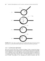
7.12: Shadows cast by a distant light are the same
shape as the object casting them. The shadow edges
are always hard.
7.13: Distant lights have a new look in LightWave 8.
This was done mainly to help differentiate spotlights
and distant lights.
matter where you position your distant light. It could be inside, below,
or above anything in the scene. The direction of the distant light is all
that matters. The direction of the distant light defines only the direction
of the light rays, not their origin.
What’s good about distant lights? They render relatively quickly,
even with ray-tracing on and they provide an adequate simulation for
direct sunlight.
What’s not so good? Because of the “ray-tracing only” shadows
option and the parallel rays, all shadows from this light are very
hard-edged. As we previously discussed, sunlight produces fairly hard
shadows close to an object, but the shadows become increasingly fuzzy
the farther away from the object the shadow is cast. This means a dis
-
tant light is not the best choice for a scene in which long shadows are
visible and need to be accurate. Because the light rays of a distant light
are all parallel, the shadows cast by an object will be exactly the same
size and shape as the object no matter how far away the shadow falls.
This is not very accurate but also may not be noticeable in many shots.
Practical uses for this light type include situations where the subject
is in the foreground and background shadows are not visible in frame
such as in a close-up.
Spotlights
Chapter 7
·······································
94
Figure 7.14: Spotlights also have a new look in
LightWave 8.
Spotlights are extremely versatile and useful lights. They are perhaps
the most useful lighting tool in the set. What makes them so special?
Well, spotlights can certainly be used just like a typical stage or studio
spotlight with a cone angle, shadow softness, gobos, shutters, and what
-
not. But they can also be transformed into fake point lights, area lights,
and distant lights, with the distinct advantage of utilizing shadow maps
and shadow fuzziness, meaning that they render much faster. But wait,
there’s more — unlike the real world, spotlights are not limited to spot
-
light cone angles within their lenses’ focal range. You can set a spotlight
to a cone angle of 180 degrees if you like, effectively creating a point
light or omnidirectional light source that can be shadow mapped. No ray
·······················
Light Types, Their Properties, and Typical Uses
95
Figure 7.16: A spotlight with shadow-mapped shadows
and a high shadow fuzziness.
Figure 7.15: A spotlight with ray-traced shadows.
tracing required. A warning, however: The higher you set the cone
angle, the larger your shadow map will need to be to avoid pixelation
(aka aliasing). Experiment with this and you will find the right balance.
Spotlights can also be used as fake distant or area lights. How? Sim
-
ply set the cone angle to an extremely small angle like 1 or 2 degrees,
back the light off until it is far away enough to cover your subject area,
and render away. The light rays are not quite as parallel as a distant light,
but they’re close. Once again, using a shadow map instead of ray tracing
will speed things up. As an added bonus, you can turn up the shadow
fuzziness to simulate a global or area light with very soft shadows.
These solutions will not always work for every situation, but I hope you
can see how versatile these lights can be and how easy it is to think up
different uses for them.
What’s wrong with spotlights? Well, there’s always a bad side. With ray
tracing on, the spotlight behaves exactly like a distant light except that
the light rays are diverging from a single point instead of being all paral
-
lel. Shadows are very hard. Shadow maps and fuzziness can solve much
of this, but they are not physically accurate and don’t always look right.
Furthermore, as I stated earlier, shadows tend to be sharper close to the
subject and softer farther away. Shadow maps are soft everywhere. It
can be a dead giveaway. Look again at Figure 7.7. The image on the right
shows a shadow-mapped shadow with a relatively high fuzziness level.
Note how the shadows do not touch the chair legs. They have been
“fuzzed out.” It’s a quick-and-dirty solution, but it can work if key areas
of the shadow are not visible in frame, hiding the inaccuracy.
Chapter 7
·······································
96
Figure 7.17: Note the apparent “radiosity” lighting on the columns and
ceiling. It appears that the light has come in through a window and
bounced off the floor, thus illuminating the ceiling and interior columns.
This radiosity effect was achieved using a single spotlight with a very wide
cone angle (85 degrees) and a high shadow fuzziness.
Point Lights
A point light is an omnidirectional source emitting from a nondimen
-
sional point in space. Some equate this to the sun or to a bare lightbulb.
Both of these are pretty much omnidirectional, but what makes them dif
-
ferent is that they both also have area or size, which a point light does
not. The difference is in the shadows. Point lights ray trace shadows,
which means that all shadows are very hard. There is no “penumbra”
·······················
Light Types, Their Properties, and Typical Uses
97
Figure 7.18: Surprise! Point lights have been
redesigned too. Not just a poor, back-alley asterisk
anymore. And besides, it’s a lot easier to tell the
difference between a point light and a null object
now. Good going, NewTek!
Figure 7.19: A point light.
effect and therefore no softening shadows. In fact, there are no light
sources in the real world that are nondimensional. Even the smallest fil
-
aments or arcs on the smallest light sources have some measure of size.
Now when we get into extremely small sources like LEDs, this point
becomes moot because you usually can’t see the difference, but if you
try to light a room with a bare lightbulb, the physical inaccuracies are
certain to be visible and obvious. The hard shadows of ray-traced lights
are one of the dead giveaways that elements are CG.
So what are point lights good for? I like to use them for point
sources where scale is very large and, therefore, the shadow details are
invisible. They’re excellent for this because, as ray-traced lights, they
render relatively quickly. And remember, you don’t have to have shad
-
ows turned on. You can use point lights as ambient or “fill” lights with
their shadows turned off if all you need is a little generic illumination.
Area Lights
Chapter 7
·······································
98
Figure 7.20: Guess what? Area lights have a new
look! That should help you tell the difference
between your white card and your area light. The
area lights now sport an arrow pointing from both
sides. This helps new users realize that area lights
light identically out of both sides.
Area lights are by far my favorite lighting tool. For one thing, they are far
more physically accurate than most any other light type in LightWave.
Second, they can be just about any light source you need simply by vary-
ing their size and shape. Third, they render more quickly than radiosity,
although they are significantly slower than ray-traced or shadow-mapped
lights. But the render hit is easily paid for by the beautiful quality of the
shadows. If render time were not an issue, I would probably light every-
thing with area lights and forget the rest of them.
What is an area light? It works somewhat like a rectangular space
that is filled with ray-traced point lights. The rays are tracing from over
the entire area of the rectangle, so light “wraps around” objects, creating
the “penumbra” effect, or soft, beautiful shadows. Because area lights
are based on an “area” of luminance, they are much more physically
accurate than any of the other light types in LightWave, which is why
the shadow quality is so realistic. If, for example, I used a large, distant
area light for the sun, the shadows would behave realistically, being hard
near the object and softening out farther away as opposed to a ray-traced
distant light, which would cause hard edged shadows everywhere. But a
large, distant area light will probably take a very long time to render, so
we make compromises, we cheat, we fake, we try to make it look as
close to “real” as possible, hopefully close enough that the audience
won’t see the difference. That said, area lights are still my favorite and
my most used lighting instrument of choice.
Area lights have a quality setting on the Basic sub-tab of the Light
Properties panel. Sometimes you can get away with a setting that is
lower than the default of 4. This will speed up your renders and is espe
-
cially great when doing test renders where final quality is not required.
·······················
Light Types, Their Properties, and Typical Uses
99
Figure 7.21: An area light.
Also, if you turn on Shading Noise Reduction on the Global Illumination
panel, it may allow you to keep your quality setting lower, thereby
reducing render times. Note that there is also a setting of 5 that is of
higher quality than the default of 4 for when you need it.
A great new tool in LW8 that applies to both area lights and linear
lights is that light quality is now envelopable. In other words, you can
make the area light quality low when the camera is very far away and
have it increase as the camera draws near. When the camera is far away,
you can’t tell the difference anyway, so why take all that extra render
time to calculate high quality when you can save it up for when the cam
-
era draws really near??!!
Note: If, like me, you use area lights all the time, then you
should know that G2 is just about the best investment you could
make. This is because G2 uses its own rendering engine to calcu
-
late area light shadows and includes, within its interface, an area
light shadow quality control. The resulting area light shadows on
G2 surfaces are far smoother and more beautiful than those from
LightWave alone. It is an expensive plug-in, but if quality is your
top concern, you really owe it to your clients. This one feature, in
my opinion, makes G2 worth the asking price. No, I am not get-
ting sales commissions! For more on G2, see Chapter 16.
Linear Lights
Chapter 7
·······································
100
Figure 7.22: Note that linear lights also have a new graphical
look. The new crosshairs at either end and at the middle of
the light make it easier to align the light in your scene.
Linear lights are similar to area lights except that instead of being a
two-dimensional rectangular array of point lights, they behave like a
one-dimensional line of point lights. The net effect of this setup is that a
linear light has an axis and that shadows cast will only be soft along that
one axis. It’s a rather strange shadow and not very useful in photo-real
work. Still, the linear light can be very useful with shadows turned off
when you need to simulate a light source such as a fluorescent tube. If I
had the time, however, I would choose a long, narrow area light to serve
as a fluorescent tube, as the shadows are much nicer.
Because linear lights only have to deal with one dimension of calcu-
lation, they calculate more quickly than area lights. As a matter of fact, if
one wished, one could create a quicker rendering area light by building
an array of linear lights side by side. Not as perfectly accurate as an area
light, but a good approximation in many cases, no doubt.
As mentioned previously, LW8 includes a new tool that allows you to
make both area lights and linear lights envelopable. Its use can save ren
-
der time.
·······················
Light Types, Their Properties, and Typical Uses
101
Figure 7.23: A linear light.
Objects as Lights
With the addition of radiosity to LightWave’s lighting toolset in version
6.0, CG artists were blessed with the ability to create custom lights in
any shape they wished. Radiosity is actually based on surfaces, not
objects, but that provides you with greater flexibility. Any surface with a
luminosity value will emit illumination into the scene if you have
radiosity turned on. The trade-off is that radiosity can be a painfully long
render. But used judiciously, this can still be an invaluable tool in your
search for photo-real perfection.
When you think about it, this feature makes sense. There are
numerous ways you can use radiosity. A lampshade, for example, might
appear luminous if it’s translucent. A neon sign or a frosted lightbulb
also fall into this category. Any item that is either luminous or translu
-
cent might be handled in this manner. Remember that small items in
your scene that use this technique will not necessarily automatically
make render times huge. There are a number of choices and settings in
the radiosity panel that will improve render times as well. So don’t write
off radiosity as too expensive. It’s a great tool and can make the differ
-
ence if you are trying to achieve photo-realism.
Perhaps the single greatest thing about this technique is that for the
first time, we can create physically accurate light sources in LightWave.
The simple lights — point, spot, and distant — are not physically accu
-
rate at all, and the complex lights — area and linear — only display some
physically accurate light properties. The main problem is that all light
sources are contained within a volume, such as a volume of flame or a
filament that makes up a physical volume in space. Volume, by definition,
Chapter 7
·······································
102
Figure 7.24
requires three dimensions. The most dimension any LightWave light
covers is two and that’s with the area light. Since we can emit light from
object shapes, we can create three-dimensional volumes, make them
luminous, and have them behave very much like real light sources in the
real world.
It’s not that you will have use for this very often, but it’s fun and
cool, and you can do some kick-ass lighting this way.
Examples
Following are a few examples illustrating the different looks from differ
-
ent light and shadow types. Area lights and radiosity are the most
attractive and accurate options but not the only ones. There are often
ways to create subtle, realistic solutions without them.
·······················
Light Types, Their Properties, and Typical Uses
103
Figure 7.25: In this image, a spotlight with high fuzziness has been
used as the key source. The shadows are fairly realistic along most
of the surface but not at the base.
Figure 7.26: An area light has been substitued as the key in this
image. Note the highly accurate shadows across the face and on
the wooden base.
All three of these examples are reasonably well lit. The question
becomes one of detail. What is the audience looking at? How long is the
shot? Long enough to notice the details? Does the camera zoom in on
any particular area?
If the audience has enough time to really notice the shadows, you’ll
likely want to go for a shadow-mapped or even an area light solution. If
it’s a short shot or if the camera simply pans past the object, you will
probably be able to get away with cheaper solutions. Remember, motion
blur hides many tricks.
This chapter has dealt with the different light types in the LightWave
toolset. Hopefully you now have a richer understanding of the qualities
and uses of these lights. I hope I have been able to provide a more
insightful and less technical view on them. Later chapters will go into
detail describing practical uses for each light type. In the meantime,
don’t be afraid to load up some of the sample scenes from the companion
CD and play with them. The absolute best way to know which light type
to use is to know the exact capabilities of each light type. I can write at
length what I think each light type is capable of, but it will never take the
place of your experience. This book is only half of the lesson; the rest is
up to you.
Chapter 7
·······································
104
Figure 7.27: The key light is a point light here. This still looks fairly
real, but all the shadows are hard due to the ray tracing and the
nondimensional point source of illumination.
Chapter 8
The LightWave
Color Picker
This chapter covers the different color picking tools available in
LightWave’s custom color picker. By the time you have finished this
chapter, you should have a good grasp of LightWave’s QuickColor,
HSV< >RGB, Tint & Shade, Wavelength, and Kelvin color pickers and
their specific uses.
LightWave comes equipped with
two choices for color pickers. You can
use the standard Windows or Mac color
picker, which is fairly basic, or you can
have a look at the arsenal of color pick-
ing tools in the LightWave color picker.
You can select the LightWave color
picker in Modeler by going to the Dis
-
play Options Interface tab and selecting
it in the Color Picker drop-down. In
Layout, open the General Options panel
and select from the Color Picker
drop-down.
Before we look at the LightWave
color picker, however, here are a few
words about color.
In your virtual world, there are two
primary reasons why a light source is
emitting a particular color of light.
In the first place, lights emit heat.
The higher the temperature, the brighter and whiter the light becomes.
The brightness is known as intensity and the color is known as color
temperature. Imagine a piece of metal heating up in a forge. It first
105
Figure 8.1: Selecting the
LightWave color picker in Layout’s
General Options panel.
begins to glow very dim red, then heats up to orange, then to white. If
you could keep heating it, it would start to go into the blue end of the
spectrum until it was too bright to look at. So low color temperatures
are in the red end of the spectrum while high color temperatures are in
the blue end of the spectrum with white in the middle. Ironically,
humans tend to equate blue with icy, cold things and red with fire and
brimstone, so we refer to colors in the red end as “warm” and colors in
the blue end as “cool,” which is completely backward. Just read it over a
couple of times — you’ll get it!
The second reason for a light’s color is that it may be filtered by
something. In other words, the light is passing through or reflecting off
some substance that is absorbing some of the color wavelengths and
allowing other wavelengths to pass through or reflect away. Take a piece
of green glass, for example. If you shine a white light through a piece of
green glass, the glass will absorb most of the red and blue wavelengths
from the light but will allow most of the green light to pass through.
Note: Why do I say “most” of the red and blue light is absorbed
and “most” of the green light passes through? In the theoretical
world, there are primary colors. Primary colors consist of only a
single pure wavelength. So if we had a pure white light that con-
sisted of all three primary colors (red, green, and blue), and if we
also had a green glass filter that only filtered out the primary red
and blue but allowed primary green to pass through, then we
could say all the red and blue was absorbed and all the green was
allowed to pass through. Trouble is, in the real world, primary col
-
ors don’t usually exist anywhere except laboratories. So while most
of the red and blue light is absorbed by the green filter, a little bit
will still seep through because the filter is not perfect. And while
most of the green light is allowed to pass through, some is
absorbed, again because the filter is not perfect. This may seem
like nit-picking, but understanding how imperfect light coloring
and filtering is in the real world can help you add realism to your
work. You can use numeric values to choose your technically per
-
fect colors, but you should trust your eyes to tell you whether or
not it looks right.
Almost all light is filtered by something. The sunlight is filtered by the
sky, the light in a neon sign is filtered by the colored glass tube, the floor
lamp light is filtered by its amber shade. You get the idea. Hopefully this
will help you make your color choices.
Chapter 8
·······································
106