Mastering Autodesk 3ds Max Design 2011 phần 4 pdf
Bạn đang xem bản rút gọn của tài liệu. Xem và tải ngay bản đầy đủ của tài liệu tại đây (3.43 MB, 97 trang )
266
|
CHAPTER 5 worKInG wIth external desIGn data
4. Back in the File Link Manager dialog box, click the Attach This File button. The contours
appear in the 3ds Max Perspective viewport, as shown in Figure 5.3.
5. Close the File Link Manager.
Turn Off the Grid If Necessary
You may want to toggle the grid off if it makes the scene appear too cluttered.
By linking an AutoCAD file, you keep the imported geometry associated with the original
AutoCAD file. As you’ll see a bit later, this link will enable you to update the 3ds Max scene
whenever changes occur to the AutoCAD file.
Now let’s see how the contours can be turned into a surface model:
1. Click the Select by Name button to open the Select from Scene dialog box. Select both
objects in the list; then click OK.
2. Make sure that the Geometry button is selected in the Create tab of the Command panel;
then choose Compound Objects on the Create drop-down list.
3. Click Terrain on the Object Type rollout.
Figure 5.4 shows the surface that appears over the contour lines.
Figure 5.3
The imported
contour lines in
the Perspective
viewport
Figure 5.4
The surfaces created
using the Terrain
compound object
CreatInG toPoGraPhY wIth sPlInes
|
267
3ds Max creates a Terrain object based on the contour lines. You can improve the visibility of
the terrain’s shape by using the Color by Elevation option:
1. In the Command panel, scroll down to the Color by Elevation rollout and open it.
2. Click the Create Defaults button in the Zones by Base Elevation group.
The Terrain object changes to show a series of colored bands, as shown in Figure 5.5.
The values in the Zones by Base Elevation list box tell you the base elevation for each of the
colors. You can change the color and the base elevation:
1. Select the first elevation value in the list box of the Zones by Base Elevation group.
2. In the Color Zone group, click the Base Color swatch.
3. In the Color Selector dialog box, click a cyan color in the Hue/Blackness field and then
click OK.
4. Click the Modify Zone button in the Color Zone group. The base of the Terrain object
changes to the cyan color you selected.
You can also change the vertical location for a color by changing the Base Elev value in the
Color Zone group. This doesn’t have any effect on the shape of the Terrain object; it only changes
the location of the color.
Figure 5.5
The contour line
surfaces shown as
a series of colored
bands
268
|
CHAPTER 5 worKInG wIth external desIGn data
Updating Changes from an AutoCAD File
You imported the AutoCAD contour map by clicking the Application menu and choosing the
References File Link Manager option. By using this option, you link your 3ds Max scene to
the contour.dwg file in a way that’s similar to XRef files in both 3ds Max and AutoCAD. The
conceptual difference between file linking and external references is that with XRefs, you are
bringing in native files, whereas with file linking, you are bringing in files that were made in
another application. Just as with changes made to an XRef, changes in the contour.dwg file will
affect any 3ds Max file to which it’s linked.
Let’s suppose that you have some corrections to make to the AutoCAD contour drawing that
will affect the Terrain object you’ve just created. You can change the AutoCAD drawing file and
then update the 3ds Max scene to reflect those changes:
1. If you have AutoCAD 2004 or later, open the contour.dwg file in AutoCAD and make the
changes shown in Figure 5.6. Save the file when you are done, overwriting the original.
2. If you don’t have AutoCAD, use Windows Explorer to delete the contour.dwg file; then
make a copy of the modified contour.dwg file and rename it contour.dwg to replace the
file you deleted. The modified contour.dwg file contains the changes shown in Figure 5.6.
3. In 3ds Max, click the Application menu and choose References File Link Manager.
4. In the File Link Manager dialog box, select the Files tab; then click the contour.dwg list-
ing in the Linked Files list box at the top of the dialog box.
5. Click the Reload button. The File Link Settings: DWG Files dialog box displays.
6. In the File Link Settings: DWG Files dialog box, click OK. The file is reloaded, and the
changes are applied in the current 3ds Max scene.
The Scene May Lose the Terrain Compound Object Parameters
Some installs of 3ds Max Design have a problem updating changes from AutoCAD regarding the
Terrain compound object. This is a known issue and is being looked into by Autodesk. If your file
doesn’t update properly (in other words, the Terrain compound object gets deleted), reselect the
two contour objects and re-create the Terrain compound object.
Figure 5.6
Stretch these
points outward.
Stretch these points.
CreatInG toPoGraPhY wIth sPlInes
|
269
7. Close the File Link Manager dialog box. The changes to the drawing are reflected in the
3ds Max scene. See Figure 5.7.
8. Save your terrain as Mycontours.max.
Like XRef files, 3ds Max scenes that are linked to AutoCAD files can be updated to reflect
changes that are made to the source AutoCAD file. You’ll get a chance to take a closer look at
this feature later in this chapter.
Exploring Terrain Options
The Terrain object has quite a few parameters that allow you to make adjustments to the ter-
rain. For example, if you prefer, you can have the terrain appear as a terraced form instead of a
smooth one, as shown in Figure 5.8.
The Layered Solid Option Is Similar to a Traditional Model
The Layered Solid option of the Terrain object creates a surface that resembles a traditional site-
plan physical model made of plywood, foamcore, or similar a material.
Figure 5.7
The modified DWG
file after reloading
it into the 3ds Max
scene
Figure 5.8
The Terrain object
with the Layered
Solid option. The
scene is shown ren-
dered for clarity.
270
|
CHAPTER 5 worKInG wIth external desIGn data
You’ve already seen how a few of the Color by Elevation rollout options work. Here’s a run-
down of the rest of the Terrain object parameters. These options allow you to add additional
splines to, or delete splines from, an existing Terrain object.
th e Pi c K oP e r a n d ro l l o u t
The Pick Operand rollout, shown in Figure 5.9, allows you to add other splines to an exist-
ing Terrain object. The splines used for the Terrain object are referred to as the operands of
the Terrain object. When a Terrain object is created, a Reference clone of the selected splines
is added as part of the Terrain object. This is the default option in the Pick Operand rollout.
When adding additional splines, you can choose the type of clone you want to use instead of the
Reference clone. The Override option lets you replace one operand with another.
th e Pa r a m e t e r S ro l l o u t
The Parameters Rollout, shown in Figure 5.10, offers settings that control the overall form of the
Terrain object. The Operands group lets you selectively delete operands from the terrain.
The Form group gives you control over the way the contour data is shaped into the terrain.
Graded Surface creates the type of terrain you’ve seen in previous exercises. Graded Solid cre-
ates a solid form that encloses the entire terrain, including the underside. Layered Solid creates
a terraced form. The Stitch Border option improves the formation of terrain where open splines
are used in the contour. Retriangulate helps to generate a terrain that follows the contours more
closely, especially when they are close together.
The Display group allows you to view the terrain as a surface terrain only, as contour lines
only, or as both. The default is to show only the terrain.
Figure 5.9
The Pick Operand
rollout
Figure 5.10
The Parameters
rollout
CreatInG toPoGraPhY wIth sPlInes
|
271
At the bottom of the rollout, the Update group lets you control the way that the Terrain object
is revised when the operands are edited. The Always option updates the Terrain object as soon
as a contour is modified. The When Rendering option updates when you render the scene. You
can also use the Update button with the Manually option to selectively update the terrain.
th e Si m P l i F i c a t i o n ro l l o u t
3ds Max uses the vertices of the original contour polylines to generate the Terrain object. The
Simplification rollout (see Figure 5.11) options give you control over the number of vertices used
to generate the terrain.
In the Horizontal group, both the Use 1/2 of Points option and the Use 1/4 of Points option
reduce the number of points used from the contour line. These procedures reduce the accuracy
of the terrain, but they also reduce the complexity of the geometry, thereby making the terrain’s
memory requirements smaller and rendering time shorter. The Interpolate Points options increase
the number of points used. Interpolate Points * 2, for example, doubles the number of vertices
used by interpolating new points between the existing points in the contour.
The Vertical group determines whether all of the selected contour lines are used. You can
reduce the terrain’s complexity by using either the Use 1/2 of Lines option or the Use 1/4 of
Lines option.
th e co l o r b Y el e V a t i o n ro l l o u t
3ds Max lets you color the Terrain object by elevation, using the rollout shown in Figure 5.12.
This enables you to visualize the terrain more clearly and helps you identify elevations by color-
coding them.
Figure 5.11
The Simplification
rollout
Figure 5.12
The Color by
Elevation rollout
272
|
CHAPTER 5 worKInG wIth external desIGn data
The Maximum Elev. and Minimum Elev. options display the maximum and minimum
extents of the terrain, based on the contour data. The Reference Elev. option lets you establish
a reference elevation that is used for assigning colors to the terrain. If this value is equal to or
less than the lowest contour, 3ds Max generates five color zones for the terrain, as you saw in an
earlier exercise. If the Reference Elev. is greater than the lowest contour, 3ds Max treats the lower
elevations as water, using the Reference Elev. value as the water level. Water is given a blue color
by default.
The Zones by Base Elevation group gives you control over the individual colors for each
color zone. As you’ve seen from the exercise, the Create Defaults button applies the colors to the
Terrain object based on the current settings of the rollout. You can also change the color of each
zone by selecting the zone elevation from the list box and using the Base Color swatch to select
a color.
The Blend to Color Above and Solid to Top of Zone options let you choose to blend colors
between zones or to have each zone one solid color. By default, colors are blended. You can
change from blended to solid by selecting the zone elevation from the Zones by Base Elevation
list, selecting Solid to Top of Zone, and then clicking the Modify Zones button. The Add Zone
and Delete Zone options add and delete zones.
Setting Up an AutoCAD Plan for 3ds Max
If you’re an experienced AutoCAD, Revit, AutoCAD Architecture, or AutoCAD Mechanical user,
you may find it easier to create at least part of your 3D model in your CAD program and then
import the model into 3ds Max to refine it. If this is the case, simply import or link the CAD
model into 3ds Max and then resume your design visualization workflow at the point of assign-
ing material, or adding lights and cameras. Then you can animate and render the scene.
On the other hand, you can also import 2D plans and elevations and build your 3D model
entirely in 3ds Max. In this section, you’ll explore the ways you can set up an AutoCAD or
AutoCAD LT 2D drawing to take advantage of 3ds Max’s superior modeling tools.
One of the drawbacks of importing fully developed 3D models from AutoCAD is that fre-
quently, the surface normals of the AutoCAD model are not all oriented in the proper direction.
You can use 3ds Max to adjust the normals to point in the correct direction, but that takes time.
In this situation, it’s sometimes more efficient to apply two-sided materials to the offending
objects and leave it at that. Using two-sided materials increases rendering time; however, this
disadvantage is often offset by the amount of time it would have taken to identify and adjust
misaligned normals. You can also use the Normal modifier or apply the Edit Poly modifier to
selected objects and adjust individual sub-objects in order to correct problems with surface
normals.
This is less of a problem when the 3D geometry is created in Revit and then linked into 3ds
Max Design using the Filmbox (FBX) file format. The geometry almost always comes in correctly
using this method. Be sure to update to the latest FBX version by using the Web Update button
in the FBX import dialog. The FBX importer has been updated since the release of 3ds Max 2011.
FBX also imports materials and lights from Revit; its only real drawback is that it has a huge file
size, so you often have to import pieces of your Revit project and assemble them inside 3ds Max
Design 2011.
You can avoid the normals problem altogether by importing a specially prepared 2D drawing
from AutoCAD into 3ds Max.
settInG uP an autoCad Plan For 3ds Max
|
273
In the next set of exercises, you’ll use AutoCAD to prepare a plan for export to 3ds Max. If
you don’t have AutoCAD, you can skip to the section “Importing AutoCAD Plans into 3ds Max
Desig n.”
1. Open AutoCAD 2004 or later; then open the savoye-ground.dwg file, which you’ll find in the
Chapter 5 archive at this book’s accompanying web page, www.sybex.com/go/mastering
3dsmaxdesign2011. This is the ground floor plan of the Villa Savoye. This is an early
twentieth-century residential design built at Poissy, outside of Paris, France, by the world-
famous architect Le Corbusier (see Figure 5.13).
Using a Legacy Version of AutoCAD
All the files provided with this book are saved in the AutoCAD 2004 file format. If you have a version
of AutoCAD previous to 2004, you will not be able to open the provided files. You can download
the Autodesk DWG TrueView application from www.autodesk.com and install it on your system
to open and save the files to a previous version of AutoCAD’s file format so you can open the files
and work along with these exercises.
2. Select WALL-3ds-EXT from the Layer drop-down list on the Layer Properties toolbar, as
shown in Figure 5.14. You may need to unhide the toolbar if it is hidden in your AutoCAD
UI layout.
Figure 5.13
The Villa Savoye
drawing
Figure 5.14
Select the appropri-
ate layer in the Layer
drop-down list.
274
|
CHAPTER 5 worKInG wIth external desIGn data
3. Use the Zoom Window tool to enlarge your view so that it looks similar to Figure 5.15.
4. Choose Draw Boundary. The Boundary Creation dialog box displays.
5. In the Boundary Creation dialog box, click Pick Points. The dialog box temporarily disap-
pears to allow you to select points.
At times, you might encounter an error message while selecting areas with the Boundary
Creation dialog box. This is usually caused by one of two reasons: either the area you
select isn’t completely closed or a single line intrudes into the space you’re trying to out-
line. In these cases, you will have to manually trim away intruding lines or join lines that
do not meet.
6. Click the points shown in Figure 5.15. Press Enter when you’re finished. A magenta out-
line of the wall appears, outlining the areas you selected.
The magenta outline is a continuous closed polyline, which will become a closed spline in
3ds Max. Closed splines are preferable entities because they extrude without any problems with
surface normals in 3ds Max. Because the WALL-3ds-EXT layer is current, the outline is placed
on this layer. The layer’s color is magenta, so the wall acquires the layer’s color.
Make Sure You Can See the Entire Boundary
Depending on your version of AutoCAD, you may be required to see the entire boundary on the
screen before picking a point to create a boundary object. The Boundary Creation tool may fail
unless the boundary is visible because the older algorithm analyzes what is visible on the screen
only. Try zooming out a bit and choosing Draw Boundary again if you get the message “Boundary
Definition Error: Valid hatch boundary not found.” Boundary creation will also fail if you click
outside the lines, or if the point you click is directly on an object.
Figure 5.15
Selecting points
inside the exte-
rior walls
Click the interior of these objects.
settInG uP an autoCad Plan For 3ds Max
|
275
Next, continue to add the outlines of the exterior walls using the Boundary Creation
dialog box:
1. Use the Pan tool to adjust your view to look similar to Figure 5.16.
2. Open the Boundary Creation dialog box again and then click the Pick Points button.
3. Select the points indicated in Figure 5.16.
4. Press Enter when you’ve selected all the points.
5. Adjust your view so it looks like Figure 5.17.
6. Use the Boundary Creation dialog box again to select the areas indicated in Figure 5.17.
Press Enter when you’re done.
7. Select WALL-3ds-INT from the Layer drop-down list on the Layer Properties toolbar.
8. Use the Boundary Creation dialog box to create outlines of the interior walls. When
you’re done, the interior walls should all appear in the cyan color, which is the color for
the WALL-3ds-INT layer.
Figure 5.16
Selecting other
points for the
exterior wall
Select these locations.
Figure 5.17
Select points in
the walls near the
curved glass.
Select these locations.
276
|
CHAPTER 5 worKInG wIth external desIGn data
You want the interior walls to be on a different layer from the exterior walls so that when the
drawing is imported into 3ds Max, you can apply separate materials to the interior and exterior
wall objects. By default, 3ds Max converts AutoCAD objects into 3ds Max objects based on their
layers, although you can have 3ds Max use other criteria for converting objects if you choose.
Go ahead and use the Boundary Creation dialog box to outline the other portions of the drawing:
1. Choose the WALL-3ds-EXT-HDR layer; then use the Boundary Creation dialog box to
outline the door headers over the exterior doors.
2. Turn off the Glass layer; then make the WALL-3ds-SILL layer current.
3. Use the Boundary Creation dialog box to outline the areas where the windows are indi-
cated in the plan, as shown in Figure 5.18.
4. Finally, turn off the MULLION-VERT layer, set the current layer to MULLION-3ds-HORIZ,
and outline the areas indicated in Figure 5.19.
Figure 5.18
Outline the
window areas.
Select the window sill areas.
Figure 5.19
Outline the areas
that are the hori-
zontal mullions.
Select the outline of the curved windows.
IMPortInG autoCad Plans Into 3ds Max desIGn
|
277
5. Make sure all the layers are turned back on; then choose File (the Application menu in
AutoCAD 2009 and newer), choose Save As, and save the file as MySavoye-ground-max.dwg.
The main point of these exercises is that you want to segregate the different parts of the
drawing so that later, in 3ds Max, you can control the extruded heights of the separate layers
individually. You ensure that you can do this by using layers in AutoCAD to organize the closed
polylines that are to be extruded in 3ds Max.
You used the Boundary Creation dialog box to ensure that the polyline outlines are continu-
ous and closed. Alternatively, you can just use the Polyline tool on the Draw toolbar to trace over
the wall outlines if you prefer. The Boundary Creation dialog box makes the work a lot easier
because it relieves you from having to click every point in each boundary.
Importing AutoCAD Plans into 3ds Max Design
Now that you’ve got the plan set up, you can import it into 3ds Max and make fairly quick work
of the conversion to 3D. You’ve done all of the organizing in AutoCAD, so all that is left is to
extrude the building parts to their appropriate heights:
1. Open 3ds Max, or click the Application menu and choose Reset if it is already open. You
don’t have to save your changes from the terrain exercise, so click No at the “Do you want to
save your changes?” warning and click Yes at the “Do you really want to reset?” warning.
2. Click the Application menu and choose Import. The Select File to Import dialog box
displays.
3. In the Select File to Import dialog box, select AutoCAD Drawing (*.DWG, *.DXF) from the
Files of Type drop-down list; then locate and open the MySavoye-ground-max.dwg file. If
you haven’t done the preceding AutoCAD exercises, you can open the savoye-ground-
max.dwg file.
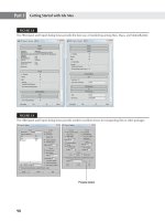
4. In the AutoCAD DWG/DXF Import Options dialog box, make sure the settings are the
same as those shown in Figure 5.20.
Figure 5.20
The AutoCAD
DWG/DXF Import
Options dialog box
showing the set-
tings needed for
this exercise
278
|
CHAPTER 5 worKInG wIth external desIGn data
5. Make sure that the Orient Normals of Adjacent Faces Consistently check box is selected.
This is an important setting because it tells 3ds Max to align all the normals so that they
are pointing outward.
When to Turn Off Orient Normals of Adjacent Faces Consistently
This option should be turned off when you are working with 3D objects created in AutoCAD
Architecture or Revit.
6. Click OK to import the AutoCAD file. The plan appears in the viewport.
The next step is to set up a comfortable view of the model so that you can easily maneuver
within it:
1. Right-click the POV label in the upper-left corner of the viewport, and then select Views
Orthographic or press U. Your view changes to an orthographic projection instead of a
perspective view.
Turn On the Material Color Option
When AutoCAD files are imported, they often appear uniformly as a dull gray color; in rendered
viewports, that may be similar to the viewport background color. A common solution to this situ-
ation is to open the Display tab in the Command panel and select the Material Color radio button
in the Shaded area of the Display Color rollout. If the objects’ material colors don’t have a good
contrast with the background color, try the Object Color option instead.
2. Orbit so your point of view is above and at a 45-degree angle to the plan. Alternatively,
you can click the corner of the ViewCube where the Front, Left, and Top faces intersect.
3. Press the G key to hide the grid for a clearer view.
4. Click the Zoom Extents tool to view the plan so that it looks similar to Figure 5.21.
Figure 5.21
The view so far
IMPortInG autoCad Plans Into 3ds Max desIGn
|
279
Extruding the Walls
The next step is to start extruding the walls. The polyline outlines that you created in AutoCAD
are converted to closed splines in 3ds Max, so you need only to select the splines and apply the
Extrude modifier:
1. Right-click in the viewport and choose Unhide All from the quad menu to unhide the
Layer:MULLION-VERT and Layer:GLASS objects. Layers that are turned off in AutoCAD
are imported as objects that are hidden in 3ds Max.
2. In the Unhide All dialog box that opens, click Yes to unhide the layers these objects are on.
3. Click the Select by Name tool on the Main Toolbar to open the Select from Scene dialog
box. Click the Name column title to sort the object names alphabetically.
4. Select Layer:Wall-3ds-INT, Layer:Wall-3ds-EXT, and Layer:MULLION-VERT from the list,
and then click OK. Remember that you can select multiple, nonconsecutive items from a
list by holding down the Ctrl key while you click.
Combining Objects by Layer
Objects that were combined by layer in the conversion from AutoCAD to 3ds Max have “Layer:”
preceding their AutoCAD layer name.
5. Select the Modify tab in the Command panel, and then select Extrude from the Modifier
List drop-down.
6. In the Parameters rollout, set the Amount input box to 9´6 ˝. The walls and mullions dis-
play in the viewport as shown in Figure 5.22.
In this exercise, you applied the same modifier to three objects: Layer:Wall-3ds-INT, Layer:
Wall-3ds-EXT, and Layer:MULLION-VERT. Whenever you change the Extrude Amount param-
eter for one object, it changes for the others because the Extrude modifier is instanced across the
objects you selected in Step 4, applied to in Step 5. The two sets of walls and the vertical mullions
were segregated in AutoCAD so that you could apply a different material to each of them in 3ds
Max; but because all of these items are the same height, you applied a single modifier to all three
of them.
Figure 5.22
The building after
extruding the
selected objects
280
|
CHAPTER 5 worKInG wIth external desIGn data
If you decide that you need to give each set of walls its own Extrude modifier, you can do
so by clicking one of the walls, selecting the italicized Extrude modifier in the stack, and then
clicking the Make Unique button in the modifier stack, as shown in Figure 5.23.
Italic and Bold Modifiers
Modifiers that appear in italics in the stack are instanced. Modifiers that appear in bold in the stack
are modifiers applied to instanced objects.
Extruding Exterior Wall Headers
Now let’s continue with the exterior door headers and the walls around the windows:
1. Open the Select from Scene dialog box again. Then select Layer:WALL-3ds-EXT-HDR
and Layer:Wall-3ds-SILL.
2. Select Extrude again from the modifier list; then change the Amount value in the
Parameters rollout to 1´6˝.
3. Click the Select and Move tool; then click the Absolute/Offset Mode Transform Type-In
tool next to the coordinate readout so that you are in the Offset mode. You’ll see values
appear in the coordinate readout.
4. In the coordinate readout, change the Z value to 8´0˝. Figure 5.24 shows the door headers
all moved to their positions above the doors.
Figure 5.23
Make the instanced
modifier unique.
Figure 5.24
The headers moved to
an elevation of 8´0˝
IMPortInG autoCad Plans Into 3ds Max desIGn
|
281
You may have noticed that in step 3, the coordinate readout showed values only when you
selected the Offset mode from the Absolute/Offset Mode Transform Type-In tool. This is because
you have more than one object selected. The Absolute mode has no significance for multiple
selections because several objects can have different locations in the scene.
Also, just as with the walls, you used a single instanced Extrude modifier to effect changes to
multiple objects.
Now, take a closer look at the windows. You have the window headers in place, but you also
need a portion of wall to fill in below the windows. You’ll need to copy the window headers and
change their Extrude amount:
1. Select the Layer:WALL-3ds-SILL object. You can use the Select from Scene dialog box
to do this, or you can simply click one of the window headers toward the back of the
building.
2. With the Select and Move tool selected, Shift+click the blue Z-axis arrow of the Transform
gizmo and drag the selected header down to make a clone of the window header object,
roughly placing the copy at ground level.
3. In the Clone Options dialog box, click the Copy radio button to enable it. You can keep
the Layer:WALL-3ds-SILL001 name. Click OK to accept the clone settings.
4. Click the Absolute/Offset Mode Transform Type-In tool to change to the Absolute mode;
then right-click the Z spinner arrows to change the Z value in the coordinate readout to 0.
5. Change the Amount value in the Parameters rollout of the Modify tab to 2´8˝.
Extruding the Mullions
You now have the walls in place. Because you did some prep work in AutoCAD, the work in 3ds
Max went fairly quickly. Even so, you still need to take care of a few items. The horizontal mul-
lions for the curved window need to be created:
1. Use the Zoom Region tool to enlarge your view of the plan near the entrance to the right,
as shown in Figure 5.25.
2. Select the horizontal mullion outline named Layer:MULLION-HORIZ.
3. Select the Extrude modifier in the Modifier List drop-down; then change the Amount
parameter to 2˝.
Figure 5.25
A close-up view of
the entrance and
curved window
282
|
CHAPTER 5 worKInG wIth external desIGn data
4. Choose Edit Clone; then, in the Clone Options dialog box, click Instance, and then click
OK. The clone is now the selected object.
5. Click the Select and Move tool; then change the absolute Z value in the coordinate read-
out to 32˝ or 2´8˝.
6. Choose Edit Clone again; then click OK in the Clone Options dialog box.
7. With the Select and Move tool still selected, change the Z value in the coordinate readout
to 9´4˝. The horizontal mullions for the curved window are now in place.
Creating Interior Wall Headers
You used the Extrude modifier to create the headers for the exterior walls of the Villa. You are
going to use a different method to create the headers for the interior walls.
1. Select Layer:WALL-3ds-INT object.
2. On the Modify tab, select the Extrude modifier and then select the Make Unique button
that was mentioned earlier in the chapter.
3. In the Parameters group of the Extrude modifier, change the number of segments to 2.
4. Right-click the Shading viewport label and select Edged Faces. You should see the extra
segment on your interior walls, as shown in Figure 5.26.
5. With the Layer:WALL-3ds-INT object selected, add an Edit Poly modifier to the stack.
6. Expand the Edit Poly modifier and select the Vertex sub-object mode.
7. Right-click to make the Left viewport active and make a selection window through the
middle of the first floor, as show in Figure 5.27, to select the newly added vertices.
8. In the Mini-Transform Type-In field, change the Z value to 8´.
9. Deselect the vertices you just moved.
10. Change the sub-object mode to Polygon and select the polygon, as shown in Figure 5.28.
Figure 5.26
Extra segments on
the interior walls
IMPortInG autoCad Plans Into 3ds Max desIGn
|
283
11. Using View-Rotate-Sub-Object, arrange the view so you can see the opposite side of the
closet.
12. Ctrl+click and select the polygon opposite the currently selected polygon.
13. On the Graphite Modeling toolbar, go the Polygons tab and select the Bridge command,
as shown in Figure 5.29.
Figure 5.27
Select the center
vertices with a
crossing window.
Figure 5.28
Select the polygon at
the top of the wall.
Figure 5.29
Select the Bridge
command to close
the gap between the
selected polygons.
284
|
CHAPTER 5 worKInG wIth external desIGn data
The Bridge tool connects the selected polygons, removing any interior polygons and welding
the polygons of those faces. See Figure 5.30 to view the bridged polygons.
Using this technique, you need to create the headers over the remaining four interior door
openings on the ground floor of the villa. Once you are done creating the remaining interior
headers, deselect all the polygons and close the sub-object mode of the Edit Poly modifier.
Using the Edit Poly modifier and the Bridge tool allows you to create a model that is well
suited for radiosity or mental ray rendering, or even for sending out for rapid prototyping.
Adding Glass
Let’s continue to model the ground floor of the villa. Next you need to add the glass:
1. Open the Select from Scene dialog box and select Layer:GLASS.
2. Select Extrude from the modifier list; then change the Amount parameter to 9´6˝ and
make sure that the Segments value is set to 1.
The glass appears in only one or two areas. This is because the Glass object is a single spline
and not an outline. You may recall from Chapter 3 that the normals of a surface will render
the surface visible in only one direction. To compensate for this limitation, you can turn the
Layer:GLASS spline into an outline:
1. In the Command panel, select Editable Spline from the modifier stack. The glass disap-
pears in the viewport because you are below the Extrude level in the stack.
2. Right-click in the viewport, and then click the Spline option in the quad menu to enter
that sub-object level for editing.
3. Click the Zoom Extents Selected tool to view the entire Layer:GLASS object.
4. Select Ctrl+A to select all the spline sub-objects of the Layer:GLASS object.
5. Scroll down to the Outline button and input field in the Geometry rollout. Enter 0.2˝↵ for
the Outline value. You won’t see any changes at this viewing distance, but the glass is
now a closed outline instead of a single line. Deselect the spline by clicking Ctrl+D.
Figure 5.30
The bridged poly-
gons form the
header over the
closet opening.
IMPortInG autoCad Plans Into 3ds Max desIGn
|
285
6. Select Editable Spline in the modifier stack to exit the sub-object level.
7. Click Extrude in the modifier stack. The glass appears in all of the appropriate places (see
Figure 5.31) because it now has two surfaces that both have normals that face outward.
8. Save this file as Mysavoye-ground-max.max.
You could have left the glass as a single line. That would make the glass difficult to see in a
shaded viewport, but you could apply a two-sided material to the glass so that it would appear
in a finished rendering. Although a two-sided glass material takes a bit longer to render, the
single-line glass material is a less-complex geometry. This makes the file a bit smaller. For this
reason, if your model contains lots of curved glass, it may make sense to leave the glass as a
single line. Otherwise, you may want to convert all of the glass in your model to outlines. As
you’ve seen here, that’s fairly easy to do in 3ds Max. It takes a bit more work to accomplish the
same results in AutoCAD by using the Boundary tool.
Also, in the previous exercise, you may have noticed that you gave the glass a full height
of 9´6˝, even though, in many cases, the glass only filled a height of 64˝ or less. You can do this
because 3ds Max takes care of the small details of object intersections. In those places where
the glass occurs within a wall, 3ds Max hides most of the glass, and it is displayed only where
it appears in an opening, as shown in Figure 5.32. 3ds Max also takes care of the intersection of
the vertical and horizontal mullions.
Figure 5.31
The Ville Savoye
model after out-
lining the glass
splines
Figure 5.32
The window show-
ing the glass
286
|
CHAPTER 5 worKInG wIth external desIGn data
Radiosity Requires Better Modeling
The creation methods used in these exercises are fine when using the 3ds Max Standard lights
and Scan Line Renderer. If you intend to render your project using radiosity, the modeling must be
cleaner, with no overlapping of faces, for the renderer to create an accurate radiosity solution. Good
clean geometry and models are said to be water-tight, meaning the geometry is completely enclosed.
If you’re using mental ray, it’s also a good idea for the geometry to be non-overlapping.
Creating a Floor with Openings
You’ve seen how the ground floor of the villa can be set up in AutoCAD to make quick work of
the extrusions in 3ds Max. The second floor and rooftop can be done in the same way, but the
floors between the different levels require a slightly different approach.
Both the second floor and the roof surface have openings that need some special attention
when you are setting up to export to 3ds Max:
1. Go back to AutoCAD and open the savoye-second.dwg file. If you don’t have AutoCAD,
skip ahead to the “Importing the Second Floor” section later in this chapter.
2. Click the Layer Properties icon, and in the Layer Properties Manager dialog box, click the
New Layer button. Create a layer named FLOOR-2ND-3ds. Right-click the new layer and
select Set Current from the context menu to make it the current layer.
3. Use the Rectangle or Polyline tool to outline the second floor, as shown in Figure 5.33.
4. Turn off all the layers except FLOOR-2ND-3ds, STAIR, and RAMP; then zoom into the
stair, as shown in Figure 5.34.
Figure 5.33
Outline the
second floor.
Place a rectangle or closed polyline around the perimeter of the second floor plan.
IMPortInG autoCad Plans Into 3ds Max desIGn
|
287
5. Outline the stair with a closed polyline, as shown in Figure 5.34. (In this operation, you’re
drawing the outline of the stair opening in the floor. You will have to toggle between Arc
and Line modes while drawing with the Polyline tool in AutoCAD to complete the out-
line shown in the figure.)
6. Pan over to the ramp. Then draw an outline of the ramp with a closed polyline (you can
use the Rectangle tool), as shown in Figure 5.35.
Figure 5.34
Outline the stair.
Outline the stair with a closed polyline.
Figure 5.35
The outline of the
ramp floor opening
Outline the ramp with a closed polyline or rectangle.
288
|
CHAPTER 5 worKInG wIth external desIGn data
You’ve got all of the additional linework you need to export the floor of the second story to
3ds Max, but you still need to take a few more steps to complete the setup for 3ds Max:
1. Freeze all the layers except the FLOOR-2ND-3ds layer.
Importing Frozen Layers
Frozen layers are automatically excluded from importing into 3ds Max. However, it is possible
to manually select which layers will be included upon import, regardless of their layer state in
AutoCAD (but the workflow is less efficient).
2. Use the Zoom Extents tool to view your work so far (see Figure 5.36). You now have the
outline of the second floor and the two openings through the floor.
3. Choose File (the Application menu in AutoCAD 2009 and newer), and choose Save As to
save your changes to a file named Mysavoye-second-max.dwg.
Basically, you’ve outlined the second floor and its openings with closed polylines. In addi-
tion, you’ve frozen all the layers except the floor outline and openings. This last step lets you
automatically limit the objects that 3ds Max imports to only those items you added to the
AutoCAD file.
im P o r t i n G t h e Se c o n d Fl o o r
The next step is to import your work into 3ds Max:
1. Go back to 3ds Max, click the Application menu, and choose Reset. You can go ahead and
reset the scene because you’ve already saved your work.
2. Click the Application menu and choose Import. Then, in the Select File to Import dialog
box, locate and open the Mysavoye-second-max.dwg file you just saved from AutoCAD. If
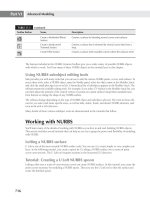
you don’t have AutoCAD, open the savoye-second-max.dwg file.
3. In the AutoCAD DWG/DXF Import Options dialog box, adjust the settings to match
those shown in Figure 5.37.
4. Click the Layers tab in the AutoCAD DWG/DXF Import Options dialog box. Note that
the Skip All Frozen Layers radio button is selected by default. This setting lets you auto-
matically skip importing the layers you froze in AutoCAD.
Figure 5.36
The outline of the
second floor
IMPortInG autoCad Plans Into 3ds Max desIGn
|
289
When you click the Select from List radio button on the Layers tab of the AutoCAD
DWG/DXF Import Options dialog box, you are able to manually check which layers are
imported by toggling the large check mark along the left edge of the list. The layer states
shown in the list (on/off, freeze/thaw, lock/unlock) represent the current state of the
DWG or DXF file and are not functional; they are for your information only.
5. Click OK to import the drawing and close the AutoCAD DWG/DXF Import Options
dialog box.
You now see the outline of the second floor that you created in AutoCAD.
The final step is fairly easy. You only need to extrude the spline, and the openings will
appear automatically:
1. Click the Select Object tool; then click the floor outline.
2. Select the Modify tab in the Command panel; then select Extrude from the Modifier List
drop-down.
3. Set the Amount parameter to 18˝. You now have the floor of the second story, complete
with openings as shown in Figure 5.38.
4. If you’d like, save this file as mysavoye-secondfloor.max for future reference.
When creating an extrusion, 3ds Max automatically subtracts the nested splines, closed
subsplines that are enclosed by other subsplines, of the same spline object. On the second floor,
ramp and stair openings are automatically subtracted from the second floor perimeter.
Figure 5.37
The AutoCAD
DWG/DXF Import
Options dialog box
290
|
CHAPTER 5 worKInG wIth external desIGn data
You were asked to freeze all the layers in AutoCAD except the Max-floor layer. This allowed
you to automatically limit the objects that were imported from AutoCAD into 3ds Max. You can go
back to the AutoCAD file; thaw the wall, header, and other layers; and then freeze the Max-floor
layer. Once you’ve done that, you can import the other second-story elements into a 3ds Max file
and then merge the floor and the walls. On the other hand, you can choose exactly which layers
will be imported on the Layers tab of the updated AutoCAD DWG/DXF Import Options dialog
box. Of course, you can also thaw all the layers and import the entire AutoCAD drawing at once.
But importing parts of an AutoCAD file can help simplify your work and keep it manageable.
Using Building Elevations and Wall Profiles from AutoCAD
In the preceding section, you learned how to convert outlines of a building plan into a floor with
openings. You can employ the same procedures for converting building elevations from AutoCAD to
3ds Max scenes. For example, in AutoCAD you can outline an elevation of the villa using concentric
rectangles for the second floor outline and the windows. You can then import the outlines to 3ds
Max and extrude them, just as you did with the floor. That will give you the exterior walls of the
building that you can rotate into a vertical position. This 3ds Max technique is similar to real-world
tilt-up wall framing construction.
Using this method, you can even include other details such as the window mullions. Once you’ve
done this for all four exterior walls, you can join the walls to form the second floor exterior walls,
complete with window openings and even window detail.
Another great tool for forming building exteriors and interiors is the Loft tool. Sometimes a simple
vertical extrusion won’t be enough for walls. You may be working with a design that uses strong
horizontal elements, such as a wide cornice or exaggerated rustication. You can make quick work
of such detail by using 3ds Max’s Loft tool. Draw the profile of the wall and the building footprint in
AutoCAD. Be sure each of these items is on a separate layer and is made of polylines. You can then
import the AutoCAD file into 3ds Max and use the Loft compound object or the Sweep modifier
to loft the wall profile along the building footprint in a way similar to the exercises in Chapter 7,
“Organizing and Editing Objects.” This is especially helpful if the building footprint contains lots
of curves and corners that would otherwise be difficult to model.
As an alternative, in AutoCAD, you can convert the closed splines of the stair, ramp, and floor into
regions, and then subtract the stair and ramp regions from the floor outline. AutoCAD regions are
converted into 3ds Max mesh surfaces. You then have to extrude the floor with the tools within the
polygon level of the Editable Poly, rather than with the Extrude modifier.
Figure 5.38
The extruded
second floor