Mastering Autodesk 3ds Max Design 2011 phần 9 pps
Bạn đang xem bản rút gọn của tài liệu. Xem và tải ngay bản đầy đủ của tài liệu tại đây (1.96 MB, 97 trang )
usInG lIGhtInG analYsIs
|
751
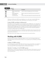
33. Click the Render Production button on the Main Toolbar.
After the rendering has processed, the Rendered Frame Window is updated with the
results from the Lighting Analysis Image Overlay, as shown in Figure 14.83. Another win-
dow, Lighting Analysis Data, also pops up; however, its content is not important.
34. Save your scene as MyMentalRayLightingA.max.
Figure 14.82
The Lighting Anal-
ysis Image Over-
lay render effect
options
Figure 14.83
The Rendered
Frame Window
with the Lighting
Analysis image
overlay
752
|
CHAPTER 14 adVanCed renderInG usInG Mental raY
The values provided by the Lighting Analysis Image Overlay or the Light Meter helper objects
will enable the architect or lighting designer to determine if the combination of natural and arti-
ficial lighting is adequate for the type of environment being studied, or if additional fixtures or
design changes are necessary.
This was a very introductory look at the lighting-analysis tools in 3ds Max Design 2011. There
are a number of very informative white papers on the Autodesk website that go into much greater
detail about configuring and using the 3ds Max Design lighting analysis features. If you are
interested in lighting analysis, you should study those resources thoroughly.
The Bottom Line
Apply final gathering Final gathering is an optional step in calculating global illumination
that can reduce the appearance of unwanted variances or rendering artifacts in the lighting.
Master It Apply final gathering to an exterior view of the Savoye project from Chapter 14,
“Advanced Rendering with mental ray.”
Create a contour rendering Contour renderings display dark strokes along the contours
of a scene’s objects. This is an effect caused by using the mental ray Contour shaders and the
parameters in the Camera Effects rollout.
Master It Using the same techniques covered in this chapter, create a contour rendering
of the interior of a condo scene from Chapter 6, “Creating AEC Objects.”
Use the multi/sub-map material Creating a large number of unique maps to apply to repeti-
tive objects in a scene to add a sense of variation or randomness can take a lot of effort. The
Multi/Sub-Map rollout allows you to create one material with a number of internal variations
that you can apply to objects in your scene to achieve that sense of natural randomness.
Master It Create a 25
× 25 array of 1´ radius spheres, offset 3´ from each other, with a
single material that will randomly change the color of the spheres through the use of the
mental ray Multi/Sub-Map type of map.
Use Skylight global illumination Global illumination can enhance the appeal of a scene
by simulating bounced light. This can include the color bleeding effect where color is trans-
ferred from one surface to another.
Master It Add global illumination to an exterior shot of the Savoye scene from Chapter 8.
Use mr Proxy objects Using mental ray Proxy objects in scenes that require a considerable
number of identical high-poly objects can save you significant file size, system resources, and
render time.
Master It Create and render a 25
× 50 array of mr Proxy teapots using an eight-segment
teapot as the source object.
Use IES files Using Photometric Web distribution files for your photometric lights can
greatly increase the realism and accuracy of your final rendered images.
Master It Using the MyMentalRayIESLighting.max file you saved near the end of the
chapter, change the light distribution type of PhotometricLight001 from Uniform Diffuse
to Photometric Web, and select the cooper.ies file. Then render the scene.
Use lighting analysis Proper accommodation of naturally available light can greatly benefit
a building’s design. Using 3ds Max Design 2011’s lighting-analysis tools can help architects
and lighting designers successfully study how lighting affects a project.
Master It Using the MyMentalRayLightingA.max file you saved in the last exercise, cre-
ate a Light Meter helper object on top of the coffee table, calculate the light meter, and
render the scene, displaying the values of the Light Meter helper on the render.
Chapter 15
Finishing It Off: Atmosphere,
Effects, and Compositing
3ds Max Design 2011 has several features for adding the appearance of objects in your scene
without actually adding any geometry. These features fall into one of two categories: atmospheric
effects and rendering effects. Atmospheric effects are effects that appear to show particulate mat-
ter in the air (such as mist, smoke, or even fire). Rendering effects change the appearance of a
rendered scene by adding objects such as glows and starbursts, but they can also be used to add
hair or fur to an object in the scene. The Hair and Fur effect can be used to simulate grass in a
scene.
You can also render images simulating such real-world camera effects as glare from extremely
bright reflections or light sources and the depth of field created by adjusting the aperture of a
camera lens.
Included with 3ds Max 2011 is Autodesk Composite, a node-based compositing application
that is based on the Autodesk Toxik compositor. Compositing is the process of layering image
elements on top of each other and adjusting how they are blended together to create your final
image. Autodesk Composite features a comprehensive toolkit to maximize your creativity,
including keying, color correction, motion tracking, paint features, full HDR support, depth-of-
field effects, all at resolutions up to 4K film resolution. This chapter cannot go into all the fea-
tures of Autodesk Composite, but it will give you an idea how you can work with your images,
and then you can use the Composite help and learning resources.
In this chapter, you’ll learn to:
Add an atmospheric effect
•u
Add a grass effect using Hair and Fur•u
Add the Glare effect to a rendering•u
Use DOF/Bokeh•u
Create stereo-pair images•u
Composite the stereo pair into an anaglyph image•u
Adding Atmospheric Effects
When a scene is rendered in 3ds Max, the renderer calculates, among other things, the effect of
the scene’s lights on the surfaces of the geometry. By default, the scene is rendered as if the air
surrounding the objects is clear and free of any particulates. In many cases, this is the correct
assumption, and you wouldn’t want to add pollution, fog, or airborne particles to the scene. Yet
754
|
CHAPTER 15 FInIshInG It oFF: atMosPhere, eFFeCts, and CoMPosItInG
sometimes, adding atmosphere effects is necessary to make the scene look more realistic, which
is particularly true when dealing with lighting, fog, and fire.
3ds Max has a set of features, called atmospheres, that can add the appearance of airborne par-
ticles. Real-world lights cast light into their surrounding environment, and you can see the effect
of the lights as both direct and indirect illumination, but you can’t see the actual light rays or
light cone. When the light cone appears to be visible, such as a spotlight at a movie premier or a
car’s headlights on a foggy road, what you’re actually seeing is the light rays diffusing after hit-
ting airborne particles such as dust, smog, or water vapor. The Volume Light atmosphere adds
the light diffusion effect to selected lights in a scene.
Atmospheric effects are also helpful when adding fog to a scene, which can give the impres-
sion of desolation, eeriness, or cold, wet weather conditions. In reality, fog is comprised of an
immeasurable number of minute particles that capture and diffuse light rays. This would be dif-
ficult to calculate and display accurately. You can represent fog in your scenes, including density
changes and color variations, using the Fog atmosphere.
As you can guess, the Fire effect renders as a ball or tendril type of combusting materials that
can change color with distance from the fire’s center. Be aware that the Fire atmosphere, like Fog
and Volume Light, appears only in rendered scenes and not in the viewports. Also note the Fire
effect does not contribute any illumination to the scene.
These effects are designed to work with the scanline renderer, and now that the default ren-
derer is mental ray, you may find that the scanline effects don’t always work correctly. Volume
Light in particular are best reserved for the scanline renderer. To create volume lights in men-
tal ray, you can use a specialized shader called the Parti Volume Photon shader, placed on the
Volume channel of the mental ray Camera Shaders group. The use of that shader is outside the
scope of this book.
Creating a Volume Light
There are many times when you can use a Volume light. Any time a light beam is visible as an
object in a scene, this is a chance to use a volume light. Whether it’s dappled light streaming
through the leaves in a forest, rays casting through a window, or even car headlights or parking
lot streetlamps at night, all of these are a good use of volume lights.
In the following exercise, you’ll add the Volume Light atmosphere to existing lights in a 3ds
Max scene. After adding the atmosphere in the Environment and Effects dialog box, you pick
the lights that will display the effect and then render the scene.
1. Open Savoye15_A.max. This file is similar to the Savoye files you worked with in other
chapters, but with a darker environment and downward-facing spotlights added to the
overhang.
File Load: Gamma Settings
If you get a File Load: Gamma and LUT warning when you open this file, choose Adopt the File’s
Gamma and LUT settings.
2. If it is not already the active viewport, right-click the Camera01 viewport, and then ren-
der the scene. The Rendered Frame Window should look like Figure 15.1 and show the
light pools beneath each spotlight.
addInG atMosPherIC eFFeCts
|
755
Render Camera or Perspective Viewports
The result of atmospheric effects can be seen only in rendered Camera or Perspective viewports
and not in rendered axonometric or orthographic viewports.
3. Press the 8 shortcut key, or choose Rendering Environment to open the Environment
tab of the Environment and Effects dialog box—or you can press the Environments And
Effects button in the Rendered Frame Window.
4. In the Atmosphere rollout, click the Add button to open the Add Atmospheric Effect dia-
log box, as shown in Figure 15.2.
5. Click the Volume Light option and then click OK. Volume Light is added to the Effects
field in the Atmosphere rollout.
Figure 15.1
The first rendering
of the scene
Figure 15.2
The Add Atmo-
spheric Effect
dialog box
756
|
CHAPTER 15 FInIshInG It oFF: atMosPhere, eFFeCts, and CoMPosItInG
6. In the Lights section of the Volume Light Parameters rollout, click the Pick Light button.
At this point, you could select each light in the scene by picking them in the viewports.
Some of the lights aren’t easily selected in the viewports, so you’ll need to use the Pick
Object dialog box.
7. Click the Select by Name button or press the H key to open the Pick Object dialog box
shown in Figure 15.3. Because only lights can be assigned to the Volume Light atmo-
sphere, only lights appear in the list.
8. Highlight all the lights with names that begin with TPhotometricLight and then click
Pick. The names of all the selected lights can be displayed by expanding the drop-down
list in the Lights area.
9. Render the scene again (see Figure 15.4). This time the light cone can be seen from the
source half the distance to the ground.
Figure 15.3
The Pick Object
dialog box used
to select lights
Figure 15.4
The rendered
scene after adding
the Volume Light
effect
addInG atMosPherIC eFFeCts
|
757
Photometric Volume Lights on 64-Bit Systems
If you are using photometric lights with the Volume Light Atmospheric effect in the scanline ren-
derer on a 64-bit system, be aware that there are reports of render artifacts or errors and that the
volumetric effects don’t properly respond to the Noise parameters. We hope this will soon be rem-
edied with a hot fix or a service pack. If you run into this error or any other errors, please submit a
defect report against 3ds Max Design 2011 to Autodesk.
Adjusting the Volume Light Parameters
Like most features in 3ds Max 2011, there are many parameters that can be adjusted to tweak the
appearance of the Volume Light effect. The most notable are those that modify the effect’s den-
sity and color. You can change the color of the volume of light to inject emotion into a scene—for
example, yellow for warmth or blue for moonlight. Use density to make the effect more visible if
needed. Here you will experiment with each of those parameters:
1. In the Volume area of the Volume Light Parameters rollout, click the Fog Color swatch to
open the Color Selector dialog box.
2. Select a pale yellow color (255,255,230 works well) and then click OK to close the Color
Selector.
3. Render the scene again. This time the hue of the lights’ cones is shifted toward yellow.
Not All Instances Are Affected
All the lights selected in this exercise are instances; therefore, adjusting one light’s parameters
adjusts that parameter for all lights. However, just because an instance is a volume light, not all the
instances are volume lights, so each light must be added to the Volume Light effect.
4. Increase the Density value to 8 to increase the amount of light captured by the effect.
Make sure the Exponential option is deselected and then render the scene again. With
Exponential checked, the light’s density falls off exponentially with distance rather than
linearly, as it does when the option is off. Your Rendered Frame Window (RFW) should
look similar to Figure 15.5.
Figure 15.5
The scene after
adjusting the
Density parameter
758
|
CHAPTER 15 FInIshInG It oFF: atMosPhere, eFFeCts, and CoMPosItInG
The Exponential check box is critical to use if you intend to render transparent objects
within the Volume Light or Volume Fog.
You can adjust the Volume Light’s parameters further as you want.
One nice tip to know is that if you put a bitmap in the Projector Map channel, you will get the
bitmap throughout the volume of the light. If you need to accentuate streaks of light in a scene,
this is a helpful technique.
Adding Fog
3ds Max fog comes with two different fog styles: Volume Fog and Fog. With Volume Fog, a
spherical, cylindrical, or box-shaped gizmo called an atmospheric apparatus is added from the
Helpers category on the Create tab. The fog is then created and constrained to the boundaries
of that gizmo. This fog type is good for clouds or when representing a smoke or fog effect that
must be limited to a specific volume.
The other type of fog atmosphere, the one that is used in this exercise, is unlimited in its
extents and fills the area viewed through the camera.
ad d i n G t h e Fo G at m o S P h e r i c eF F e c t
Fog is another atmospheric effect similar to the volume light but not constrained to a helper
object. Let’s try it:
1. If you’ve closed any of the windows, you can reopen the Environment tab of the Environ-
ment and Effects dialog box and then click the Add button in the Atmosphere rollout.
2. In the Add Atmospheric Effect dialog box, double-click the Fog option to select it, and
close the dialog box.
With the Fog option selected in the Effects window, the Fog Parameters rollout replaces
the Volume Light Parameters rollout (see Figure 15.6). If you need to go back and adjust the
Volume Light effect’s parameters, simply select Volume Light in the Effects window.
Figure 15.6
The parameters for
adjusting the fog
addInG atMosPherIC eFFeCts
|
759
3. Render the Camera01 viewport. As you can see in Figure 15.7, the Fog effect starts at the
camera’s viewing plane and increases in density with distance.
4. Although this effect frames the leaves on the tree nicely, in this case you want to just
show some ground fog around the building. In the Fog area of the Fog Parameters roll-
out, click the Layered radio button. The Standard area grays out, and the Layered param-
eters become available.
5. Layered fog has Top and Bottom parameters that set its vertical limits. Set the Top param-
eter to 3´0.0˝ and leave the Bottom set to 0´0.0˝ by clicking and dragging the spinners.
Don’t Obscure the Scene
Make sure the camera is above the top level. If the camera’s Z position is between the Top and Bottom
parameters, then it is within the fog itself, and much of the scene may be obscured.
6. Set the Falloff option to Top, so that the fog gets thinner as it reaches its upper limit.
Render the scene again. Your RFW should look like Figure 15.8. The scene looks better,
but you still need to work on the color and density of the fog.
7. Click the Color swatch in the Fog area, choose a dark gray/green color for the fog, and
then click OK. Here we’re using RGB values 60,100,60.
8. In the Layered group, change the Density values, and render. Do this repeatedly until
you find a good combination of density and color.
Figure 15.7
The rendered scene
after adding the
Fog atmospheric
effect
760
|
CHAPTER 15 FInIshInG It oFF: atMosPhere, eFFeCts, and CoMPosItInG
aS S i G n i n G Pa t c h e S o F oP a c i t Y
Rather than controlling the density with the Density parameter, which results in an even den-
sity throughout the fog, here you’ll use a map to randomly assign patches of opacity. This will
add to the illusion of the fog, because it will not appear as an even computer-generated effect.
Whenever you can add randomness to something, it tends to more naturally mimic reality.
1. Open the Compact Material Editor by clicking the Material Editor button or pressing M
on the keyboard, select an unused sample slot, and then assign a Standard material to
that slot.
2. Expand the Maps rollout and then click the None button next to the Diffuse color channel
to open the Material/Map Browser.
3. Double-click the Noise Map option to select it, and close the Material/Map Browser and
return to the Material Editor.
4. Click the Go to Parent button and then drag the Noise map from the Material Editor’s
Maps rollout to the Environment Opacity Map button, as shown in Figure 15.9.
5. Choose Instance in the Instance (Copy) Map dialog box and then click OK. Because you
chose Instance, any changes made to the map in the Material Editor are reflected in the
scene when it is rendered.
6. Render the scene again. It’s a little better, but the changes in the fog’s density are spaced
too far apart.
7. Click the Diffuse Color map button in the Maps rollout to get to the material’s noise map.
8. In the Noise Parameters rollout, set the Size value to 10 and the Noise type to Fractal to
make the noise effect smaller and sharper. Then render the scene. Your RFW should look
similar to Figure 15.10.
9. Close the Material Editor.
Figure 15.8
The rendered
scene after switch-
ing to layered fog
and adjusting the
falloff
addInG atMosPherIC eFFeCts
|
761
Control the Fog’s Color with a Map
Instead of using the Color swatch in the fog area to control the fog color, you can use a map. Similar
to the way that you assigned a map to the Environment Opacity Map option, you could assign one to
the Environment Color Map option as well. The fog would then get its colors from the map’s colors,
whether the map is a bitmap or a procedural map.
Figure 15.9
Dragging a map
from the Material
Editor to the fog
parameters
…to here.
Drag from here…
Figure 15.10
The scene after
adding a Noise map
to control the opac-
ity of the fog
762
|
CHAPTER 15 FInIshInG It oFF: atMosPhere, eFFeCts, and CoMPosItInG
he l P i n G Yo u r Fo G in t e r a c t w i t h t h e ho r i Z o n
The last feature that you want to address is how the fog interacts at the horizon. If you look in
the Camera01 viewport, you’ll see a black line in the background that sits just above the top of the
land on which the building sits. This is the horizon line, and its visibility is controlled with the
Show Horizon option in the camera’s Parameters rollout. You can add noise at the horizon to
break up the regularity of the computer-generated effect.
1. In the Layered area of the Fog Parameters rollout, select the Horizon Noise option.
2. Reduce the Size parameter to 10, and then change the Angle value to 6. The Angle value
determines how many degrees below the horizon the horizon noise begins.
3. Render the scene one more time, and you should see the fog at the horizon line now
broken up, as shown in Figure 15.11.
4. Save your file as MySavoye15_A.max
Adding a Fire Effect
Like the Volume Fog effect mentioned earlier, the Fire Effect atmospheric effect requires a gizmo
to contain it. You can control whether the flames are reaching upward with tendrils or whether
the flame is formed into a ball. Unlike real fire, the Fire effect does not cast any light into the
scene and is almost always accompanied by a light. In this section, you’ll create a Fire effect,
which you’ll add to a fire pit next to the building.
1. Open Savoye15_B.max from this book’s accompanying web page.
2. Click the Helpers button under the Create panel, expand the drop-down list, and select
Atmospheric Apparatus.
3. Click the SphereGizmo button. In the Top viewport, click near the center of the fire pit at
the lower-left corner of the villa and drag the gizmo until it is about the size of the center
of the fire pit (see Figure 15.12).
Figure 15.11
Horizon Noise con-
trols the appear-
ance of the fog at
the horizon.
addInG atMosPherIC eFFeCts
|
763
4. Click the Modify tab of the Command panel and then select the Hemisphere option for
the Sphere gizmo.
5. In the Front viewport, move the gizmo upward until its flat bottom is inside the fire pit.
6. Set Radius to 3´0.0˝.
Changing the Fire’s Shape
Gizmos are subject to the same transforms that other objects are, so you can use the Scale transform
to change the sphere shape to more of a capsule shape.
7. With the gizmo selected, click Select and Non-uniform Scale and then drag the Z-axis
handle upward, as shown in Figure 15.13, to nonuniformly scale the gizmo along the
Z-axis only.
8. In the Modify panel, on the Atmospheres & Effects rollout, click the Add button.
Figure 15.12
Creating the gizmo
in the Top viewport
Figure 15.13
Scale the atmo-
spheric apparatus
along the Z-axis.
764
|
CHAPTER 15 FInIshInG It oFF: atMosPhere, eFFeCts, and CoMPosItInG
Turning Off an Atmospheric Effect
You can turn off any atmospheric effect by selecting it and deselecting the Active option in the
Atmosphere rollout. You can force 3ds Max to not render any atmospheric effects by opening the
Render Setup dialog box, selecting the Common tab, opening the Common Parameters rollout,
going to the Options section, and deselecting the Atmospherics option.
9. In the Add Atmospheric Effect dialog box, double-click the Fire Effect option to select it,
and close the dialog box.
10. Open the Environment and Effects dialog box; with the Fire Effect option selected in the
Atmosphere window, the Fire Effect Parameters rollout (see Figure 15.14) appears below
the Effects window.
11. Render the scene; your RFW should look like Figure 15.15.
Figure 15.14
The Fire Effect
Parameters rollout
Figure 15.15
The rendered scene
after adding the
Fire effect
addInG atMosPherIC eFFeCts
|
765
12. In the Fire Effect Parameters rollout’s Shape section, change Flame Type to Tendril and
increase the Stretch value to 3. Stretch elongates the tendrils along the Z-axis.
13. In the Characteristics section, change Flame Size to 5 and Flame Detail to 5 to give the
effect well-defined tendrils. Finally, reduce Density to 10.
14. Render the seen again to see the result of your parameter changes. Your rendering should
look similar to Figure 15.16.
ad d i n G a li G h t t o t h e Sc e n e
As mentioned earlier, the Fire effect does not add illumination to the scene. In the real world, the
light from the flames would spill onto the building and ground. You therefore need to add a light
to complete the illusion. To do this, just follow these steps:
1. From the Command panel, choose Create Lights Photometric Free Light and then
click near the Atmospheric Apparatus gizmo in the Top viewport.
2. Click the Align button on the Main Toolbar, and align the center of the light with the cen-
ter of the gizmo.
3. Click the Modify tab. In the Intensity/Color/Attenuation rollout, click the Kelvin option,
and then click the Filter Color swatch.
4. In the Color Selector that opens, choose a bright yellow or orange color to set the light
color.
5. In the Intensity area, set the Candelas (cd) value to 3000 to double the light’s intensity.
6. In the Colors section of the Environment and Effects dialog box, click the red Outer Color
swatch and increase the redness by changing the RGB values to 227,12,12. Click OK.
7. On the Shadow Map Params rollout, change the Bias to 0.01 and the Size to 1024.
Figure 15.16
The Fire effect
after adjusting the
parameters
766
|
CHAPTER 15 FInIshInG It oFF: atMosPhere, eFFeCts, and CoMPosItInG
8. In the Logarithmic Exposure Control Parameters rollout, reduce the Brightness value to
50 to darken the scene a bit and make the fire pop.
9. Render the scene; your RFW should look similar to Figure 15.17.
an i m a t i n G t h e Sc e n e
Fires are not static; they are continuously churning and moving elements. To sell this effect in
an animation, follow these steps to animate both the fire and the light:
1. Move the Time slider to frame 100 and then click the Auto Key button.
2. In the Motion area of the Fire Effect Parameters rollout, set the Phase value to 12 and the
Drift value to 20.
3. Select the light in the fire pit and change the Filter color to a brighter yellow red and the
intensity to 4000 cd.
4. Move the Time slider to 50, and then set the filter color to a light red and the intensity to
2700 cd.
5. Select the gizmo and then add a Noise modifier to it. In the Strength area, change the X,
Y, and Z values to approximately 35´, -30´, and 4´, respectively.
6. Move the Time slider back to frame 100, and then change the X, Y, and Z values so that
the Noise modifier distorts the gizmo differently over time.
7. Click the Auto Key button to turn it off.
8. Open the Render Setup dialog box and choose Active Time Segment in the Output area.
9. Save your file as MySavoye15_B.max.
It’s always prudent to save your file before you begin a render. If the computer crashes
during a render, you haven’t lost any work on your Max file this way.
Figure 15.17
The rendered scene
after adding a light
usInG haIr and Fur to add Grass
|
767
10. Click Files in the Render Output section, give the file a name, choose AVI or MOV as the
file type, make any setup changes you prefer, and then click the Render button.
Generally, rendering directly to a movie format is not a smart way to work. When you
are rendering a large number of frames, you will lose the entire movie if 3ds Max or your
system crashes. Also, rendering directly to a movie file bakes the compression into the
file. You should render to a sequence of uncompressed frames (then if the system crashes,
you haven’t lost too much time and can restart the rendering at the last completed frame)
and then use the Video Post tool in 3ds Max 2011 or the Composite application to generate
a movie file from the sequentially numbered frames. In this case, you’ll take a chance and
render directly to a movie. This could take some time, so you might want to take a short
break here.
11. Play your rendered animation in Windows Media Player or Apple QuickTime—or you
can choose View Image File from the Rendering menu, and this will automatically launch
the correct player from within 3ds Max.
The fire churns well, and the colors change nicely. You should consider taking this exercise
a little further by animating the position of the light and the radius of the gizmo. You could
even use soft selection to put a noise modifier on the branches of the tree and animate the noise
modifier similar to the one on the gizmo to give the appearance of the tree swaying in a gentle
breeze.
Using Hair and Fur to Add Grass
3ds Max has several nonatmospheric effects that are added through the Effects tab of the
Environment and Effects dialog box. Although most of these are rendering effects, such as
Motion Blur, Film Grain, and Lens effects (stars, glows, lens flares, and so on), there is also the
Hair and Fur effect. Although there isn’t much call for hair or fur in most architectural render-
ings, the effect can also be used to create convincing grass and other ground cover. Like the
atmospheric effects, the Hair and Fur effect can be rendered only in Perspective and Camera
viewports. Rendered hair or fur is a combination of applying the Hair and Fur modifier to an
object or spline in your scene and applying the Hair and Fur render effect, which is automati-
cally added to the Environment and Effects dialog box when you apply the modifier.
1. Open Savoye15_C.max.
This file is similar to the Savoye files you worked with earlier in this chapter, but with a
lighter environment, no atmospheric effects, and the Ground object was replaced with a
plane that has been edited so that there are no faces beneath the building. The Hair and
Fur effect is assigned to an entire object and can’t have only a portion of an object passed
up to it in the modifier stack. The assigned renderer is mental ray.
2. Select the ground object, the object named Plane01.
3. Apply the Hair and Fur (WSM) world space modifier to the ground. A small percentage
of the actual number of hairs appears in the viewports. As you can see in Figure 15.18, the
hairs are much too long.
768
|
CHAPTER 15 FInIshInG It oFF: atMosPhere, eFFeCts, and CoMPosItInG
4. Open the Effects tab (not the Environment tab that you’ve used so far) of the Environ-
ment and Effects dialog box, and you’ll see that the Hair and Fur effect was automatically
added to the Effects window.
5. Select the Hair and Fur effect. The Hair and Fur rollout appears at the bottom of the
Effects tab.
6. In the Hair Rendering Options section of the Hair and Fur rollout, make sure the mr Prim
option is selected from the Hairs drop-down list. This option designates a procedural
mental ray shader as the engine that renders the hairs.
Adjusting the Hair and Fur Parameters
The grass looks like huge, rectangular stalks sitting on the ground plane, and the color needs
some work as well. In this section, you’ll size the grass better and change the color.
1. With the Plane01 object selected, expand the Hair and Fur (WSM) General Parameters
rollout on the Modify tab.
2. Set Scale to 1.75 to decrease the size of the hair strands, or in this case, grass blades. Set
Cut Length to 75.
3. Set Rand. Scale to 30 so that each blade’s length is not exactly the same and can vary 15
percent above or below the standard length.
4. Decrease the Hair Segments value to 3. The grass isn’t seen up close enough to warrant
the extra detail given by the larger number of segments.
Hair and Fur gets its color from the Material Parameters rollout and not the Material
Editor. You can control the color at the base of the blade (Root Color) and the tip (Tip
Color) and allow a variance between the blades.
5. Expand the Material Parameters rollout.
6. Click the small gray button to the right of the Root Color swatch. This is how you assign a
map, rather than a color, as the source for the grass color.
Figure 15.18
The hairs as they
first appear in the
viewport
usInG haIr and Fur to add Grass
|
769
7. In the Material/Map Browser that opens, choose the Scene group to display only the
maps that exist in the current scene.
8. Double-click the Surface Shader: Map # 8 (GRASS2.jpg) map.
9. Choose the Instance radio button in the Instance or Copy? dialog box and then click OK.
A capital M appears on the button to indicate that a map is controlling the color.
10. Click the Tip Color swatch and then in the Color Selector assign a light green color simi-
lar to 70,105,35. The blades will now transition from the map’s color at the root to the
assigned tip color.
Mutants Are Allowed
If you want to have random hairs that possess their own color, much different than the Root and
Tip Color values, assign a color to the Mutant Color swatch and increase the Mutant % to more
than 0.0.
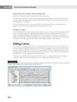
11. Render the Camera01 viewport. The scene is not quite where we want it (see Figure 15.19).
Rening the Ground with the Hair and Fur Parameters
Two problems exist in the scene: first, a massive number of grass blades are needed to sell the
illusion of a lawn, and second, the ground object is very large. In this exercise, you’ll start by
deleting and reconfiguring the ground plane to make it smaller and then finish by refining the
Hair and Fur parameters.
1. Make the Top viewport the only viewport, and then zoom out so that you can see the
entire scene.
Figure 15.19
The rendered scene
after changing
several Hair and
Fur parameters
770
|
CHAPTER 15 FInIshInG It oFF: atMosPhere, eFFeCts, and CoMPosItInG
2. Turn off the UVW Mapping and Hair and Fur (WSM) modifiers and then click the Edit
Poly modifier. If a Warning dialog box appears, click the Hold/Yes button.
3. To access the Polygon sub-object level, press 4 on the keyboard, and then select the poly-
gons shown in Figure 15.20 and delete them.
4. Access the Vertex sub-object level by pressing 1 on the keyboard. Move the perimeter ver-
tices to adjust the ground plane as shown in Figure 15.21. The smaller-sized ground plane
will display the same number of rendered grass blades, but they will be much denser.
5. Exit the Vertex sub-object level and then turn the other modifiers back on. It’s important
to make sure you’ve selected the Edit Poly object level—otherwise, you will be passing an
empty selection set to the Hair and Fur modifier.
6. Select the Hair and Fur (WSM) modifier and then access the General Parameters rollout.
7. Increase the Hair Count to 300,000. This may seem like a large number, but it’s not
uncommon for this value to be set to 5 to 10 million.
8. Reduce Scale to 0.5 and Root Thick to 0.5. These parameters shorten the blades even more
and decrease the thickness at the base.
Figure 15.20
Delete the selected
polygons.
Figure 15.21
Move the vertices
to achieve this
shape.
usInG Glare
|
771
9. Render the Camera01 viewport one more time. Note that this could take a very long
time, depending on your computer’s processor and memory. This rendering calculation
might take several hours using mental ray. Your completed grass should look similar to
Figure 15.22.
10. Save your file as My_Savoye15_C.max.
Using Glare
Earlier in this chapter you rendered a Volume Light effect and read about the Parti Volume
Photon shader, which can re-create the dispersion of light against particulates in a medium.
Other effects can also be simulated with the mental ray renderer in 3ds Max.
Assigning the Glare Output Shader
In a physical camera, be it film or digital, extremely bright lights or reflections that are viewed
through the lens can reflect and refract on the film emulsion or on the surface of the digital sen-
sor. This effect is called glare.
1. Open the Savoye15_D.max file from this book’s accompanying web page.
This is similar to the Villa Savoye files that you worked with earlier in this chapter, but
with some additional detail around the villa and some spheres of various sizes and with
different materials placed out in the grass.
2. Right-click the Camera.View.3DFRONT viewport to select it.
3. Click the Render Production button to have mental ray render the viewport. The
Rendered Frame Window should look like Figure 15.23.
Figure 15.22
The final rendering
after adjusting the
ground plane and
modifier parameters
772
|
CHAPTER 15 FInIshInG It oFF: atMosPhere, eFFeCts, and CoMPosItInG
Figure 15.23
The rendered view
4. Right-click in the Rendered Frame Window. The mouse cursor turns into an eyedropper,
and you are presented with the pixel data dialog box that tells you about the pixel that
the eyedropper is sampling. Move the eyedropper over the bright portion of the large
white sphere and look at the numbers in the pixel data floating dialog box. The dialog box
should look like Figure 15.24.
Notice that the RGB values for that pixel in the Real column are greater than 1.0. This is
because the Rendered Frame Window is set to 32 Bits per Pixel and is displaying floating-
point values of the High Dynamic Range rendering.
5. Right-click again in the Rendered Frame Window, and put the eyedropper over the reflec-
tion of the sun on the brass sphere (it’s the middle one). You might have to use the scroll
wheel on your mouse to zoom into the image to accurately pick the hot spot.
This time the RGB values are much higher; they almost reach 3.0. In a real film or digital
camera, when extremely intense light hits the film or the sensor, the light can disperse
through the celluloid or reflect off the surface of the sensor, creating a halo around the
bright areas. You can simulate this effect in mental ray with the Glare shader.
You will re-create this effect now.
Figure 15.24
The pixel data
dialog box
usInG Glare
|
773
6. Click the Render Setup button on the Main Toolbar. Go to the Renderer tab and
scroll down to the Camera Shaders group of the Camera Effects rollout, as shown in
Figure 15.25.
7. Click the check box in front of the button labeled DefaultOutputShader (Glare) to enable
that shader channel.
8. Open the Slate Material Editor.
9. Click and drag the DefaultOutputShader (Glare) button to the Active View1 Window of
the Slate Material Editor, select Instance, and click OK on the Instance (Copy) Map dia-
log box.
10. Click the plus symbol next to Additional Params on the DefaultOutputShader (Glare)
node, as shown in Figure 15.26.
11. Click the up arrow next to Quality and set it to 3.
12. Click the up arrow next to Spread and change it to 3 as well.
13. Click the 500 next to Resolution For, and change the value to 640, the horizontal resolu-
tion that you have been rendering the scene at.
Figure 15.25
The Camera Shad-
ers group
Figure 15.26
Click to display
the additional
parameters.
4. Right-click in the Rendered Frame Window. The mouse cursor turns into an eyedropper,
and you are presented with the pixel data dialog box that tells you about the pixel that
the eyedropper is sampling. Move the eyedropper over the bright portion of the large
white sphere and look at the numbers in the pixel data floating dialog box. The dialog box
should look like Figure 15.24.
Notice that the RGB values for that pixel in the Real column are greater than 1.0. This is
because the Rendered Frame Window is set to 32 Bits per Pixel and is displaying floating-
point values of the High Dynamic Range rendering.
5. Right-click again in the Rendered Frame Window, and put the eyedropper over the reflec-
tion of the sun on the brass sphere (it’s the middle one). You might have to use the scroll
wheel on your mouse to zoom into the image to accurately pick the hot spot.
This time the RGB values are much higher; they almost reach 3.0. In a real film or digital
camera, when extremely intense light hits the film or the sensor, the light can disperse
through the celluloid or reflect off the surface of the sensor, creating a halo around the
bright areas. You can simulate this effect in mental ray with the Glare shader.
You will re-create this effect now.
774
|
CHAPTER 15 FInIshInG It oFF: atMosPhere, eFFeCts, and CoMPosItInG
14. Click the Render button to see the image with the glare applied. You will see the effect on
the three spheres, as shown in Figure 15.27.
When you are rendering outdoor scenes using the mr Sun and Sky, be careful when using
the Glare shader. The Sky itself is so intense that often it will be affected by the shader as
well, and there can be an especially bright section near the horizon.
15. Save your scene as My_Savoye15_D.max.
Using Depth of Field
Another in camera effect that you can simulate with the mental ray renderer is depth of field.
Depth of field (DoF) is created by light rays hitting the image plane from many different direc-
tions when the aperture in the lens is wide open. When the aperture is small, only parallel rays
of light can hit the image plane and the depth of focus is not as pronounced.
1. Open the DepthofField.max file from the book’s website.
2. Right-click in the Camera002_CoffeeTable viewport to make it active.
3. Click the Render Production button on the Main Toolbar to render the camera view. The
Rendered Frame Window should look like Figure 15.28.
Figure 15.27
Glare on the three
spheres
Figure 15.28
The rendered view
usInG Glare
|
775
4. Click the Render Setup button on the Main Toolbar and click the Renderer tab.
5. Scroll down to the Camera Effects rollout and click the button labeled None next to the
checked Lens shader.
6. On the Material/Map Browser, expand the Maps mental ray group if it isn’t already,
and select Depth of Field/Bokeh, as shown in Figure 15.29. Then click OK.
Next, you’ll adjust the depth of field:
1. Open the Slate Material Editor.
2. Drag the Depth of Field/Bokeh shader to the Active View1 Window of the Slate Material
Editor.
3. Double-click the Depth of Field/Bokeh node to access the settings in the Parameter
Editor.
4. Set the Focus Plane to 5´10˝.
Radius of Confusion
The radius of confusion is a physical quality of a camera system involving the lens and the focal
distance and is extremely mathematical and difficult to describe. If you are interested in reading
about this concept and aren’t scared off by extreme math, there are a number of wiki articles about
the radius or circle of confusion that you can find online.
5. Change Blade Count to 7.
6. Save the scene as My_DepthofField.max
7. Click the Render button on the Render Setup dialog box. When the Missing Map Files
dialog box opens, click Continue. The finished rendering in the Rendered Frame Window
should look like Figure 15.30.
Figure 15.29
Select Depth of
Field/Bokeh.