General ultrasound In the critically ill - part 6 pot
Bạn đang xem bản rút gọn của tài liệu. Xem và tải ngay bản đầy đủ của tài liệu tại đây (1.77 MB, 20 trang )
References
95
25.
Couson F, Bounameaux C, Didier D, Geiser D,
Meyerovitz MF, Schmitt HE, Schneider PA (1993)
Influence of variability of interpretation of con-
trast venography for screening of postoperative
deep venous thrombosis on the results of the throm-
boprophylactic study. Thromb Haemost 70:573-
575
26.
Hull
RD,
Hirsh
J,
Carter
CJ,
Jay
RM,
Dodd
PE,
Ockel-
ford PA, Coates G, Gill GJ, Turpie AG, Doyle DJ,
BuUer HR, Raskob GE (1983) Pulmonary angio-
graphy, ventilation lung scanning and venography
for clinically suspected pulmonary embolism with
abnormal perfusion lung scan. Ann Intern Med
98:891-899
CHAPTER
15
Pleural Effusion and Introduction to the Lung Ultrasound
Technique
The pleural cavity, a basic target in the critically ill
patient,
is
highly accessible to ultrasound. It
is
pos-
sible to accurately diagnose pleural effusion, to
specify its nature, and to safely analyze it through
direct puncture, even in a ventilated patient.
Traditionally, thoracic ultrasound is limited to
the exploration of pleural effusion, with variable
penetration.
We
will see in the following chapters
that this vision can be broadened. If the indication
of pleural effusion alone is considered, and even
though it was described long ago
[1],
this applica-
tion is not exploited to its fullest in all institutions.
A lack of solid data may explain this paradoxical
situation.
We will use this chapter to introduce the basic
notions of lung ultrasound.
Basic Technique of Pleuropulmonary
Ultrasonography
Lung
ultrasound
is a
dynamic
approach.
It requires
precise definition of the patient's situation with
respect to the earth-sky axis. Fluids want to
descend, gases to rise. We can thus separate lung
disorders into dependent disorders, which include
pleural fluid effusion and a majority of alveolar
consolidations, and nondependent disorders, which
include pneumothorax and generally interstitial
syndrome.
The critically ill patient can be examined supine
or sometimes laterally, rarely in an armchair,
almost never in the prone position. Dependent
lesions become nondependent if the position of
the patient has changed. These features must be
precisely defined during an examination, even at
the price of redundancy. For
instance,
we
describe
a »posterior dependent pleural effusion in
a
supine
patient.«
The lung surface is very large (about 1,500 cm^).
The lung is the most voluminous organ, and the
question is raised of where to apply the
probe.
The
answer could be at the same places as the stetho-
scope, which
is
perfectly realistic. In
some
instances,
one stroke of a stethoscope answers the cUnical
question. For more detail, like the abdomen, the
lung surface can be divided into nine well-defined
areas:
1.
The anterior zone (Fig. 15.1) is limited by the
sternum, the clavicle, the anterior axillary line
and the diaphragm. This zone can be divided
into upper and lower halves, or again into four
quadrants like the breast.
2.
The lateral zone (Fig 15.1) extends from the
anterior to the posterior axillary
lines.
The pos-
terior limit, at the posterior axillary
line,
is thus
explored with the probe at bed leveHn a supine
patient. The bed prevents the probe from
exploring more posterior areas.
3.
The posterior zone (Fig. 15.2) extends from the
posterior axillary line to the rachis. It can be
divided into upper, middle and lower thirds,
which roughly correspond to the dorsal seg-
ment of the upper
lobe,
the Fowler lobe and the
posterobasal segment of
the
lower lobe.
Fig.
15.1.
The individualizable areas of
thoracic
ultraso-
nography. Areas
1,
2,
3,
4:
superior-external quadrant,
etc.
of the anterior aspect. Areas 5 and 6: upper and
lower
areas
of
the
lateral
aspect.
LAA(P)y
axillary
anteri-
or (posterior) line
Basic
Technique of Pleuropulmonary Ultrasonography 97
Fig.
15.2.
Upper (5), middle (M) and lower (I) areas of
the posterior pulmonary aspect. The patient can be in
the ventral decubitus, but is usually in the lateral posi-
tion for this analysis, and can even remain in the dorsal
decubitus if the probe is short (see Fig. 15.3)
Fig.
15.3.
On the left figure,
the
probe explores the lateral
zone up to bed level. The bed prevents the probe from
going further. On the right
figure,
the back of the patient
has been sHghtly raised (the lateralization maneuver),
and the probe then reaches precious centimeters of
exploration. Minimal effusion or very posterior conso-
lidation can be diagnosed. Note that the probe, with
respect to the horizon, is pointed toward the sky
In practice, stages of investigation can be defined:
• Stage 1. Supine analysis of the anterior wall
alone defines investigation stage l.This approach
detects or rules out pneumothorax and inter-
stitial syndrome in a few instants.
• Stage 2. Addition of the lateral zone to the
anterior zone immediately detects clinically rel-
evant pleural effusions and alveolar consolida-
tions.
We sometimes speak of pleural effusion
detectable when the bed prevents further pro-
gression of the probe.
• Stage
3.
To
examine at least a portion of the pos-
terior zone in a supine patient, the patient is
slightly rotated, by taking the arm to the con-
tralateral shoulder (Fig. 15.3). This slight rota-
tion allows a short probe to be inserted as far as
possible and explore a few centimeters of the
posterior zone. The probe should point to the
sky. This lateralization maneuver defines stage
3.
The small pleural effusions and alveolar
consolidations that were not detected by the
previous maneuvers become accessible. Sub-
posterior effusion implies that the patient
remained supine and underwent the lateraliza-
tion maneuver.
• Stage 4. This stage implies substantial analysis,
including analysis of the posterior zones after
positioning the patient in the lateral decubitus.
An analysis of the apex will be added, by apply-
ing the probe at the supraclavicular fossa in a
Fig.
15.4.
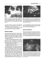
Pleural effusion as it appears during a transab-
dominal approach, through the liver
(L),
in
a
transversal
scan. This traditional approach does not provide a defi-
nite diagnosis with certain lower-lobe consolidations
and also does not allow ultrasound-guided thoracente-
sis.
Note that the effusion goes posterior to the inferior
vena cava (V), a feature that distinguishes, if necessary,
pleural from peritoneal effusion
supine patient. Stage 4 offers more information,
which makes ultrasound nearly as competitive
as CT, as will be proven [2].
The intercostal spaces are always directly explored.
We never use the traditional subcostal approach,
which appears insufficiently informative, not to say
sometimes misleading (Fig. 15.4). Our small micro-
convex probe is perfect for the intercostal approach.
The practice of longitudinal scans makes it pos-
sible to always keep the ribs under visual control, a
98 Chapter 15 Pleural Effusion and Introduction
to
the
Lung
Ultrasound Technique
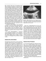
Fig.
15.5.
Substantial pleural effusion by the intercostal
route, longitudinal scan of the right base. Principal fea-
tures are the anechoic pattern of the effusion, which just
evokes the transudate. The lower lobe
(LL)
is swimming
within the pleural effusion in real-time. The hemidia-
phragm, located just above the liver
(L),
moves in rhythm
with respiration, its course can be clearly measured.
The posterior shadow of
a
rib
(asterisks)
hides
a
portion
of the alveolar consolidation. Note that the pleural effu-
sion and this posterior shadow are both anechoic. This
anechoic area is real for the former and artifactual for
the latter
basic landmark (the bat sign; see Fig. 16.1,p 105) in
order to avoid serious mistakes. The next step is to
locate the thorax: one must therefore locate the
diaphragm, which can be visible through a pleural
effusion (Fig. 15.5) or not visible (see
Fig.
4.9,
p 22).
The diaphragm is usually recognized: a large
hyperechoic concave structure which descends -
in principle - at expiration. Everything above (i.e.,
at the left of the image) is thoracic, everything
under is abdominal. This precaution avoids confu-
sion between pleural and peritoneal effusions, and
also between alveolar consolidation and normal
abdominal structures. The diaphragm, in a supine
patient, is located most often at the mamillary line
or a few centimeters below.
The following step, fine analysis of the pleural
layers, will be detailed in Chap. 16.
Normal Aspect of the Pleura
The pleural cavity is normally virtual. Distinguish-
ing between parietal and visceral layers is not pos-
sible using a
5-MHz
probe, but this limitation is
without clinical relevance. At the pleural line (which
will be described in more detail in Chap. 16), the
only visible elements are lung sliding and air arti-
facts,
which belong to the group of lung
signs,
to be
Fig.
15.6.
This minimal effusion follows the laws of grav-
ity. It is impossible to detect since the probe points
downward to the center of the earth, regardless of
whether the patient is studied at bed level (top figure) or
in the lateral decubitus {bottom figure)
studied in Chaps. 16 and 17. Figures 16.1-16.3,
pp 105-106, and 17.6-17.9, pp 120, all correspond
to normally joined pleural layers.
Positive Diagnosis of Pleural Effusion
The first ultrasound description of pleural effu-
sion seems to have been made in 1967 [1]. We
should immediately point out a basic detail: pleu-
ral effusion collects in dependent areas. Any free
pleural effusion will therefore be in contact with
the bed in a supine patient. This zone will not be
easy to approach. Rotating the patient in the later-
al decubitus will not be entirely satisfactory, since
the effusion will subsequently move (Fig. 15.6).
The main key to detecting the effusion is to give a
maximal skyward direction to the probe, which is
inserted to its maximum at the (supine) patient's
back, thus using the lateralization maneuver and
pointing as much as possible toward the sky.
Therefore, a long probe will be a major hindrance
Positive
Diagnosis
of
Pleural
Effusion 99
Fig.
15.7. This scan is not very different from that of
Fig.
15.5.
However, the effusion is less voluminous and
septations are visible. The lower lobe (LL) is entirely-
consolidated. In this patient with purulent pleurisy, in
real-time
the
hemidiaphragm
was
completely motionless
to this maneuver, and to the practice of lung ultra-
sonography in the critically ill.
In our experience, the diagnosis of pleural effu-
sion depends on static and above all dynamic
signs.
The main static sign is the detection of a
dependent collection, limited downward by the
diaphragm, superficially by a regular border, the
parietal pleural layer, always located at the pleural
Une,
and deeply by another regular border, the vis-
ceral pleural layer (Fig. 15.7). The more reliable
sign is in our experience dynamic: the deep bor-
der, which indicates the visceral pleural layer.
Fig.
15.8.
The sinusoid
sign.
In
a
longitudinal scan of the
base,
this collection's thickness (E) varies in rhythm
with the respiratory cycle. The deeper border (black
arrows) moves toward the chest wall, thus shaping a
sinusoid, whereas the superficial border
(black
arrows),
which designates the pleural line, is motionless. The
sinusoid sign is specific to pleural effusion
Fig.
15.9.
Bedside radiography performed in a patient
with acute respiratory failure. The initial diagnosis was
cardiogenic pulmonary edema. Both cul-de-sacs are
free,
thus indicating absence of pleural effusion. How-
ever, not only pleural effusion was proven using ultra-
sound, but 20 cc of effusion were safely withdrawn in
this mechanically ventilated patient. Immediate analysis
of the fluid indicated exudate, a finding which modified
the immediate management (definitive diagnosis was
infectious pneumonia)
moves toward the parietal pleura at inspiration
(Fig. 15.8). This sign, which could be called the
sign of the respiratory interpleural variation, or
the sinusoid sign, is mandatory for an accurate
diagnosis of pleural effusion. Its specificity is 97%
[3].
The visuaUzation of a floating and freely rip-
pling lung within the collection, like a jellyfish (the
jellyfish sign), is a variant of this sign (Fig. 15.5).
The sinusoid sign affords two advantages: first, it is
specific to pleural effusion. Second, it indicates low
viscosity, as we will see below. In very viscous
effusion or septate effusion, the sinusoid sign is
not present. Note that a complex echostructure is a
criterion of fluid collection [4].
Ultrasound provides many advantages com-
pared to the physical examination (we rarely hear
a pleuritic murmur or pleural rubbing in critically
ill patients), but above all compared to radio-
graphy (Fig. 15.9). Ultrasound is recognized as
the choice method to detect pleural effusion in a
supine patient [5]. It usually detects the effusion
that is occulted in radiography [4]. Up to 500 ml
can be missed with bedside radiography
[6,7].
We
will see that ultrasound can diagnose and even
safely tap pleural effusion that is radio-occult, even
100 Chapter 15 Pleural Effusion and Introduction to the Lung Ultrasound Technique
Fig.
15.10.
Minimal pleural effusion, longitudinal scan
of the
base,
patient slightly rotated to the contralateral
side.
In
this
scan,
the
distance between skin and parietal
pleura
(16
mm) can be accurately
measured.
The
inter-
pleural inspiratory distance is
7 mm, a
finding that dis-
courages a diagnostic
tap. The
air artifacts posterior to
the effusion indicate an absence of alveolar consolida-
tion at this level. If the probe placed at the anterior
aspect of the chest
wall
(in
a
supine patient) showed the
same
pattern,
this
would indicate major
pleural
effusion
in a ventilated patient [3]. Conversely, when the
radiograph
is
very pathological, ultrasound distin-
guishes the fluid and the solid components. When
directly comparing ultrasound to
CT,
specificity of
ultrasound is
94%
and specificity
86%
- a rate that
increases up to 97% if only effusions over 10 mm
thick (i.e., a very low threshold) are taken into
account
[2].
In
brief,
the majority of missed effu-
sions are minimal effusions. Paradoxically, ultra-
sound can perfectly detect effusions on the mil-
limeter scale (Fig. 15.10), provided the probe is
applied at the right spot, which can be difficult
with respect to the constraints of gravity (see
Fig. 15.6).
Evaluating Pleural Effusion Quantity
A
pleural effusion lies in the dependent part of the
chest.
Minimal effusion will be detected only at the
posterior aspect in a supine patient (Fig. 15.10).
The more the effusion is abundant, the more ante-
rior it will be detected (in a supine patient), at the
lateral
wall,
then at the anterior wall (see
Fig.
15.5).
Detection of minimal effusion at the anterior wall
(in a supine patient) assumes abundant effusion.
An aerated lung floats over the effusion, where-
as a consolidated lung has the same density and
swims as if in weightlessness (jellyfish sign).
With experience, and without yet being able to
provide a reliable key, the rough volume of the
effusion can be appreciated, if one accepts a wide
margin. For instance, an effusion will contain
between 30 and 60 ml, or between 1,000 and
1,500 cc. This approximation seems more precise
than the
words
»minor«,
»moderate«,
etc. A
possible
landmark can be the location where the effusion
begins to be visible.
Note that abundant effusion will allow analysis
of the deeper structures such as the lung if consol-
idated, the mediastinum, the descending aorta,
etc.
One should take advantage of this effusion to
quickly explore these deeper structures before
evacuation, except in an emergency.
Diagnosis
of
the Nature
of
Pleural Effusion
In the
ICU,
the main causes of effusion are transu-
date,
exudate, and purulent pleurisy. In a medical
ICU, Mattison found a 62% prevalence of pleural
effusion,
41%
at admission [8]. The main causes
were cardiac failure
(35%),
atelectasis
(23%),
para-
pneumonic effusion (11%) and empyema (1%).
Analysis of the echogenicity provides a first orien-
tation
[9]:
to sum up, all transudates are anechoic,
anechoic effusions can be either transudates or
exudates, and all echoic effusions are exudates.
However, our observations show that it is more
advisable to go further
still.
Only thoracentesis will
provide an accurate diagnosis.
Transudate
A transudate yields completely anechoic effusion.
This can be difficult to assess if the conditions are
poor, with parasite echoes in plethoric
patients,
for
instance. When the conditions make evaluation
feasible, an anechoic effusion should not systemat-
ically be punctured in the appropriate clinical con-
text, i.e., when there are no infectious signs, in a
patient with positive hydric balance, etc.
Exudate
Exudate can be anechoic, regularly echoic, or con-
tain various amounts of echoic particles or septa-
tions.
The effusion surrounding pneumonia can
have this pattern.
Pitfalls 101
Fig.
15.11.
Massive honeycomb compartmentalization in
a man with pleural pneumopathy due to Clostridium
perfringens, with septic shock. White lung on chest
radiograph.
L,
lung.
S,
spleen
Purulent Pleurisy
The diagnosis is usually immediately evoked since
the effusion is echoic. Several cases are possible.
Fine septations can be clearly observed (Fig. 15.7).
These fibrin formations are nearly always missed
by CT
[
10].
They indicate purulent pleurisy but can
sometimes be seen in noninfectious effusions. The
effusion can contain multiple alveoli in a honey-
comb pattern (Fig. 15.11). Last, the effusion can be
frankly echoic and tissue-like (Fig.
15.12).
We
often
observe a characteristic sign that can be called the
plankton sign: visualization, within an apparently
tissular image, of a slow whirling movement of
numerous particles, as in weightlessness. This
movement is punctuated with respiratory or car-
diac movements. This pattern, even discrete, indi-
cates the fluid nature of the image. Hyperechoic
elements should correspond to infectious gas.
In acute pachypleuritis due to pneumococcus,
the effusion is separated from the wall by an
echoic, heterogeneous thickening, tissue-like, and
without sinusoid interpleural variation (Fig. 15.13).
Of course, in all these cases, the radiological
pattern only shows nonspecific pleural effusion
(when indeed it shows it).
Fig.
15.12.
In this exceptionally transverse view of the
lateral chest wall, a complex pattern is observable. The
pattern is tissular in the lower lobe (LL) as well as in
pleural effusion
(£).
However, the
LL
area is motionless
apart from the hyperechoic punctiform images that
have inspiratory expansion (a sign of alveolar consoli-
dation). The E area has a massive, slight movement, as
would plankton in weightlessness, a sign indicating a
fluid origin. The plankton sign also indicates that the
effusion is an exudate and is rich in particles. Purulent
pleurisy. There is no sinusoid sign, the hemidiaphragm
is motionless, both findings correlated with a fall in
compliance of the lung
Fig.
15.13.
Pachypleuritis 30 mm wide
(arrows)
in pneu-
mopathy
due
to
pneumococcus.
Note
the echoic, tissular
zones,
and the anechoic zones (fluid septations). Lung
sliding was completely abolished
Hemothorax
Pitfalls
Hemothorax yields echoic effusion giving the
plankton sign (Fig. 15.14).
An image appearing through the diaphragm dur-
ing an abdominal approach is far from meaning
pleural effusion. Compact alveolar consolidation
can yield this pattern. The sinusoid sign can be
very hard to detect by the abdominal approach.
102 Chapter 15 Pleural Effusion and Introduction to the Lung Ultrasound Technique
Fig.
15.14. Voluminous left hemothorax. Note in this
lateral longitudinal scan showing substantial effusion
that there are multiple echoes, mobile and whirling in
real-time like plankton.
The
lower lobe is consolidated.
Note through this disorder a perfectly visible descend-
ing aorta (A)
The Ultrasound Dark Lung
In rare
cases,
the image is entirely hypoechoic. No
difference in structure can be observed between
compact alveolar consolidation and pleural effu-
sion. Discriminant signs such as the sinusoid sign,
plankton sign or dynamic air bronchogram (see
Chap.
17) can be absent and prevent any conclu-
sion. Usually, the radiological pattern is that of a
white lung. This pattern is more often due to
pleural effusion. In these rare cases, CT can give
valuable information on whether to carry out
thoracentesis.
Interventional Ultrasound
Ultrasound has the noteworthy merit of allowing
puncture of an even minimal pleural effusion. Five
vital organs can be recognized and avoided: heart,
lung, descending aorta, liver and spleen. What is
more,
the rate of failure drops to zero.
Technique
Fig.
15.15.
On this longitudinal subcostal scan, the left
kidney
(iC),
the spleen
(5),
the hemidiaphragm, then an
area
(M)
evoking pleural effusion can
be
observed.
This
is a pleural ghost generated by the spleen, which is
reflected by the diaphragm, a concave reflective struc-
ture.
Curiously, this mass M has a structure a bit too
close to the spleen. The use of direct intercostal scans
will make it possible to avoid this pitfall
Subphrenic organs such as the spleen can appear
through the diaphragm which, like all concave
structures,
has
reflective properties and can rever-
berate underlying structures at an apparently
upper
location.
Here again, no sinusoid sign can be
observed (Fig. 15.15).
An image without the sinusoid sign can be an
alveolar consolidation, a very viscous or encysted
effusion at the periphery of a lung which has lost
its compliance.
An ultrasound-guided procedure can be under-
taken. It is usually much simpler and effective to
make an ultrasound landmark immediately be-
fore thoracentesis. The idea is to puncture where
fluid is seen in a sufficient amount. The required
criteria for safe thoracentesis are presence of a
sinusoid sign, an inspiratory interpleural distance
of at last 15 mm, visible over three intercostal
spaces, and particular care taken to maintain
the patient in strictly the same position for
thoracentesis as for locating the ultrasound land-
mark [3].
The patient could be positioned in a sitting
position or in lateral decubitus. In
49%
of
cases,
it
is possible to proceed in the supine position if the
previous criteria are observed at the lateral chest
wall [3]. The procedure here is very simple. The
organs to be avoided should be located. Note than
the lung may eventually appear on the screen only
at the end of inspiration. In this case, another
site,
more dependent, should be chosen. If no
safe approach is recognized, one must rotate the
patient in the lateral decubitus and proceed to a
posterior tap.
An ultrasound-guided tap of pachypleuritis
makes it possible to aim for fluid areas. If numer-
ous fibrin septations are observed, tap failures can
be explained.
References 103
We
use a 21-gauge (green) needle for diagnostic
taps,
and a 16-gauge (gray) needle for evacuation
(see
Chap.
26
for more details).
Safety
of
Thoracentesis
A recurrent question is the opportunity and the
risk of thoracentesis in a ventilated patient. Few
studies have responded to this question. In our
experience, ultrasound accurately showed pleural
effusion and the organs not to be punctured (see
Figs.
15.5,15.10,15.11 and
15.14).
In a study on 45
procedures in ventilated patients, the success rate
was
97%,
no complications occurred, in particular
pneumothorax,
we
were able to leave the patient in
the supine position in 49% of the cases, and a
small-caliber needle was used each time with suc-
cess:
21-gauge needles in 38 cases, and 16-gauge
needles in six cases [3].
As
regards evacuation thoracentesis, large tubes
are usually
used.
These procedures are rather inva-
sive.
We always prefer to use a system we have
developed with a 16-gauge, 60-mm-long catheter.
This system has numerous advantages, simplicity
being the first (no large wound made at the chest
wall, no bursa, no risk of superinfection, minimal
pain, cost savings). Ultrasound guides needle
insertion, fluid withdrawal and simple catheter
withdrawal at the end of the procedure with just a
simple dressing applied. Using
a
60-ml
syringe,
the
fluid is withdrawn with an average flow of
1
ml/s,
i.e., 20
min for a 1.2-1 effusion. This corresponds to
a global time saving, since no time is required for
dissecting the
wall,
preparing the pouch with skin
materials and other additional procedures. Since
there is no lateral
hole,
the catheter should
be
with-
drawn little by little during the procedure until it
comes out of
the
pleural
cavity.
Transparent dress-
ing is desirable, since ultrasound can better moni-
tor the situation if a substantial amount of fluid
remains.
Ultrasound gives access to approaches that
would be inconceivable with only clinical land-
marks. For instance, encysted pleural effusions
located in full hepatic dullness have been success-
fully withdrawn. The liver was shifted down-
ward.
Indications
Now that we know that thoracentesis under
mechanical ventilation is a safe procedure, one can
ask whether it is useful.
Diagnostic thoracentesis provides a variety of
diagnoses: purulent pleurisy, hemothorax, gluco-
thorax. Distinction between exudate and transu-
date has clinical consequences. The bacteriological
value of a microorganism detected in a pleural
effusion is definite [11]. A routine ultrasound
examination at admission for all acute cases of
pneumonia should theoretically allow bacterial
documentation and should replace the probability
antibiotic therapy. Personal observations of all
patients having had thoracentesis have found an
extremely high rate of positive bacteriology: up to
16%,
a rate which cannot but increase if not yet
treated rather than treated patients are included.
Since the risk is extremely low in our experience,
the high risk-benefit ratio speaks for a policy of
easy puncture.
Therapeutic thoracentesis is recommended if
one accepts that fluid withdrawal improves the
respiratory conditions of the critically ill patient
[12,13].
Pneumothorax
Chapter
16
is devoted to pneumothorax.
References
1.
Joyner CR, Herman RJ, Reid JM (1967) Reflected
ultrasound
in the
detection and localization of pleu-
ral effusion.
JAMA
200:399-402
2.
Lichtenstein
D,
Goldstein I, Mourgeon E, Cluzel P,
Grenier
P
8c
Rouby
JJ
(2004) Comparative diagnos-
tic performances of auscultation, chest radiogra-
phy and lung ultrasonography in acute respiratory
distress
syndrome.
Anesthesiology 100:9-15
3.
Lichtenstein D, Hulot JS, Rabiller A, Tostivint T,
Meziere G (1999) Feasibility and safety of ultra-
sound-aided thoracentesis in mechanically venti-
lated
patients.
Intensive
Care
Med
25:955-958
4.
Menu
Y
(1988) Echographie pleurale.
In:
Grenier P
(ed) Imagerie thoracique de Tadulte. Flammarion
Medecine-Science,
Paris,
pp
71-88
5.
Doust B, Baum JK, Maklad NF, Doust VL (1975)
Ultrasonic evaluation of pleural
opacities.
Radiology
114:135-140
6. Miiller NL (1993) Imaging the pleura. State of the
art.
Radiology 186:297-309
7.
Collins
JD,
Burwell
D,
Furmanski
S, Lorber
P,
Steckel
RJ (1972) Minimal detectable pleural effusions.
Radiology 105:51-53
8. Mattison
LE,
Coppage
L,
Alderman
DF,
Herlong
JO,
Sahn SA (1997) Pleural effusions in the medical
104 Chapter 15 Pleural Effusion
and Introduction to the Lung Ultrasound Technique
ICU: prevalence, causes and clinical implications.
Chest 111:1018-1023
9. Yang
PC,
Luh
KT,
Chang
DB,
Wu
HD,
Yu
CJ,
Kuo SH
(1992) Value of sonography in determining the
nature of pleural effusion: analysis of
320
cases.
Am
J Roentgenol 159:29-33
10.
McLoudTCFlower CDR(1991) Imaging the pleura:
sonography, CT and MR imaging. Am J Roentgenol
156:1145-1153
11.
Kahn
R
J, Arich
C,
Baron
D,
Gutmann
L,
Hemmer M,
Nitenberg G, Petitprez P (1990) Diagnostic des
pneumopathies nosocomiales en reanimation. Rean
Soins Intens Med Urg
2:91-99
12.
Talmor
M,
Hydo
L,
Gershenwald
JG,
Barie
PS
(1998)
Beneficial effects of chest tube drainage of pleural
effusion in acute respiratory failure refractory to
PEEP ventilation. Surgery 123:137-143
13.
Depardieu
F,
Capellier
G,
Rontes 0, Blasco
G,
Balvay
P,
Belle
E,
Barale F (1997) Consequence du drainage
des epanchements liquidiens pleuraux chez les pa-
tients de reanimation ventiles. Ann Fr Anesth Rea-
nim 16:785
CHAPTER
16
Pneumothorax
and
Introduction to Ultrasound
Signs in
the Lung
This admittedly rather long chapter will demon-
strate that ultrasound can be of great assistance
with an old problem: pneumothorax.
A
majority of
pneumothoraces can be ruled out or confirmed at
the bedside in just a few instants.
In addition, we will use pneumothorax as an
introduction to the analysis of the normal lung, as
it can be viewed as an ultrasound examination of
the »non-lung.«
Introduction
Pneumothorax is a daily concern in an ICU, with a
rate estimated at 6% [1], and involves a number of
issues. Pneumothorax occurring under mechanical
ventilation is a severe complication requiring im-
mediate diagnosis. It is known that high-risk pa-
tients call for exceptional care, since the risk of a
missed pneumothorax can be considerable [2]. On
the other hand, excessive searches for pneumotho-
rax are frequent and result in increased irradiation,
delay and
costs.
A
bedside chest radiograph does not
rule out pneumothorax. Up to 30% of pneumo-
thorax cases are occulted by the initial radiograph
[3-6].
Half of these cases will become tension pneu-
mothoraces [3]. Even a tension pneumothorax can
remain unclear in a bedside radiograph [7], In ad-
dition, in this dramatic situation, time lacks for
radiological confirmation [8]. CT is the usual gold
standard [9]. However, it cannot be immediately
obtained without very serious drawbacks in the ICU.
Ultrasound provides an elegant answer to all of
these problems.
The Normal Ultrasound Pattern of the Lung
The Pleural Line
It is traditionally considered that since the lung is
an aerated organ, it cannot be investigated using
ultrasound. This assertion should be nuanced. First
of all, it is already possible to determine a normal
pattern, made up of both static and dynamic signs.
Mastering the normal picture should be acquired
before any incursion into the pathological domain.
A first step will be the recognition of the ribs
and their acoustic shadow in a longitudinal scan.
Neglecting this step can cause serious mistakes. A
hyperechoic, roughly horizontal line is located
approximately 0.5 cm below the rib line: the pleur-
al line (Fig.
16.1).
The pleural line reflects the inter-
Fig.
16.1.
This is the visible pattern when a probe is
applied in a longitudinal axis over the thorax of a nor-
mal subject.
At
first
sight,
only artifacts are shown in this
image (air artifacts surrounded by bone artifacts). The
superficial layers are visible at the top of
the
screen.
The
ribs
{vertical arrows)
are recognized by their arciform
shape with posterior acoustic
shadow.
Below the
rib line
(0.5 cm
below),
this roughly horizontal hyperechoic line
{large
horizontal
arrows)
is the pleural line. It indicates
the lung surface. The upper rib-pleural line-lower rib
profile shapes a sort of bat flying toward us, hence the
bat sign,
a
basic landmark in lung ultrasonography. One
can see a deep repetition of the pleural line {small ar-
rows),
the
A
line. This line is located at a precise place,
which is the distance between the skin and the pleural
line.
The pleural line and the A lines are thus precisely
located and should not be confused with other horizon-
tal lines located above or below
106 Chapter 16 Pneumothorax
and
Introduction to Ultrasound Signs in the Lung
face between the soft tissues (rich in water) of the
wall and the lung tissue (rich in air). The pleural
line is called the lung-wall interface. The pleural
line is distinct from the aponeurotic layers and
from the repeated lines in depth, since it
is
the only
structure located 0.5 cm below the rib line (see
Fig.
16.1).
A
bat can be imagined flying toward us,
with the wings as the ribs and the back the pleural
line (the bat sign).
All lung signs arise at the very level of the pleu-
ral
line,
which represents the parietal pleura in all
cases and the visceral pleura in the cases where it
is present against the parietal pleura.
Static Signs
The static signs are defined by the artifacts arising
from the pleural
line.
They are numerous and their
description would have yielded unwieldy labels.
For practical purposes, they were given short
names using an alphabetic classification [10].
The most clinically relevant artifacts are either
roughly horizontal or roughly vertical.
The most usual artifact is a roughly horizontal,
hyperechoic line, parallel to the pleural line and
arising below it, at an interval that is exactly the
interval between skin and pleural
line.
This
artifact
was called the ultrasound
A
line (see Fig.
16.1).
As
a rule, several A lines are visible at regular inter-
vals.
They can be called Al lines, A2 lines, etc.,
according to the number of observed lines (their
exact number has no clinical relevance, provided
there is at least one
A
line).
The second by order of clinical relevance is a
comet-tail artifact, roughly vertical, arising from
the pleural line, well defined like a laser ray, most
often narrow, spreading up to the edge of the
screen without fading (i.e., 17 cm on our unit's
largest scale), and synchronized with lung sUding
(which
will
be described in »Dynamic
Signs«).
This
precise artifact has been called the ultrasound B
line (Fig. 16.2). This term may lead to confusion
with the familiar Kerley
B
lines,
but
Chap.
17
shows
that this analogy is not completely fortuitous.
When several
B
lines
are
visible in
a
single scan, the
pattern evokes a rocket at
lift-off,
and we have
adopted the term »lung rockets.«
A certain vertical comet-tail artifact should in
no case be confounded with a
B
line. It also arises
from the pleural line but is ill defined, not syn-
chronized with lung sliding, and above
all,
rapidly
vanishes, after 1-3 cm (Fig.
16.3).
This artifact has
been called the
Z
line,
the last letter of the alphabet
Fig. 16.2.
In this
scan,
the
superficial
layers,
the
ribs and
the
pleural
line
described
in Fig. 16.1 are
present.
On
the
other hand, artifacts arising from the pleural line here
have a roughly vertical orientation and are comet tails,
with well-defined, laser-like lines (seven comet tails
can be counted), above all spread up to the edge of the
image without fading. These are
B
lines,
here gathered
in lung
rockets.
These
artifacts indicate that the pleural
layers are correctly pressed again
Fig. 16.3.
Arising from the pleural line, three vertical,
ill-defined artifacts, fading after a few centimeters can
be defined. These are
Z
lines, a type of air artifact that
should in no
case
be
confused
with B
lines
symbolizing the place this artifact should take,
since it has no known clinical use. One must
describe another critical difference between
B
and
Z
lines.
B
lines erase
A
lines,
whereas
Z
lines do not
(see Fig. 16.2 and 16.3).
Another kind of vertical artifact should be
opposed
to B
lines.
This
artifact, again a comet-tail,
is well defined and spreads up to the edge of
the screen without fading. However, this artifact
The Normal Ultrasound Pattern of
the
Lung 107
does not arise from the pleural line but from
superficial layers, and results in erasing the pleur-
al line. The bat sign is no longer visible. This arti-
fact has been called the E line, E for emphysema
(see Fig. 16.11). We will see that parietal emphy-
sema (or sometimes parietal shotgun pellets) can
generate this artifact, which can mislead the young
operator.
In some cases, no horizontal or vertical artifact
is
visible arising from the pleural
line,
and this pat-
tern is called the 0 line (or the non-A non-B line).
The meaning of 0 lines is under investigation. For
the time being, they should be considered as A
lines.
C lines are curvilinear, superficial images. They
are described in Chap. 17.
Other types of artifacts exist (I, S,
V,
W and X
lines),
but
will
not
all be
detailed in the present edi-
tion.
Dynamic Signs
Lung sUding is the basic dynamic sign.
Description
Careful observation of the pleural line shows a
twinkling at this
level,
in rhythm with respiration:
lung sliding. In order to objectify lung sUding, we
used the time-motion mode. The characteristic
pattern obtained, which recalls a beach, can be
called the seashore sign (Fig. 16.4). The time-
motion mode provides
a
definite document, where-
as a single frozen image cannot indicate whether
lung sliding is present. Not only
is
a TM-mode fig-
ure easier to insert in a medical file than a video
tape,
but this mode helps the beginner to become
aware of lung sliding. With experience, only the
two-dimensional mode is sufficient.
When lung rockets are associated with lung
sliding, a very frequent pattern, they behave like a
pendulum that amplifies lung sliding and facili-
tates its perception.
With experience,
1
s suffices to recognize lung
sliding, a crucial advantage.
Significance of Lung Sliding
Lung sliding shows the sliding of the visceral
pleura against the parietal pleura, hence the inspi-
ratory descent of the lung toward the abdomen.
Ultrasound, a very high-precision method, is able
to detect this fine movement.
Fig.
16.4.
The seashore
sign.
The left image is static and
lung sliding cannot be identified. The right image,
acquired in time-motion
mode,
clearly
shows a
double-
component pattern separated by the pleural line (ar-
rows).
The top
is made up of
a
succession of horizontal
lines,
recalling the sea. The
bottom,
grainy in aspect,
recalls the beach, hence the seashore sign. The time-
motion mode thus objectifies lung sliding,
a
basic sign
or normality
Features of Lung Sliding
Several points should be detailed, but should not
give the erroneous feeUng of complexity.
The most basic point is that low-frequency
probes are not adequate to study lung sliding.
Unfortunately, several institutions already work
with echocardiography-Doppler equipment with
2.5-MHz probes. Operators risk being disappoint-
ed when placing such probes over the lungs.
It is important to make it clear that lung sliding
is a relative movement of the lung toward the chest
wall. Lung sliding involves dynamics that stands
out clearly against the motionlessness of the struc-
tures located immediately above the pleural line.
This is important since a diffuse movement is
impossible to avoid in a breathing patient. Dys-
pnea with use of accessory respiratory muscles
raises a particular issue (see below).
Lung sliding can
also
be very hard to detect with
filters such as the dynamic noise filter. These filters
yield a softened image using a temporal averaging.
Therefore, they are like make-up and give flatter-
ing
images,
but also obscure or mask the true con-
tent. The operator must know how to work on a
rough, unrefined image. Various factors can be tak-
en into account:
• The amplitude of lung sliding normally increas-
es from the apex to the
base.
Lung sliding is null
at the
apex,
a
sort of starting
block.
It
is
maximal
at the base.
108 Chapter
16
Pneumothorax
and
Introduction
to
Ultrasound Signs
in the
Lung
•
The
pleural line
is
interrupted
by the
posterior
shadow of the
ribs.
If the probe
is
applied over the
costal cartilages, there
is no
interruption since
cartilage does
not
stop the ultrasound beam.
• Lung sliding
is
present
in
spontaneous
or
con-
ventional mechanical ventilation. It is abolished
by jet ventilation.
• Lung sliding
is
visible
in
young,
old,
thin
or
plethoric patients.
• Lung sliding
is
not
abolished by
a
dyspnea
itself,
if one excepts pneumothorax, atelectasis
or
other
causes
of
abolition.
• Lung sliding
can be
wide
or
extremely discrete,
but
it
will have
the
same meaning.
One
must
thus recognize very discrete lung sliding.
• Pleural sequela, a history of pleurectomy,
or
talc
insufflation,
can
give conserved
or
abolished
lung sliding
(we do not
have enough data
to
make
a
firm conclusion).
• Lung sliding
is
present
in
patients with emphy-
sema. Even
a
giant emphysema bulla does
not
abolish lung
sUding.
This
may
have
basic cUnical
consequences, when
a
radiograph
is not
able
to differentiate bulla from pneumothorax,
for
instance.
• Lung sliding
is
abolished
by
apnea,
as
well
as
any disorder impairing lung expansion
(see
Chap.
17).
Lung
sliding
can
be hard to detect in the follow-
ing
cases:
• A history
of
pleurisy. Lung sliding
can be
abol-
ished.
• Severe acute asthma. Lung expansion
is
very
diminished.
One
must pay attention to the slight-
est movement,
as
pneumothorax
is
sometimes
the cause
of
an attack in
an
asthmatic patient.
• Parietal emphysema.
It
considerably damages
the image
(but
see below).
• Certain causes
of
dyspnea with use
of
accessory
respiratory muscles.
Use of
accessory respira-
tory muscles gives
a
sliding
,
superficial
to the
pleural line,
it is
true,
but
this situation
can be
misleading
at the
beginning
of
operator train-
ing. Experience will
aid in
distinguishing both
dynamics.
• Inappropriate technique, unsuitable ultrasound
device,
inadequate smoothing.
A pathological equivalent
to
lung sliding
can
also
be described
in the
situation
of
abolished lung
sliding,
but
with perception
of
a kind
of
vibration
arising from
the
pleural line
in
rhythm with heart
beats (Fig.
16.5).
This sign is called lung pulse [11].
Fig. 16.5.
The
lung pulse.
In
this selectively intubated
patient, left lung sliding
is
abolished. Vibrations
in
rhythm
with
the
heart activity can, however,
be
recorded
at the lung surface,
in
the time-motion mode
{arrows)
In
the
normal subject,
the
respiration generates
lung sliding,
and
prevents
the
lung pulse from
expressing
its
presence.
In
apnea, lung sliding
is
immediately abolished,
and a
lung pulse
can
then
be expressed. Apnea
is not a
stable condition,
and
the lung pulse
is
consequently
a
pathological sign.
A lung pulse means that
the
heart transmits
its
vibrations through
a
motionless parenchymatous
cushion.
In this chapter, devoted
to
pneumothorax,
note that
the
lung pulse
is
equivalent
to
lung
sHd-
ing.
The
clinical relevance
of
this sign, which,
in
brief,
indicates
an
absence
of
lung expansion, will
be discussed
in
Chap. 17.
Ultrasound Diagnosis
of
Pneumothorax
Since
air
artifacts
are the
only item investigated
here,
pneumothorax signs
may
appear abstract.
A rigorous mastery
of the
signs
is
required
for
accurate ultrasound interpretation. Pneumothorax
associates aboUtion of lung sliding, visuaUzation of
exclusive
A
lines,
a
sign called
the
lung point,
and
other signs that are more accessory when the three
first signs
are
present.
Abolition
of
Lung Sliding
Description
Pneumothorax
is a
nondependent disorder.
It
should
be
sought near
the
sky, i.e.,
at the
anterior
and slightly inferior aspect
of the
thorax
in a
supine patient,
and
with
a
probe pointing toward
Ultrasound Diagnosis of Pneumothorax 109
Fig. 16.6. Ultrasound presentation of pneumothorax.
The absence
of
lung sliding
cannot
be
objectified
on
this
single two-dimensional longitudinal
scan,
but horizon-
tal artifacts arising from the pleural line (three
A
lines
visible here)
can
be
described,
and
no B
line
is
detected:
a pattern called the
A-line
sign
Fig.
16.7.
Pneumothorax, sequel of
Fig.
16.6.
The use of
the time-motion mode
(right figure)
objectifies a pat-
tern made of completely horizontal lines, which indi-
cates total absence of motion of the structures located
above and
below the
pleural
line (arrowheads)
the earth along the earth-sky axis. It has been
demonstrated that any free pneumothorax collects
at least at the lower half of the anterior chest wall
in a supine patient [12]. The first sign of pneu-
mothorax is a complete abolition of lung sliding
(Figs.
16.6,16.7).
The pleural line seems to be fixed,
a characteristic pattern.
Value of
This
Sign
A study conducted in a medical ICU compared 43
cases of pneumothorax with 68 normal lungs (on
CT).
The pathological sign studied was the aboli-
tion of nondependent lung sliding. Ultrasound
sensitivity
was
95%
[13].
However, this study clas-
sified patients with pneumothorax and parietal
emphysema as false-negatives, since lung sliding
could not be investigated. On the contrary, if lung
sliding cannot be seen, it is not a mistake to con-
sider that lung sliding is absent. By excluding the
cases of parietal emphysema, which complicate the
methodology, one can assert that, among the feasi-
ble cases, ultrasound sensitivity was no longer
95%,
but
100%.
In other words, all cases of pneu-
mothorax yield abolition of lung sliding. In this
study, the main point was a negative predictive
value of 100%. Normal lung sliding confidently
rules out pneumothorax.
The first description of abolished lung sliding in
pneumothorax that we found came from a veteri-
narian journal
[14].
A few studies have also ana-
lyzed this pattern
[15,16].
Note that lung sliding is
far from summing up the ultrasound signs of
pneumothorax. In our first study, ultrasound
specificity was only
91%
[
13],
a
rate which decreas-
es to 78% when the control population increases
[17],
and falls to
60%
of cases if onlyARDS patients
are considered (study in progress). The explana-
tion is
simple.
All
controls in our series have bene-
fited from CT (mandatory for ruling out pneu-
mothorax). Hence, a selection bias is created: only
patients with an indication for CT, i.e., patients
with severe lung disorders, were selected as con-
trols.
At the same time, this selection bias is bene-
ficial, since we are in a situation where pneumo-
thorax can be a concern. During the course of
ARDS or severe extensive pneumonia, lung sliding
is abolished in more than one-third of cases. It is
important to state precisely that abolished lung
sliding
is
not specific to pneumothorax. Which dis-
order can explain an absence of lung sliding? We
would say any cause of abolition of lung expan-
sion. Thus, complete atelectasis, but also acute
pleural symphysis, or massive lung fibrosis are all
factors that may explain abolition of lung sliding.
Analyzing lung sliding makes it possible to rec-
ognize a majority of patients as pneumothorax-
free.
On the other hand, an absence of lung sliding
abolition specificity has led us to search for high-
er-performance signs.
Complete Absence of Lung
Rockets:
The A-Line Sign
Can artifact analysis be contributive? Definitely
yes.
An analysis of
41
cases of complete pneumo-
thorax compared with 146 controls studied on CT
110 Chapter 16 Pneumothorax
and
Introduction to Ultrasound Signs in the Lung
confirmed that lung rockets were present in 60%
of the controls but never in pneumothorax (see
Figs.
16.6,16.7). Absence of lung rockets, in other
words, an exclusive A-line profile, what we could
call the A-line
sign,
had a sensitivity of
100%
and a
specificity of
60%
for the diagnosis of pneumotho-
rax
[18].
We
will see in the next chapter that lung
rockets are an ultrasound indicator of interlobular
septa thickening, that
is,
interstitial syndrome [19].
From these notions, we can conclude that lung
rockets are generated by the lung itself and never
by the parietal pleura. Detecting lung rockets,
regardless of the presence or absence of lung slid-
ing, is equivalent to detecting an enabled lung,
i.e. also the lung
itself.
The low specificity is again explained by the
same selection bias as for lung sliding. Precisely,
in alveolar-interstitial disorders, lung rockets are
massive, wherever the probe is appHed (see
Chap.
17). The correlation between lung rockets
and absence of pneumothorax comes at the right
time,
since lung rockets are generally present in
exactly the cases where lung sliding is abolished
(ARDS,
extensive pneumonia, etc.).
Association of the both abolition of lung sliding
and A-line signs is synergic. Presence of lung slid-
ing or lung rockets identifies a majority of patients
who do not have pneumothorax. Specificity of
abolished lung sliding and the A-line sign is 96%
for the diagnosis of complete pneumothorax [18].
The Lung Point, a Sign Specific to Pneumothorax
We have
thus far described signs that
were
sensitive
but not specific. A patient with hard-to-detect or
absent lung sliding and absence of interstitial syn-
drome will have an ultrasound profile of pneu-
mothorax, i.e., a false-positive
image.
Interestingly,
with these
signs,
we
can build a specific sign: with
immediate and fleeting visualization at a precise
location of the chest wall and along a definite line,
at a precise moment of the respiratory
cycle,
usual-
ly inspiration, with the probe strictly motionless,
the operator finds either lung
sliding,
lung rockets,
or alteration of A lines, in an area previously
observed with no lung sliding and the A-line sign,
i.e., patterns that were barely suggestive of pneu-
mothorax (Fig.
16.8).
This sign has been called the
lung point. When comparing 66 cases of pneu-
mothorax and 233 ICU controls studied on CT, a
lung point was observed with
a
frequency of
66%
in
the study group and never in the control
group,
for
a sensitivity of 66% and a specificity of 100% for
Fig.
16.8.
The lung point. In real time
(left),
a transient
inspiratory movement is perceived at the pleural line
along the middle axillary line, in a patient with pneu-
mothorax of average volume. Time-motion (right)
shows that the appearance, or here disappearance of
lung signs is immediate, according to an all-or-nothing
rule
(arrow)
the diagnosis of pneumothorax
[17].
After 7 years
of observation,
we have
never observed a lung point
in the countless patients who had no obvious pneu-
mothorax but no need for CT. This sign can be
explained if
one
considers that any
lung,
at the wall
or not, in spontaneous or mechanical ventilation,
will slightly increase its volume on inspiration.
Therefore, a lung sign will appear at the boundary
area, at the precise line where the lung reaches the
wall,
since the lung surface in contact with the wall
will increase (Fig. 16.9). The poor sensitivity of
ultrasound is easily explained: major, completely
retracted pneumothorax will never touch the wall.
The lung point sign allows each observer to note
that lung sliding follows an all-or-nothing rule. It
proves that
minimal,
millimeter-scale pneumotho-
rax will be accurately detected using ultrasound.
Detection of abolished lung sliding with
A
lines
in one area, with lung sUding present or
B
lines in
another area, separated by ribs, for instance, but
without lung point is frequent, and it cannot lead
to the conclusion of pneumothorax. Focal atelec-
tasis may possibly explain this pattern. Last, in a
hasty examination, the liver or the spleen can
roughly simulate a lung point.
Other Signs of Pneumothorax
Other signs can sometimes be extremely useful.
For instance, the lung pulse is an equivalent to
the normal since its presence rules out pneumo-
Evaluation of the Size and Location of Pneumothorax 111
Fig. 16.9. Diagram explaining the origin of the lung
point. At the
left,
the probe is applied in front of the
pneumothorax, in
expiration.
At
the
righu
after inspira-
tion, the lung has slightly increased its volume, and
this is now the lung itself that is located in front of the
probe,
which
remained motionless
Evaluation of the Size and Location
of Pneumothorax
Fig.
16.10.
The swirl sign. The left
image
is poorly de-
fined.
Right
image:
a rapid succession of air artifacts
alternating with transmitted sounds is clearly visible.
The rhythm is attributable neither to respiration nor to
the heart, but by the swirl of the fluid. Case of hydro-
pneumothorax
thorax. This sign is very frequently observed in
critically ill patients, in the numerous cases where
abolition of lung sliding is not associated with
pneumothorax.
The swirl sign, which has an equivalent at the
abdominal level for the diagnosis of occlusion (see
p
39),
indicates hydropneumothorax.
The
fluid col-
lection is freely swirled in a depressurized pleural
cavity. Consequently, when the probe is applied at
bed level and when movements are gently trans-
mitted to the patient,
the
fluid pleural effusion laps
in a highly characteristic manner (Fig. 16.10).
Ultrasound can evaluate the volume of pneumoth-
orax. Radiography offers a very rough indication,
since pneumothoraces of any size can be missed
[3-7].
In order to optimize ultrasound capabili-
ties,
a CT scan should be taken in patients with
already proven pneumothorax, i.e., irradiation for
scientific reasons but useless for the patient,
which raises an ethical issue. Within this limita-
tion, certain entities can be defined.
We
must first
note that so-called minimal pneumothorax, i.e.,
a thickness of a few millimeters on CT, can be
observed over a large area. Therefore, minimal
pneumothorax may be observed throughout an
extensive area of the anterior chest wall using
ultrasound. A study showed that anterior lung
point is correlated with minimal and generally
radio-occult pneumothorax. Eighty percent of
radio-occult pneumothoraces are diagnosed using
the lung point [17]. The more lateral the lung
point, the more the pneumothorax is substantial.
Major pneumothorax yields very posterior or
absent lung point.
As regards the usual location of the pneumoth-
oraces encountered in the ICU, the large majority
involve at least the anterior zone, especially the
lower half in supine
patients.
It is likely that all life-
threatening cases involve this area. In a supine
patient,
a
free pneumothorax collects in the anteri-
or costophrenic sulcus, which is the least depen-
dent area
[20].
A
study of
56
radio-occult cases of
pneumothorax diagnosed on CT confirms this
notion: 98% of these pneumothoraces involved at
least the lower anterior wall
[12].
Only one case of
112 Chapter 16 Pneumothorax
and
Introduction to Ultrasound Signs in the Lung
pneumothorax was posterior in this series and
seemed not to raise particular concerns.
Practical Detection of Pneumothorax
When pneumothorax is suspected, as detailed in
the preceding section, the first step should be to
apply the probe at the anterior chest wall (lower
half in a supine patient, upper half
in
a half-sitting
patient). Detecting lung sliding, or lung rockets,
even if the lung sliding
is
abolished, rules out com-
plete pneumothorax in a few seconds. If lung slid-
ing is absent and no lung rockets are visible in this
area, one should confirm the pneumothorax by
detecting a lung point, which will provide infor-
mation on the volume of the pneumothorax in the
same
step.
If no lung point is detected, it is safer is
to use traditional tools such as X-ray or even CT,
time permitting. However, if the patient is in criti-
cal condition, and if there are clinical signs (sug-
gestive history such as subclavian catheterization,
sudden pain, tympanism, abolition of lung
sounds), it appears wise to assume that the patient
is victim of
a
genuine pneumothorax and prompt-
ly undertake appropriate procedures.
The clinical possibilities are numerous.
1.
As regards spontaneous pneumothorax seen in
the emergency department,
the
patient has usu-
ally already undergone a chest radiograph per-
formed in the radiology department. This is for
the moment necessary, since it would be hard to
imagine
a
medical file without this familiar doc-
ument. On the other hand,
we
try to avoid pro-
file incidences, and above all expiratory radio-
graphs at this step. The insertion of the chest
tube is planned depending on ultrasound data.
First, the insertion site corresponds to an area
where the lung is far from the wall (one must
know that between a prone and a supine radi-
ograph, the lung takes more lateral room in the
supine position). Second, once the tube is fixed,
the return of the lung toward the chest wall is
checked using ultrasound. Common pneumoth-
oraces return to the wall in
1
or
2
min with aspi-
ration.
A
time-motion ultrasound view
is
taken,
in order to include a document in the records
proving that the pneumothorax was properly
treated. No matter where the tube goes, if there
is lung sliding, the lung is correctly at the wall.
The chest tube is clamped using ultrasound
guidance. Persistence of lung sliding indicates
that the leakage is sealed. Rapid vanishing of
lung sliding means that it can be assumed that
the pneumothorax reoccurs after
clamping.
The
tube is eventually withdrawn after the clamping
has been judged effective according to the
dynamic ultrasound maneuvers. A last ultra-
sonic view
is
taken after withdrawal of the tube.
To sum up, one should logically find in the
patient's records only
one
radiograph performed
at admission (in the absence of presumed preg-
nancy) and showing the pneumothorax.
2.
For pneumothorax occurring under mechanical
ventilation,
the
procedure is the
same.
However,
opportunities to take radiographs are more
frequent in ventilated
patients.
A
control radio-
graph is thus more often available. However,
the diagnosis has already been made, before
radiography, and the intensivist can prepare the
patient while the radiograph
is
being developed.
This procedure saves time and lives. If the
patient does not tolerate the pneumothorax, it
will not
be
necessary to wait for the return of the
radiograph to treat.
3.
In the trauma patient, when the pneumothorax
has been proven using ultrasound, the radi-
ograph can be taken if necessary, depending on
the severity of the emergency, the patient (preg-
nant woman, child) and the department's rou-
tines.
Traumatic pneumothorax should benefit
from this approach, which can be achieved in
the pre-hospital step. Mastering the ultrasound
signs will allow for adequate therapeutic deci-
sions.
Note that the blind pleural drainage,
which is life-saving only when done in a timely
fashion, should disappear from our practice.
4.
Routine search after thoracentesis or subclavian
catheterization (i.e., when the risk is low but
present):
a
time-motion ultrasound view should
replace radiography.
Major Advantages of Ultrasound
The possibility of ultrasound diagnosis of pneu-
mothorax means:
• Positive or negative diagnosis of pneumotho-
rax, at the bedside, i.e., in the emergency situa-
tion (respiratory distress, ventilated patient,
cardiac arrest, etc.).
• A highly sensitive test: a few millimeters are
sufficient to make the diagnosis. The so-called
delayed pneumothorax after subclavian catheter
Limitations and Pitfalls of Ultrasound 113
insertion should in fact be recognized immedi-
ately.
In our opinion, there are no delayed pneu-
mothoraces, there is rather inadequacy of the
bedside radiograph.
• Immediate diagnosis, quicker than the quickest
bedside radiograph.
• Pre-hospital diagnosis, which is facilitated by
the miniature equipment now available.
• No need for lateral decubitus radiographs [9] or
transfer to CT.
• A major decrease in irradiation and cost as a
consequence of the previous points.
All
patients,
including pregnant women and children, should
benefit from this type of diagnosis.
As regards irradiation, it may seem laughable to
intellectually and technically invest in lung ultra-
sonography in order to avoid a few chest radio-
graphs, if a CT (the equivalent of at least 100 or
200 chest radiographs in terms of irradiation) is
scheduled for documenting idiopathic pneumo-
thorax. We should then analyze the usefulness of
this CT more closely. The main information, a
search for contralateral abnormalities, is of little
relevance since it has been proven that 89% of
patients have such abnormalities, and since CT
does not contribute to predicting a new pneu-
mothorax [21].
Fig.
16.11.
In this longitudinal scan of the chest
wall
in a
traumatized patient with clinical parietal emphysema,
well-defined comet-tail artifacts are visible, spreading
up to the edge of
the
screen.
They
may
give
the illusion
of
lung
rockets,
as
in
Fig. 16.2,
thus
ruling out pneumo-
thorax.
However,
no
rib is identified
(i.e.,
the
bat sign is
absent).
The
discontinued hyperechoic line from which
the comet tails arise is not the pleural line. Layer of
parietal emphysema in
a
patient with massive pneumo-
thorax
enced operator encounters parietal emphysema,
traditional tools such
as
the radiograph or CT,time
permitting, are more suitable.
Posterior Locations
of
Pneumothorax
Limitations and Pitfalls
of
Ultrasound
Ultrasound fails in the following cases.
Parietal Emphysema
Parietal emphysema is not always associated with
pneumothorax. It generates W lines (see Fig. 22.3,
p
158)
that degrade the
signal.
However, the pressure
of the probe can drive away air and in some cases,
lung sliding can be more or less easily identified.
Visualization of motionless comet-tail artifacts
should be interpreted here with extreme caution at
the beginning of training. In fact, the
E
lines are an
apparently dangerous pitfall (Fig.
16.11).
A
regular
layer of air caught between two muscle layers will
yield a pattern very similar to lung rockets. It is,
however, possible to avoid this pitfall. Any lung
ultrasound must begin by the bat sign search. If
profuse comet tails hide the ribs, there cannot be
lung rockets or any
B
lines. Similarly, small subcu-
taneous metallic materials can result in comet
tails,
distinct from W lines. When an inexperi-
Although
a
limitation, posterior locations of pneu-
mothorax are not often of clinical relevance. An
ultrasound sign can be expected: abolition of an-
terior lung
sliding.
This sign is theoretical but logi-
cal,
since posterior pneumothorax occurs only if
there is large pleural symphysis (see Chap. 17,
p
124). We
are still awaiting our first case with this
probably rare location. Another logical sign will be
the absence of posterior lung rockets, a surprising
finding after prolonged dorsal decubitus (see next
section). As for apical septate pneumothorax, this
rare location can logically yield anterior lung rock-
ets with absent lung sliding.
Anterior Septate Pneumothorax
Anterior septate pneumothorax shows large aboli-
tion of anterior lung sliding, since the septation
assumes large pleural symphysis. Areas of
A
lines
alternate with areas of fixed
B
lines.
This diagnosis
is definitely not the easiest.
114 Chapter 16 Pneumothorax
and
Introduction to Ultrasound Signs in the Lung
Imperfect Specificity
of
Certain Signs
A white radiograph combined with a suggestive
ultrasound (abolished lung sliding without lung
rockets) renders the diagnosis of pneumothorax
probable, but a critically ill patient can also have
posterior alveolar consolidation without anterior
interstitial syndrome and abolition of lung com-
pUance.
Dyspnea
Cases of major dyspnea require experience, since
lung sliding should be distinguished from the
muscular sliding generated by accessory respirato-
ry muscles. Note that this concern does not affect
spontaneous uncomplicated pneumothorax or
pneumothorax occurring in sedated patients. Agi-
tation will render any examination delicate.
Large Dressings
Most dressings prevent ultrasound analysis. One
should establish a policy that plans the placement
and size of the dressings to keep them to a minimum.
Technical Errors
Using a technique other than the longitudinal tech-
nique, focusing on dependent zones, unsuitable fil-
ters,
an unsteady hand, confusion between
B, E
and
Z lines are all errors that experience eliminates.
in
Conclusion
Ultrasound is a seductive answer to a disorder that
is very often suggested, less frequently encoun-
tered, but which provides potentially awkward
problems in the emergency situation. Searching
for signs is a simple approach, although rigor is of
absolute necessity:
Pneumothorax benefits from fortuitous circum-
stances that make it especially accessible to ultra-
sound diagnosis: the anterior area is a highly
accessible zone in a supine patient. The harder
pneumothorax is to recognize on a radiograph,
the easier it is to detect using ultrasound. Severely
injured lungs, which are good candidates for baro-
traumatic pneumothorax, are the very ones in
which ultrasound signs will be the most striking.
Finally, since ultrasound holds such an impor-
tant place, the pertinence of radiological proce-
dures in patients sensitive to irradiations should
be questioned.
References
1.
KoUef MH (1991) Risk factors for the misdiagnosis
of pneumothorax in the intensive care unit. Crit
Care Med 19:906-910
2.
Pingleton SK, Hall JB, Schmidt GA (1998) Preven-
tion and early detection of complications of critical
care
In:
Hall
JB,
Schmidt GA, Wood LDH (eds) Prin-
ciples of critical care, 2nd edn, McGraw Hill, New
York,
pp 180-184
3.
Tocino
IM,
Miller MH, Fairfax WR (1985) Distribu-
tion of pneumothorax in the supine and semire-
cumbent critically ill adult. Am J Roentgenol 144:
901-905
4.
Kurdziel JC, Dondelinger RF, Hemmer M (1987)
Radiological management of blunt polytrauma with
CT and angiography: an integrated approach. Ann
Radiol 30:121-124
5.
Hill SL, Edmisten T, Holtzman G, Wright A (1999)
The occult pneumothorax: an increasing diagnostic
entity in trauma.
Am
Surg 65:254-258
6. McGonigal
MD,
Schwab
CW,
Kauder
DR,
Miller
WT,
Grumbach K (1990) Supplemented emergent chest
CT in the management of blunt torso trauma. J
Trauma 30:1431-1435
7.
Gobien
RP,
Reines HD, Schabel SI (1982) Localized
tension pneumothorax: unrecognized form of
barotrauma in
ARDS.
Radiology 142:15-19