Complex Robotic Systems - Pasquale Chiacchio & Stefano Chiaverini (Eds) Part 6 doc
Bạn đang xem bản rút gọn của tài liệu. Xem và tải ngay bản đầy đủ của tài liệu tại đây (741.54 KB, 15 trang )
68
Chapter 2. Kinematic manipulability of general meehanicaJ systems
Actual Manipulability Ellipsoid
Cr2tl 2 ~
~u 2
ed Manipulability Ellipsoid
77 j /t
'\ / d~ldU 1
~ldul
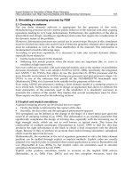
Figure 2.25: Shape discrepancy between two ellipsoids.
There is no indication that the approximation will be close to the true vol-
ume of intersection. Second, it is not clear why the approximation ellipsoid
is defined the way it is; an equally valid (but different) ellipsoid could be
obtained by using the principal axes of the actual ellipsoid, instead of those
of the desired ellipsoid.
Still another drawback is that this method is not a metric, and does not
result in a "distance" measurement. The measure results in a maximum
when the desired ellipsoid is completely contained in the actual ellipsoid.
It is possible that many differently-shaped manipulability ellipsoids could
contain a given desired ellipsoid; the volume of intersection method would
return the same result for each of these ellipsoids. It would not be possible
to identify any particular manipulability ellipsoid as being superior to the
others.
Finally, this method cannot handle degenerate ellipsoids. It is easier for
people to specify tasks as simple ellipsoids; one of the simplest is a line -
which can be viewed as an ellipsoid with only one non-zero principM axis.
(Such a desired ellipsoid would indicate that motion was only desired along
a single direction.) The volume method would always return zero in such
a case, providing no useful information.
Shape
discrepancy
The second method proposed by Lee compared the distance from the cen-
ter of the ellipsoids to their edges, along the principal axes of the desired
ellipsoid. See figure 2.25.
The darkened lines indicate the distances which were calculated as part
of the shape discrepancy measure. The complete measure which Lee used
2.6. Comparison of manipulability ellipsoids
69
was the reciprocal of the sum of squares of these lengths:
m
discrepancy = 1/E(dai
7,) 2 (2.55)
i=l
This measure is more useful than the volume of intersection, and pro-
vides information on the shape difference of the ellipsoids. It does not fail
with degenerate ellipsoids.
However, this measure still has flaws. First, the measure as given will
tend to infinity as the actual ellipsoid tends to the desired ellipsoid. This
can be remedied by not taking the reciprocal of the sum of squares; however,
even this modified measure still is not a metric, as the result from the actual
ellipsoid to the desired one is different than if the roles of the ellipsoid were
reversed.
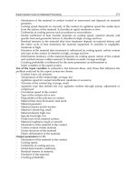
Intuitively, there are several ways to distinguish between two ellipsoids:
• translation: the centers of the ellipsoids are not located at the same
point in space.
• rotation: the corresponding principal axes of the ellipsoids point in
different directions.
scaling: the corresponding principal axes of the ellipsoids differ by a
constant scale factor; the principal axes of each ellipsoid have multi-
plicative relationships between the axes, and these relationships hold
for both ellipsoids, but the lengths of the corresponding axes are dif-
ferent.
shape discrepancy: the relationship between the lengths of the prin-
cipal axes in each ellipsoid differs, resulting in a different shape for
each ellipsoid.
Any metric function we choose must be able to handle the above cases.
In addition, the metric function must be able to handle degenerate ellipsoids
- which occurs when one or more principal axes of an ellipsoid has zero
length. One way of constructing such a metric is to determine a metric for
each of the above cases individually.
Define the following attributes of an ellipsoid:
• position of the center of the ellipsoid c.
,, m unit vectors pointing along the ellipsoid's principal axes ul, , urn.
• m lengths of the principal axes al, , am.
70 m
Chapter 2. Kinematic manipulability of general mechanical systems
Translation Rotation Scaling
Shape Discrepancy Degeneracy
Figure 2.26: Comparison between ellipsoids
The following functions are proposed for comparing ellipsoids. Proofs
showing that they are indeed metrics can be found in [19]. (Strictly speak-
ing, the functions are semi-metrics; however, each function can be made
into a metric by considering all ellipsoids which result in the function being
zero as belonging to the same equivalent class.)
translation:
~(~1, ~2) = lie2 all] = V/(c2 - cl)T(c2 el) (2.56)
where ci is the location of the center of ellipsoid i.
rotation:
m
c~(E1,E2) = E ~/1-cos¢(iU~i)],[u~i)]) (2.57)
i=1
where [u~ i)] and [u~ i)] are the ith (nondirectional) principal axes of el-
lipsoids 1 and 2, respectively. That is, [u (i)] is the union of the vectors
u (i) and -u (i) .
The function ¢ ([ul], [us]) = min{0(ul, u2),
O(-ui, us)).
scaling:
7(6, E2) = 1) - o s) l (2.58)
2.6. Comparison of manipulability ellipsoids
71
shape
discrepancy:
/~(£i, E2) = ~ I~l 1) - e~2) t (2.59)
i=1
where:
_(j) if > 0
ei = if a~ j) = 0 (2.60)
A weighted sum of these functions is itself a metric function, provided
that the weights are nonnegative. (If the weights are all positive, the
weighted sum is a true metric.) This formulation has the advantage that
certain aspects of the "distance" between ellipsoids can be emphasized if it
would help in optimizing a certain task. For example, if the orientation of
the ellipsoid was found to be more important to some task than the scaling
of the ellipsoid, the orientation component could have a larger weighting in
the calculation of the composite metric.
It is important to note that all of the component functions still return
useful results, even if the lengths of one or more of the principal axes of
the ellipsoids is zero (where the ellipsoid is degenerate). This is because
none of the functions depend upon the lengths of the principal axes being
non-zero.
To provide some general insight into the values returned from these
metrics, Figures 2.27-2.29 illustrate the results of the rotational, scale and
shape discrepancy metrics. The translational metric is not shown, as it
is fairly well understood. Note that while the metric functions work for
ellipsoids of other dimensions, two-dimensional ellipsoids are used in these
examples because they are the easiest to visualize.
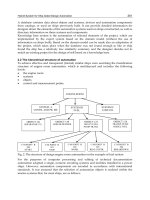
Figure 2.27 shows a two-dimensional reference ellipsoid (depicted by a
solid line) and several other ellipsoids (shown with dotted lines) rotated
in increments of 30 °. The corresponding values of a are shown next to
these ellipsoids. Note that c~ achieves a maximum value of 2 when the
ellipsoids are 90 ° apart. A check of the formula for a shows that in general,
the maximum value it can attain is m - which would happen when all m
corresponding principal axes of the ellipsoids being compared are at right
angles to each other.
Figure 2.28 shows a reference ellipsoid, along with several ellipsoids
which have different shapes. The values of/~ are shown next to each ellip-
soid. Note that the fl increases as the shape of the ellipsoid differs more
greatly from the initial form. The maximum value that ~ might attain is m
-
but this will only happen under special circumstances. For this to occur,
72
Chapter 2. Kinematic manipulability of
general
mechanical systems
the one ellipsoid would have to be a ball (all principal axes are of the same
length), while the other ellipsoid would have to be a point (all principal
axes are of zero length). More generally, the maximum attainable value of
/3 would be ~.m (1), (1)
1 ai /al ,
which would occur when the second ellipsoid was
a point.
Figure 2.29 shows some results of the scaling metric. As the ellipsoids
get larger or smaller than the reference ellipsoid (where size is determined
by the largest singular value), "7 becomes larger. As the second ellipsoid
increases in size, "7 ~ oo.
The range of values which the metrics can attain is summarized below:
c~ : 0< >m
: 0< >m
~/ :
O< >oo
6
: 0¢
>oo
(2.61)
Figures 2.30 - 2.32 show some two-dimensional ellipsoids which differ in
more than one aspect, and the resultant metric values. Figure 2.30 shows
two identically shaped ellipsoids which are rotated and translated relative
to each other. Note that the appropriate metrics indicate this difference;
however, the shape discrepancy and scale metrics return zero (because the
ellipsoids have the same shape and scale).
Figure 2.31 show two ellipsoids of different shape, centered at the same
point. They are rotated slightly with respect to each other. The ellipsoids'
longest principal axes are identical in length. In this case, the translation
metric and the scale metric return zero, while the rotational metric and the
shape discrepancy metric return non-zero values, indicating a difference
between the two ellipsoids.
Figure 2.32 shows two ellipsoids which have the same translational and
rotational position, but which are shaped and scaled differently. Again,
only the metrics which pertain to shape and scale return non-zero values.
It may be the case that which metrics are emphasized will be dependent
upon the task being performed. For example, in controlling a pool cue, the
exact rotation of the ellipsoid may not be important, as long as the robot
can readily move the cue in the needed direction. Translation would be
important, since a translational error would indicate that the tip of the
pool cue is positioned incorrectly. The shape of the ellipsoid would also
be important, because we would want to most readily move in the desired
direction, while resisting disturbances in other directions.
If the robot has a different task, such as picking up and moving an
object, other metrics may be more important. If the exact location on the
2. 7. Conclusions
73
t.5
-0.5
-1
-1.5
Rotational Metric for Two Dimensional Ellipsoids
w
2.0000
1.4142 ~ ,/ ,," - ~ . " - 1~,4142
/ ";' ,, . )(
0.7321 i ;; " "-, ,, "" ~' _~ 0.7321
(-
/ ,,u,',;
,, ,
X % i L ~
o \
,.\ .! /~, .\
)
\ ," T,.?, ,i/c ", J
, ;4,_ / ~.~ /,* ~
l I t \~ I p I \
/ ~\,.
t ~ .f I
x
I I
'-o:s
,:5
Figure 2.27: Metric example 1: The values of a for several different orien-
tations.
object that the gripper contacts is not critical, then the translational metric
may not be that important. The shape of the ellipsoid would be important
(and rotation somewhat less so), since the end-effector should have good
mobility in the direction the object should be moved, but should have very
short dimension in the vertical axis (the direction force must be applied in
order to lift the object).
2.7 Conclusions
This paper generalizes the velocity and force manipulability to general con-
strained multibody systems. Such systems include simple closed kinematic
chain as two arms jointly holding a payload, multiple kinematic chains as
in multi-finger grasping, and more complex structures as multiple Stewart
Platforms. We have extended the concept of stable grasp and manipulable
grasp in the multi-finger grasp literature to general mechanisms and pro-
vide necessary and sufficient conditions for their verifications. In general,
unstable (or nearly unstable) configurations need to carefully considered in
the kinematic analysis, otherwise there may be uncontrolled motion or large
joint loading. We have also shown that that multiple arm maniputability
74 Chapter 2. Kinematic manipulability o£
general
mechanical systems
2
1.5
1
0.5
0
-0.5
-1
-1.5
-2
Shape Discrepancy Metric for Two Dimensional Ellipsoids
'1
" "
0.6667 \
"
/ x
,' "
0.3333
".
II / 0 \ \~
0.3332
t\ x
/ ii
\XXXx / i
/
\ /
x /
o i i J
2 1:5 1 0',5 0 0',5 1 1',5 2
Figure 2.28: Metric example 2: The effect of altering the shape of the
ellipsoid on ~.
4
3
2
1
0
-1
-2
-3
-4
Scale Metric for Two Dimensional Ellipsoids
/ // ~ !
/ .,/ I
/'// / / I I i !
// / I I
/ // ii ///
/ /
/// //~ /// //
/// /// // ///
/ / // /
// // // //
i/ ii
///
/ 0 ii /
/ i /
! / /
i /
j/ //
t /
,, / / //
4.5
3.0 / /
t
/
/
(!
i I
Figure 2.29: Metric example 3: The values of "7 for a series of scaled ellip-
soids.
2. 7. Conclusions
75
't,5
1
0.5
0
-0,5
-1
-1.5[",
-1
Two Ellipsoids Differing Only in Rotation and Translation
-o'.~ o o'.~ ; i'.s
Figure 2.30: Metric example 4: a = 1.5874, fl = 0, "~ = 0, 5 = 0.5.
1.5
1
0.5
-0.5
-1
Two Ellipsoids Differing In Rotation and Shape
-1.5
-l:s -~ -o:~ ~ o:S ~ 1:5
Figure 2.31: Metric example 5: ~ = 0.2465, ~ 0.361, ~, = 0, 5 = 0.
76__ Chapter 2. Kinematic manipulability of general mechanical systems
1.5
1
0.5
0
-0.5
-1
Two
Ellipsoids Differing In Shape end
Scale
-15 -0: ' -
-1.5
-1 -0.5 5 1 1.5
Figure 2.32: Metric example 6: a = 0, fl = 0.2361, 7 = 0.809, ~ = 0.
can be significantly modified through the bracing by arms. Several metrics
for comparing ellipsoids are presented to guide the choice of brace location
and contact condition. Future work will include optimal kinematic synthe-
sis based on the manipulability ellipsoids and consideration of dynamics
and control.
Acknowledgments
This work is supported in part by the Center for Advanced Technology in
Automation, Robotics & Manufacturing under a block grant from the New
York State Science and Technology Foundation.
References
[1] T. Yoshikawa. Manipulability of robotic mechanisms. International
Journal of Robotic Research, 4(2):3-9, 1985.
[2] F. Park. Manipulability of closed kinematic chains, submitted to
ASME Journal on Mechanical Design, 1997.
REFERENCES
77
[3]
P. Chiacchio, S. Chiaverini, L. Sciavicco, and B. Siciliano. Reply
to "comments on 'global task space manipulability ellipsoids for
multiple-arm systems' and further considerations".
IEEE Transac-
tions on Robotics and Automation,
9(2):235-236, April 1993.
[4]
A. Bicchi, C. Melchiorri, and D. Balluchi. On the mobility and
manipulability of general multiple limb robots.
IEEE Transactions
on Robotics and Automation,
11(2):215-228, April 1995.
[5]
M. Uchiyama and P. Dauchez. Symmetric kinematic formulation
and non-master/slave coordinated control of two-arm robots.
Ad-
vanced Robotics: The international Journal of the Robotics Society
of Japan,
7(4):361-383, 1993.
[6]
V.R. Kumar and K.J. Waldron. Force distribution in closed kine.
matic chains.
IEEE Journal of Robotics and Automation,
4(6):657-
664, December 1988.
[71
C.A. Klein and S. Kittivatcharapo~.g. Optimal force distribution
for the legs of a walking machine with friction cone constraints.
IEEE Transaction on Robotics and Automation,
6(1):73-85, Febru-
ary 1990.
[8]
P. Chiaccbio, S. Chiaverini, L. Sciavicco, and B. Siciliano. Global
task space manipulability ellipsoids for multiple-arm systems.
IEEE
Transactions on Robotics and Automation,
7(5):678-685, October
1991.
[9]
C. Melchiorri. Comments on 'global task space manipulability ellip-
soids for multiple-arm systems' and further considerations.
IEEE
Transactions on Robotics and Automation,
9(2):232-235, April
1993.
[10]
A. Bicchi and C. Melchiorri. Manipulabitity measures of cooperat-
ing arms. In
Proceedings of the 1993 American Controls Conference,
pages 321-325, San Francisco, CA, June 1993.
[11]
S. Lee. Dual redundant arm configuration optimization with task-
oriented dual arm manipulability.
IEEE Transactions on Robotics
and Automation,
5(1):78-97, February 1989.
[12]
H. West.
Kinematic Analysis for the Design and Control of Braced
Manipulators.
PhD thesis, Massachusetts Institute of Technology,
1984.
78
[13]
[141
[15]
[16]
[17]
[18]
Chapter 2. Kinematic manipulability of general mechanical systems
C. Gosselin. The optimum design of robotic manipulators using
dexterity indices. In Robotics and Autonomous Systems 9, pages
213-226. Elsevier Science Publishers, 1992.
F. Ranjbaran, J. Angeles, and A. Kecskemethy. On the kinematic
conditioning of robotic manipulators. In Proceedings of the 1996
IEEE International Conference on Robotics and Automation, pages
3167-3172, Minneapolis, MN, 1996.
C. A. Klein and B. E. Blaho. Dexterity measures for the design
and control of kinematically redundant manipulators. International
Journal of Robotic Research, 6(2):72-83, summer 1987.
Z. Li, P. Hsu, and S. Sastry. Grasping and coordinated manip-
ulation by a multifingered robot hand. International Journal of
Robotic Research, 8(4):33-50, August 1989.
S. Lee and S. Kim. A self-reconfigurable dual-arm system. In
Proceedings of the 1991 IEEE International Conference on Robotics
and Automation, pages 164-169, Sacramento, CA, April 1991.
T. Yoshikawa. Analysis and control of robot manipulators with re-
dundancy. In M. Brady and R. Paul, editors, Robotics Research:
The First International Symposium, pages 735-747. MIT Press,
1984.
[19] L. Wilfinger. Robotic bracing. Doctoral Candidacy Proposal, 1997.
Chapter 3
Kinematic control of
dual-arm systems
This chapter focuses on the control problem for cooperative manipulator
systems in the framework of kinematic control. The control problem is
solved in two stages: first, an inverse kinematics problem is solved to trans-
form cooperative task variables into the corresponding joint variables for all
the manipulators constituting the cooperative system; then, the obtained
joint variables are fed to a suitable joint space control scheme. A useful
feature of the chosen approach is that coordination is solved at inverse kine-
matics level while arm interactions can be handled at joint control level.
An effective formulation is presented which fully characterizes a coordi-
nated motion task in terms of a set of meaningful position and orientation
variables. A closed-loop algorithmic approach for the inverse kinematics
problem is pursued based on differential kinematics mappings; this also
allows handling of kinematic redundancy and singular configurations.
A joint-space control scheme based on kineto-static filtering of the joint
errors is presented which is aimed at canceling out the internal force at
steady state without using force measurements. Nevertheless, when force
sensors are available, feedback of the internal forces can be added to im-
prove performance of the system. Stability analysis is provided and asymp-
totic stability of a set of equilibrium points is demonstrated. The case of
imperfect compensation of the gravity terms is also discussed.
79
80
Chapter 3. Kinematic control of dual-arm systems
3.1 Introduction
The two main goals of the control problem for cooperative manipulators
are coordinated motion of multiple-arm systems and handling of internal
forces arising from arm interactions through a commonly held object. In
order to achieve these goals, a number of major aspects must be taken into
account.
First, specification of the cooperative task requires definition of a set
of variables which are meaningful to the user and still allow a complete
description of the objectives of the cooperation.
Then, the control scheme should be robust to the occurrence of sin-
gular configurations of the cooperative system; moreover, the capability
of exploiting redundant degrees of freedom possibly present in the system
should be provided.
When the cooperative manipulator system results from grouping in-
dividual robot systems, i.e. arm plus controller, it would be desirable to
adopt a cooperative control scheme that takes advantage at the most of the
decentralized structure inherent to the available hardware.
Looking forward to industrial application of cooperative manipulator
systems, the use of force sensors should not be crucial to functioning of the
control scheme. In this respect, it is assumed that reduced performance is
acceptable for a control scheme not requiring force measurement.
In view of the above aspects, we have chosen to deal with the control
problem for cooperative manipulator systems by resorting to a kinematic
control approach. This means that the control problem is solved in two
stages: first, an inverse kinematics problem is solved to transform cooper-
ative task variables into the corresponding joint variables for all the ma-
nipulators constituting the cooperative system; then, the obtained joint
variables are fed to a suitable joint space control scheme. A useful feature
of the chosen approach is that coordination is solved at inverse kinematics
level while arm interactions can be handled at joint control level.
To set up an inverse kinematics for cooperative manipulator systems
it is first necessary to find a task description that allows specification of
coordinated motion. To this purpose, it should be obvious that taking the
end-effector position and orientation of each manipulator as task variables
is inadequate, since the system would be regarded as composed by inde-
pendent manipulators and coordination management would be left to the
user. An effective formulation is presented in this chapter which fully char-
acterizes a coordinated motion task in terms of a set of meaningful position
and orientation variables.
Finding closed-form solutions to the inverse kinematics problem is pos-
sible only for special manipulator geometries and simple coordination tasks.
3.2. Cooperative task description 81
An algorithmic approach shall be pursued instead based on differential kine-
matics mappings; this also allows handling of kinematic redundancy and
singular configurations. We resort to a closed-loop inverse kinematics al-
gorithm which does not suffer from numerical drift typical of open-loop
algorithms.
If an independent joint control law is used as second stage of the kine-
matic control scheme, arising of internal forces is expected. These forces
originate from different sources; namely, joint tracking errors causing vio-
lation of closed-chain constraints, joint trajectories not consistent with the
geometry of the grasp, non-compensated dynamics. The effect of the last
source can be effectively reduced only by resorting to model-based control
schemes; however, these schemes are computationally demanding for coop-
erative systems where also the (possibly unknown) dynamics of the object
plays a significant role.
To retain the simplicity of a scheme without dynamic compensation
we present a control scheme based on kineto-static filtering of the joint
errors aimed at reducing the building of internal forces. A simple PD-
type control law is described which is shown to cancel out the internal
force at steady state. Remarkably, this is obtained without using force
measurements. Nevertheless, when force sensors are available, feedback of
the internal forces can be added to improve performance of the system and
to achieve internal force regulation.
Stability analysis is developed for the equilibrium points of the coop-
erative system under the proposed joint-space control laws. By applying
the global invariant set theorem in a singularity-free region, asymptotic
convergence to the invariant set constituted by the equilibrium points is
demonstrated and local stability of the minimum norm equilibrium points
is analyzed. The analysis is extended also to the case of imperfect compen-
sation of the gravity terms.
3.2 Cooperative task description
Most available task formulations are based on a global description of the
system through the use of the so-called grasp matrix assuming that an ob-
ject is commonly held by the manipulators [1,2,3,4]; the result is a complete
description of the task at differential kinematics level. Position task vari-
ables can be easily found by integration of linear velocities while a problem
arises for orientation task variables, in view of the non-integrability of an-
gular velocities. It might be argued that a description of orientation could
be found by means of a minimal representation, e.g. Euler angles, but the
resulting variables would not allow a clear specification of a coordination
82
Chapter 3. Kinematic control of dual-arm systems
task for the user. To overcome this problem, a description of the coordi-
nated motion task will be sought in terms of a set of meaningful position
and orientation variables [5].
In the present work, a system of two cooperative manipulators, namely
manipulator 1 and manipulator 2, will be considered. In the remainder, the
subscript i will denote quantities referred to manipulator i. Let Ei denote
the frame attached to the end effector of manipulator i; quantities referred
to Ei will be denoted by the superscript i. Moreover, all quantities referred
to a common base frame Eb wilt be denoted by the superscript b.
Then, let pb be the (3 x 1) vector denoting the end-effector position as
the origin of Ei. Let also R b be the (3 × 3) rotation matrix expressing the
end-effector orientation, i.e., its columns represent the unit vectors of Zi.
In order to establish the sought task description, a suitable frame is to be
introduced to specify coordinated motion of the two-manipulator system.
Let such frame be termed as absolute frame and denoted by Za; quantities
referred to the absolute frame will be denoted by the superscript a.
The origin of the absolute frame is called
absolute position
of the coop-
erative system and can be expressed as a function of the positions of the
two end effectors. One simple choice is
pb= 1 b
~(Pl + P~). (3.1)
In order to define the absolute orientation of the system, consider the
matrix operator
Rk(O)
expressing the rotation by the angle 0 about the
axis aligned with the unit vector k = [ kx ky k~ IT [6]. Then, the rotation
matrix giving the
absolute orientation
can be defined as
b 1
Rba = R1Rk~ 2
(t912/2), (3.2)
where k~2 and 012 are respectively the unit vector and the angle that realize
the rotation described by
R~,
i.e., the orientation of frame 2 with respect
to frame 1. Therefore, the above choice corresponds to make a rotation
about axis k~2 by an angle which is half the angle needed to align R~ with
The absolute position and orientation describe the task in terms of the
composition of the position and orientation of the single manipulators and
thus it is clear that there exist infinite end-effector configurations giving
the same absolute position and orientation. Therefore, in order to fully
describe a coordinated motion, the position and orientation of one manip-
ulator relative to the other is also of concern.
The
relative position
between the two end effectors can be defined as
p~ = p~ - p~. (3.3)