Rapid Learning in Robotics - Jorg Walter Part 2 ppsx
Bạn đang xem bản rút gọn của tài liệu. Xem và tải ngay bản đầy đủ của tài liệu tại đây (225.78 KB, 16 trang )
3
plinary field of researchers from physiology, neuro-biology, cognitive and
computer science. Physics contributed methods to deal with systems con-
stituted by an extremely large number of interacting elements, like in a
ferromagnet. Since the human brain contains of about neurons with
interconnections and shows a — to a certain extent — homogeneous
structure, stochastic physics (in particular the Hopfield model) also en-
larged the views of neuroscience.
Beyond the phenomenon of “learning”, the rapidly increasing achieve-
ments that became possible by the computer also forced us to re-think
about thebefore unproblematic phenomena “machine” and “intelligence”.
Our ideas about the notions “body” and “mind” became enriched by the
relation to the dualism of “hardware” and “software”.
With the appearance of the computer, a new modeling paradigm came
into the foreground and led to the research field of artificial intelligence.It
takes the digital computer as a prototype and tries to model mental func-
tions as processes, which manipulate symbols following logical rules –
here fully decoupled from any biological substrate. Goal is the develop-
ment of algorithms which emulate cognitive functions, especially human
intelligence. Prominent examples are chess, or solving algebraic equa-
tions, both of which require of humans considerable mental effort.
In particular the call for practical applications revealed the limitations
of traditional computer hardware and software concepts. Remarkably, tra-
ditional computer systems solve tasks, which are distinctively hard for
humans, but fail to solve tasks, which appear “effortless” in our daily life,
e.g. listening, watching, talking, walking in the forest, or steering a car.
This appears related to the fundamental differences in the information
processing architectures of brains and computers, and caused the renais-
sance of the field of connectionist research. Based on the von-Neumann-
architecture, today computers usually employ one, or a small number of
central processors, working with high speed, and following a sequential
program. Nevertheless, the tremendous growth in availability of cost-
efficiency computing power enables to conveniently investigate also par-
allel computation strategies in simulation on sequential computers.
Often learning mechanisms are explored in computer simulations, but
studying learning in a complex environment has severe limitations - when
it comes to action. As soon as learning involves responses, acting on, or
inter-acting with the environment, simulation becomes too easily unreal-
4 Introduction
istic. The solution, as seen by many researchers is, that “learning must
meet the real world”. Of course, simulation can be a helpful technique,
but needs realistic counter-checks in real-world experiments. Here, the
field of robotics plays an important role.
The word “robot” is young. It was coined 1935 by the playwriter Karl
Capek and has its roots in the Czech word for “forced labor”. The first
modern industrial robots are even younger: the “Unimates” were devel-
oped by Joe Engelberger in the early 60's. What is a robot? A robot is
a mechanism, which is able to move in a given environment. The main
difference to an ordinary machine is, that a robot is more versatile and
multi-functional, and it can be programmed, or commanded to perform
functions normally ascribed to humans. Its mechanical structure is driven
by actuators which are governed by some controller according to an in-
tended task. Sensors deliver the required feed-back in order to adjust the
current trajectory to the commanded motion and task.
Robot tasks can be specified in various ways: e.g. with respect to a
certain reference coordinate system, or in terms of desired proximities,
or forces, etc. However, the robot is governed by its own actuator vari-
ables. This makes the availability of precise mappings from different sen-
sory variables, physical, motor, and actuator values a crucial issue. Often
these sensorimotor mappings are highly non-linear and sometimes very hard
to derive analytically. Furthermore, they may change in time, i.e. drift by
wear-and-tear or due to unintended collisions. The effective learning and
adaption of the sensorimotor mappings are of particular importance when
a precise model is lacking or it is difficult or costly to recalibrate the robot,
e.g. since it may be remotely deployed.
Chapter 2 describes work done for establishing a hardware infrastruc-
ture and experimental platform that is suitable for carrying out experi-
ments needed to develop and test robot learning algorithms. Such a labo-
ratory comprises many different components required for advanced, sensor-
based robotics. Our main actuated mechanical structures are an industrial
manipulator, and a hydraulically driven robot hand. The perception side
has been enlarged by various sensory equipment. In addition, a variety of
hardware and software structures are required for command and control
purposes, in order to make a robot system useful.
The reality of working with real robots has several effects:
5
It enlarges the field of problems and relevant disciplines, and in-
cludes also material, engineering, control, and communication sci-
ences.
The time for gathering training data becomes a major issue. This
includes also the time for preparing the learning set-up. In princi-
ple, the learning solution competes with the conventional solution
developed by a human analyzing the system.
The faced complexity draws attention also towards the efficient struc-
turing of re-usable building blocks in general, and in particular for
learning.
And finally, it makes also technically inclined people appreciate that
the complexity of biological organisms requires a rather long time of
adolescence for good reasons;
Many learning algorithms exhibit stochastic, iterative adaptation and
require a large number of training steps until the learned mapping is reli-
able. This property can also be found in the biological brain.
There is evidence, that learned associations are gradually enhanced by
repetition, and the performance is improved by practice - even when they
are learned insightfully. The stimulus-sampling theory explains the slow
learning bythe complexity and variations of environment (context) stimuli.
Since the environment is always changing to a certain extent, many trials
are required before a response is associated with a relatively complete set
of context stimuli.
But there exits also other, rapid forms of associative learning, e.g. “one-
shot learning”. This can occur by insight, or triggered by a particularly
strong impression, by an exceptional event or circumstances. Another
form is “imprinting”, which is characterized by a sensitive period, within
which learning takes place. The timing can be evengenetically programmed.
A remarkable example was discovered by Konrad Lorenz, when he stud-
ied the behavior of chicks and mallard ducklings. He found, that they im-
print the image and sound of their mother most effectively only from 13
to 16 hours after hatching. During this period a duckling possibly accepts
another moving object as mother (e.g. man), but not before or afterwards.
Analyzing the circumstances when rapid learning can be successful, at
least two important prerequisites can be identified:
6 Introduction
First, the importance and correctness of the learned prototypical asso-
ciation is clarified.
And second, the correct structural context is known.
This is important in order to draw meaningful inferences from the proto-
typical data set, when the system needs to generalize in new, previously
unknown situations.
The main focus of the present work are learning mechanisms of this
category: rapid learning – requiring only a small number of training data.
Our computational approach to the realization of such learning algorithm
is derived form the “Self-Organizing Map” (SOM). An essential new in-
gredient is the use of a continuous parametric representation that allows
a rapid and very flexible construction of manifolds with intrinsic dimen-
sionality up to 4 8 i.e. in a range that is very typical for many situations
in robotics.
This algorithm, is termed“Parameterized Self-Organizing Map”(PSOM)
and aims at continuous, smooth mappings in higher dimensional spaces.
The PSOM manifolds have a number of attractive properties.
We show that the PSOM is most useful in situations where the structure
of the obtained training data can be correctly inferred. Similar to the SOM,
the structure is encoded in the topological order of prototypical examples.
As explained in chapter 4, the discrete nature of the SOM is overcome by
using a set of basis functions. Together with a set of prototypical train-
ing data, they build a continuous mapping manifold, which can be used
in several ways. The PSOM manifold offers auto-association capability,
which can serve for completion of partial inputs and simultaneously map-
ping to multiple coordinate spaces.
The PSOM approach exhibits unusual mapping properties, which are
exposed in chapter 5. The special construction of the continuous manifold
deserves consideration and approaches to improve the mapping accuracy
and computational efficiency. Several extensions to the standard formu-
lations are presented in Chapter 6. They are illustrated at a number of
examples.
In cases where the topological structure of the training data is known
beforehand, e.g. generated by actively sampling the examples, the PSOM
“learning” time reduces to an immediate construction. This feature is of
particular interest in the domain of robotics: as already pointed out, here
7
the cost of gathering the training data is very relevant as well as the avail-
ability of adaptable, high-dimensional sensorimotor transformations.
Chapter 7 and 8 present several PSOM examples in the vision and the
robotics domain. The flexible association mechanism facilitates applica-
tions: feature completion; dynamical sensor fusion, improving noise re-
jection; generating perceptual hypotheses for other sensor systems; vari-
ous robot kinematic transformation can be directly augmented to combine
e.g. visual coordinate spaces. This even works with redundant degrees of
freedom, which can additionally comply to extra constraints.
Chapter 9 turns to the next higher level of one-shot learning. Here the
learning of prototypical mappings is used to rapidly adapt a learning sys-
tem to new context situations. This leads to a hierarchical architecture,
which is conceptually linked, but not restricted to the PSOM approach.
One learning module learns the context-dependent skill and encodes
the obtained expertise in a (more-or-less large) set of parameters or weights.
A second meta-mapping module learns the association between the rec-
ognized context stimuli and the corresponding mapping expertise. The
learning of a set of prototypical mappings may be called an investment
learning stage, since effort is invested, to train the system for the second,
the one-shot learning phase. Observing the context, the system can now
adapt most rapidly by “mixing” the expertise previously obtained. This
mixture-of-expertise architecture complements the mixture-of-experts archi-
tecture (as coined by Jordan) and appears advantageous in cases where
the variation of the underlying model are continuous within the chosen
mapping domain.
Chapter 10 summarizes the main points.
Of course the full complexity of learning and the complexity of real robots
is still unsolved today. The present work attempts to make a contribution
to a few of the many things that still can be and must be improved.
8 Introduction
Chapter 2
The Robotics Laboratory
This chapter describes the developed concept and set-up of our robotic
laboratory. It is aimed at the technically interested reader and explains
some of the hardware aspects of this work.
A real robot lab is a testbed for ideas and concepts of efficient and intel-
ligent controlling, operating, and learning. It is an important source of in-
spiration, complication, practical experience, feedback, and cross-validation
of simulations. The construction and working of system components is de-
scribed as well as ideas, difficulties and solutions which accompanied the
development.
For a fuller account see (Walter and Ritter 1996c).
Two major classes of robots can be distinguished: robot manipulators
are operating in a bounded three-dimensional workspace, having a fixed
base, whereas robot vehicles move on a two-dimensional surface – either
by wheels (mobile robots) or by articulated legs intended for walking on
rough terrains. Of course, they can be mixed, such as manipulators mounted
on a wheeled vehicle, or e.g. by combining several finger-like manipula-
tors to a dextrous robot hand.
2.1 Actuation: The Puma Robot
The domain for setting up this robotics laboratory is the domain of ma-
nipulation and exploration with a 6 degrees-of-freedom robot manipulator
in conjunction with a multi-fingered robot hand.
The compromise solution between a mature robot, which is able to
J. Walter “Rapid Learning in Robotics” 9
10 The Robotics Laboratory
Figure 2.1: The six axes Puma robot arm with the TUM multi-fingered hand
fixating a wooden “Baufix” toy airplane. The 6D force-torque sensor (FTS) and
the end-effector mounted camera is visible, in contrast to built-in proprioceptive
joint encoders.
2.1 Actuation: The Puma Robot 11
~
Host
(Sun Pool)
Host
(SGI Pool)
Host
(IBM Pool)
Host
(NeXT Pool)
Host
(PC Pool)
Host
(DEC Pool)
~
~
~
~
motor
driver
DA
conv
VME-Bus
Parallel Port
LSI 11
6503
Motor
Drivers +
Sensor
Interfaces
PUMA
Robot
Controller
6 DOF
Timer
DLR
BusMaster
BRAD
Force/
Torque
Wrist
Sensor
Fingertip
Tactile
Sensors
D/A
conv
A/D
conv
Digital
ports
motor
driver
motor
driver
Motor
Driver
motor
driver
motor
driver
motor
driver
Presssure
/Position
Sensors
DSP
image
processing
(Androx)
DSP
Image
Processing
(Androx)
VME-Bus
Manipulator
Wrist
Sensor
Tactile
Sensors
Hydraulic Hand
Image
Processing
LAN Etherne
t
Pipeline
Image
Processing
(Datacube)
~
~
M-module Interface
Parallel Port
S-bus / VME
"argus"
Host
(SUN Sparc 20)
"druide"
Host
(SUN Sparc 2)
"manus"
Controller
( 68040)
3D Space-
Mouse
3D Space-
Mouse
S-bus / VME
Active
Camera
System
Laser
Light
Light
Light
~
~
Life-Bit
Misc.
Figure 2.2: The Asymmetric Multiprocessing “Road Map”. The main hardware
“roads” connect the heterogeneous system components and lay ground for var-
ious types of communication links. The LAN Ethernet (“Local Area Network”
with TCP/IP and max. throughput 10Mbit/s) connects the pool of Unix com-
puter workstations with the primary “robotics host” “druide” and the “active vi-
sion host” “argus” . Each of the two Unix SparcStation is bus master to a VME-bus
(max 20MByte/s, with 4MByte/s S-bus link). “argus” controls the active stereo
vision platform and the image processing system (Datacube, with pipeline ar-
chitecture). “druide” is the primary host, which controls the robot manipulator,
the robot hand, the sensory systems including the force/torque wrist sensor, the
tactile sensors, and the second image processing system. The hand sub-system
electronics is coordinated by the “manus” controller, which is a second VME bus
master and also accessible via the Ethernet link. (Boxes with rounded corners
indicate semi-autonomous sub-systems with CPUs enclosed.)
12 The Robotics Laboratory
carry the required payload of about 3 kg and which can be turned into an
open, real-time robot, was found with a Puma 560 Mark II robot. It is prob-
ably “the” classical industrial robots with six revolute joints. Its geome-
try and kinematics
1
is subject of standard robotics textbooks (Paul 1981;
Fu, Gonzalez, and Lee 1987). It can be characterized as a medium fast
(0.5 m/s straight line), very reliable, robust “work horse” for medium pay
loads. The action radius is comparable to the human arm, but the arm is
stronger and heavier (radius 0.9 m; 63 kg arm weight). The Puma MarkII
controller comprises the power supply and the servo electronics for the
six DC motors. They are controlled by six parallel microprocessors and
coordinated by a DEC LSI-11 as central controller. Each joint micropro-
cessor (Rockwell 6503) implements a digital PD controller, correcting the
commanded joint position periodically. The decoupled joint position control
operates with 1 kHz and originally receives command updates (setpoints)
every 28 ms by the LSI-11.
In the standard application the Puma is programmed in the interpreted
language VAL II, which is considered a flexible programming language by
industrial standards. But running on the main controller (LSI-11 proces-
sor), it is not capable of handling high bandwidth sensory input itself (e.g.,
from a video camera) and furthermore, it does not support flexible control
by an auxiliary computer. To achieve a tight real-time control directly by
a Unix workstation, we installed the software package RCI/RCCL (Hay-
ward and Paul 1986; Lloyd 1988; Lloyd and Parker 1990; Lloyd and Hay-
ward 1992).
The acronym RCI/RCCL stands for Real-time Control Interface and Robot
Control C Library. The package provides besides the reprogramming of the
robot controller a library of commands for issuing high-level motion com-
mands in the C programming language. Furthermore, we patched the Sun
operating system OS 4.1 to sufficient real-time capabilities for serving a re-
liable control process up to about 200Hz. Unix is a multitasking operating
system, sequencing several processes in short time slices. Initially, Unix
was not designed for real-time control, therefore it provides a regular pro-
cess only with timing control on a coarse time scale. But real-time process-
ing requires, that the system reliably responds within a certain time frame.
RCI succeeded here by anchoring the synchronous trajectory control task
1
Designed by Joe Engelberger, the founder of Unimation, sometimes called the father
of robotics. Unimation was later sold to Westinghouse Inc., AEG and last to Stäubli.
2.1 Actuation: The Puma Robot 13
(a special thread) at a special device driver serving the interrupts from a
timer card. The control task is thus running independently and outside
the planning task. By this means, sensory information (e.g. camera or force
sensors) can be processed and feedback in a very effective and convenient
manner.
For example, by default our DLR 6 D wrist sensor is read out about the
currently exerted force and torque vector (3+3=6D) between the robot arm
and the robot hand (Fig. 2.1, 2.4). The DLR Force-Torque-Sensor (FTS) was
developed by the robotics group of Prof. Hirzinger of the DLR, Oberpfaf-
fenhofen, and is a spin-off from the ROTEX Spacelab mission D2 (Hirzinger,
Brunner, Dietrich, and Heindl 1994). As indicated in Fig. 2.2, the FTS is
an micro-controller based sensory sub-system, which communicates via a
special field-bus with the VME-bus.
Force
Control
Law
Guard
Coordinate
transform
Coordinate
transform
Position
Controller
Coordinate
transform
+ Gravity
Compens.
1-S
S
+
-
Robot
+
Environment
Sensory
Pattern
X
des
X
trans
F
des
F
meas
F
trans
X
θ
des
θ
meas
θ
meas
(Sun "druide") (Puma Controller)
Figure 2.3: A two-loop control scheme for the mixed force and position control.
The inner, fast loop runs on the joint micro controller within the Puma controller,
the outer loop involves the control task on “druide”.
The resulting robot control system allows us to implement hybrid con-
trol architectures using the position control interface. This includes multi-
sensor compliant motions with mixed force controlled motions as well as
controlling an artificial spring behavior. The main restriction is the diffi-
culty in controlling forces with high robot speeds. High speed motions
14 The Robotics Laboratory
with environment interaction need quick response and therefore require,
a very high frequency of the digital force control loop. The bottleneck
is given by the Puma controller structure. The realizable force control in-
cludes a fast inner position loop (joint micro controller) with a slower outer
force loop (involving the Sun “druide”). But still, by generating the robot
trajectory setpoints on the external Sun workstation, we could double the
control frequency of VAL II and establish a stable outer control loop with
65 Hz.
Fig. 2.3 sketches the two-loop control scheme implemented for the mixed
force and position control of the Puma. The inner, fast loop runs on the
joint micro controller within the Puma controller, the outer loop involves
the control task on the Sun workstation “druide”. The desired position
and forces are given for a specified coordinate system (here writ-
ten as generalized 6 D vectors: position and orientation in roll, pitch, yaw
(see also Fig. 7.2 and Paul 1981) and generalized
force ). The control law transforms the force
deviation into a desired position. The diagonal selection matrix elements
in S choose force controls (if 1) or position control (if 0) for each axis, fol-
lowing the idea of Cartesian sub-space control
2
. The desired position is
transformed and signaled to the joint controllers, which determine appro-
priate motor power commands. The results of the robot - environment in-
teraction is monitored by the force-torque sensor measurement and
transformed to the net acting force after the gravity force compu-
tation. The guard block checks on specified sensory patterns, e.g., force-
torque ranges for each axes and whether the robot is within a safe-marked
work space volume. Depending on the desired action, a suitable controller
scheme and sets of parameters must be chosen, for example, S, gains, stiff-
ness, safe force/position patterns). Here the efficient handling and access
of parameter sets, suitable for run-time adaptation is an important issue.
2
Examples for suitable selection matrices are: S=diag(0,0,1,0,0,0) for a compliant mo-
tion with a desired force in direction, or S=diag(0,0,1,1,1,0) for aligning two flat sur-
faces (with surface normal in ). A free translation and -rotational follow controller in
Cartesian space can be realized with S=diag(1,1,1,0,0,1). See (Mason and Salisbury 1985;
Schutter 1986; Dücker 1995).
2.1 Actuation: The Puma Robot 15
Figure 2.4: The endeffector. (left:) Between the arm and the hydraulic hand, the
cylinder shaped FTS device can measure current 6D force torque values. The
three finger modules are mounted here symmetrically at the 12 sided regular
prism base. On the left side, the color video camera looks at the scene from an
end-effector fixed position. Inside the flat palm, a diode laser is directed in tool
axis, which allows depth triangulation in the viewing angle of the camera.
16 The Robotics Laboratory
2.2 Actuation: The Hand “Manus”
For the purpose of studying dextrous manipulation tasks, our robot lab is
equipped with an hydraulic robot hand with (up to) four identical 3-DOF
fingers modules, see Fig. 2.4. The hand prototype was developed and built
by the mechanical engineering group of Prof. Pfeiffer at the Technical Uni-
versity of Munich (“TUM-hand”). We received the final hand prototype
comprising four completely actuated fingers, the sensor interface, and mo-
tor driver electronics. The robot finger's design and its mobility resembles
that of the human index finger, but scaled up to about 110 %.
Figure 2.5: The kinematics of
the TUM robot finger. The car-
danic base joint allows 15
side-
wards gyring (
) and full ad-
duction (
) together with two
coupled joints (
). (after
Selle 1995)
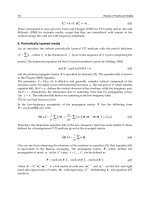
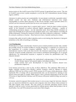
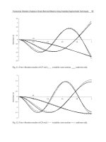
Fig. 2.5 displays the kinematics of one finger. The particular kinematic
mapping (from piston location to joint angles and Cartesian position) of
the cardanic joint configuration is very hard to invert analytically. Selle
(1995) describes an iterative numerical procedure. This sensorimotor map-
ping is a challenging task for a learning algorithm. In section 8.1 we will
take up this problem and present solutions which achieve good accuracy
with a fairly small number of training examples.
2.2 Actuation: The Hand “Manus” 17
2.2.1 Oil model
The finger joints are driven by small, spring loaded, hydraulic cylinders,
which connect each actuator to the base station by a oil hose. In contrast
to the more standard hydraulic system with a central power supply and
valve controlled bi-directional powered cylinder, here, each finger cylin-
der is one-way powered from a corresponding cylinder at the base sta-
tion. Unfortunately, the finger design does not foresee integrated sensors
directly at the fingers.
Motor
X
m
X
f
A
f
A
m
k
Finger
p
B
ase Station
pistonEx
t.
F
Oil Hose
κ
Figure 2.6: The hydraulic oil system.
The control system has to rely on indirect feedback sensing through
the oil system. Fig. 2.6 displays the location of the two feedback sensors.
In each degree of freedom the piston position of the motor cylin-
der (linear potentiometer) and the pressure in the closed oil system
(membrane sensor with semi-conductor strain-gauge) is measured at the
base station. The long oil hose is not perfectly stiff, which makes this oil
system component significantly expandable (4 m, large surface to volume
ratio). This bears the advantage of a naturally compliant and damped sys-
tem but bears also the disadvantage, that even pure position control must
consider the force - position coupled oil model (Menzel et al. 1993; Selle
1995; Walter and Ritter 1996c).
2.2.2 Hardware and Software Integration
The modular concept of the TUM-hand includes its interface electronics.
Each finger module has its separate motor servo electronics and sensor
amplifiers, which we connected to analog converter cards in the VME bus
system as illustrated in the lower right part of Fig. 2.2. The digital hand
control process is running at “manus”, a VME based embedded 68040 pro-
18 The Robotics Laboratory
cessor board. Following the example of RCCL, the “Manus Control C
Library” (MCCL) was developed and implemented (Rankers 1994; Selle
1995). To facilitate an arm-hand unified planning level, the Unix work-
station “druide” is set up to issue finger motion (piston, joint, or Cartesian
position) and force control requests to the “manus” controller (Fig. 2.2).
Further
Fingertip
Sensors
Oil Model
Finger
State
Estimation
+
-
τ
-
Finger
Cylinder
+
Environment
X
f, des
F
f, des
K
-1
PD
Controller
DC Motor
and
Oil Cylinder
e
X
f, estim
F
f, estim
X
m
p
Oil System
F
e
xt
X
f
F
friction
Figure 2.7: A control scheme for the mixed force and position control running on
the embedded VME-CPU “manus”. The original robot hand design allows only
indirect estimation of the finger state utilizing a model of the oil system. Certain
kinds of influences, especially friction effects require extra information sources to
be satisfyingly accounted for – as for example tactile sensors, see Sec. 2.3.
The achieved performance in dextrous finger control is a real challenge
and led to the development of a simulator package for a more detailed
study of the oil system (Selle 1995). The main sources of uncertainty are
friction effects in combination with the lack of direct sensory feedback.
As illustrated in Fig. 2.7, extra sensory information is required to fill this
gap. Particularly promising are different kinds of tactile sense organs. The
human skin uses several types of neural receptors, sensitive to static and
dynamic pressure in a remarkable versatile manner.
In the following section extensions to the robot's senses are described.
They are the prerequisite for more intelligent, semi-autonomous robotic
systems. As already mentioned, todays robots are usually restricted to
the proprioceptors of their actuator positions. For environment interac-
tion two categories can be distinguished: (i) remote senses, which are
mediated, e.g. by light, and (ii) direct senses in case parts of the robot
are in contact. Measurements to obtain force-torque information are the
FTS-wrist sensor and the finger state estimation as mentioned above.