Recent Advances in Mechatronics - Ryszard Jabonski et al (Eds) Episode 1 Part 10 ppt
Bạn đang xem bản rút gọn của tài liệu. Xem và tải ngay bản đầy đủ của tài liệu tại đây (2.79 MB, 40 trang )
Fig. 4. Examples of soldering problems: a) the SOT23 – Sn wetability problems,
b) the QFP64 pitch 0.5 component – small pitch and pad design problems.
Probably a nitrogen atmosphere and improve pads design near the QFP64
components should improve wave soldering results in this situation. The
further investigations are planning in this subject.
Summary
Printing process is the most critical during assembly of complex PCBs in
lead-free technology.
The dedicated nozzles for pick and place machine are essential for assem-
bly components sizes: 0201 or smaller as also BGA and CSP.
The complex PCB in lead-free technology requires soldering profile with
about 250°C peak temperature and precise convection oven with 5 or more
heating zones.
The minimalization of thermal processes previous a wave soldering, good
quality of PCB finish, adequate PCB pads design and more active flux are
recommend for lead-free wave soldering of complex boards.
Acknowledgements
This work was realized as a part of the GreenRoSE - Collective Re-
search Project – 2004-500225 funded by the EC under the 6FP.
References
[1] Directive 2002/95/EC on the restriction of the use of certain hazardous
substances in electrical and electronic equipment, Official Journal of the
European Union, 13.02.2003, pp. 19-23
[2] J. Klerk, „Large & Complex Boards“. ELFNET at SEMICON Confer-
ence, 5-6th April 2006, Munich, Germany
344 J. Sitek, Z. Drozd, K. Bukat
Applying Mechatronic Strategies in Forming
Technology Using the Example of Retrofitting
a Cross Rolling Machine
R. Neugebauer, D. Klug, M. Hoffmann, T. Koch
Fraunhofer Institute for Machine Tools and Forming Technology
Reichenhainer Straße 88, Chemnitz, 09126, Germany
Abstract
A machine for manufacturing bulk metal forming parts (a cross rolling
machine with flat jaws) will be used as an example to demonstrate the idea
of retrofitting metal forming machines that is based on linking single
mechatronic components to one overall mechatronic system. The purpose
of retrofitting was boosting the machine's performance range while ex-
panding its functionality. Ideas for applications will be developed sup-
ported by simulation and based on an analysis of the machine's system to
evaluate how they fit into the overall system. The foremost features of the
machine under analysis are the cascade-shaped regulation of the main hy-
draulic machine and secondary axes using decoupled physical factors and
the decentralized control structure distributed physically over several lev-
els. Selected experimental findings will demonstrate that this overall
mechatronic system can be used in practical applications.
1. Introduction
As with all modern production machines, metal forming machines are
constantly called upon to be increasingly productive, flexible and efficient.
Furthermore, the wide variety of materials to be worked and geometries to
be produced spells out increasing demands made upon the complexity of
the metal forming process. All of these requirements made of metal for-
ming machines means they have to be considered overall mechatronic sys-
tems. This not only applies to coming up with new metal forming machi-
nes. It also figures prominently in renewing and upgrading existing metal
forming machines (i.e., retrofitting).
Retrofitting not only has the purposes of modernizing metal forming ma-
chines and boosting process and machine reliability, but also upgrading the
range of the machine's applications. This can be done by using the machi-
ne's performance ranges to a greater extent or integrating new functionali-
ties. Meeting this target calls for including and efficiently taking advantage
of the opportunities offered at the intersection of mechanical engineering,
electrical engineering/electronics and information technology for the tech-
nological functioning of each metal forming machine system. Making ac-
tuator and sensor technology a part of the control and regulation design
and implementing them are major factors in translating the targets of retro-
fitting the machine into reality. The foremost technological factors are the
position and motion of the tool and work piece as well as the process
forces.
2. Problem Description
Cross rolling is a continuous metal forming process for manufacturing
graduated work pieces that are mostly symmetric to rotation with a high
degree of dimensional, shape and mass accuracy. Components range from
preform parts to finished shapes made of hollow or solid material. These
iron and non-ferrous materials are cold-, semi-warm or warm-formed whi-
le cross rolling is done on cross rolling machines with round tools or, as in
the case under consideration, cross rolling machines with flat jaws. Their
characteristic feature is pressure forming the work piece by means of tools
moving opposite one another that roll on the surface of the work piece and
put it into rotational motion. In addition to the classical field of bulk metal
forming technology (mass production with tools with a high degree of sha-
pe storage), cross rolling with flat jaws is a flexible forming technique for
small and medium parts numbers with partially meshing and partially low-
shape storage tools. While the machine structure on existing cross rolling
machines with flat jaws does not have any substantial means of enhancing
the production outcome in terms of quality, productivity and economical
efficiency, this can be brought about by using control engineering to im-
pact the complex interaction between the machine, tool and work piece as
shown by the subsequent example of retrofitting a cross rolling machine
with flat jaws. The reason for retrofitting this machine is not only to up-
grade the usable performance range (rolling force or sled speed) and im-
prove the control accuracy of the main axes (sled axes), but also to extend
346 R. Neugebauer, D. Klug, M. Homann, T. Koch
machine functionality (pendulum sled stroke) and integrate modular func-
tion axes (mandrel axes) into the higher-level control system. The mandrel
axes designed as modular function axes are used for rolling the hollow
components on the mandrel.
3. Strategy Development
The point of departure for meeting the target of retrofitting cross rollers
with flat jaws was an analysis and description of process factors relevant to
the forming technique that can be impacted by this machine structure such
as forming force, forming speed and forming path. They are used to calcu-
late the controller variables of speed, position and pressure applicable to
the specific hydraulic linear actuators in conformity with the basic physical
laws. The next step is upgrading hydraulic linear actuators to single hy-
draulic axes or single mechatronic components including or applying the
necessary sensor technology (path sensor or pressure sensor) and basic
regulation functionality (position and pressure). They were combined into
functional groups (combined axes) as the overall mechatronic system of
the cross roller with flat jaws in the way they interact in forming process
factors and finally by including the entire machine structure. Even if the
single hydraulic axes involved in the metal forming process have basic
regulation functionalities, they are not sufficiently free of reactions among
one another. This meant that it was necessary to study the effects that the
various control circuits had on one another to draw conclusions on suitable
higher-level control strategies and, in the final analysis, on control struc-
tures.
Suitable scenarios for the control structures were studied and analyzed us-
ing the means and methods of dynamic simulation on a complex compo-
nent-oriented simulation model that can also replicate useful adapted con-
trol and process models. Matlab/Simulink was used as the simulation tool
focusing on modeling the hydraulic drive system consisting of a total of
four hydraulic cycles, although only two are of significance for implement-
ing process factors. Two synchronization cylinders are used as the hydrau-
lic linear actuators for the main function of the rolling sleds and two dif-
ferential cylinders are used for the added function of the mandrel axes.
Each of these hydraulic axes is impacted via one control circuit with an
orthogonal effect (sled axes) or two control circuits with an orthogonal
effect (mandrel axes). They are then combined to functional groups for the
higher-level control functions (such as synchronization) as required by the
rolling process. This overall system model broken down into control sys-
347Applying mechatronic strategies in forming technology using the example of
tem, drive and process was used to simulate and determine an enhance-
ment tool for the hydraulic drive system to come up with suitable control
strategies for reliable process guidance. The basic regulating strategy
shown in Figure 1 proved to be the one that best meets requirements under
actual conditions.
Fig.1. The basic regulating strategy
4. Strategy Implementation
Fig. 2. The control structure
The control strategy for the cross rolling machine with flat jaws (including
the visualization strategy needed) was developed and adapted to applica-
348 R. Neugebauer, D. Klug, M. Homann, T. Koch
tions based upon the overall developed drive strategy and its basic regulat-
ing strategy. This control strategy was premised upon a uniform control
platform with decentralized structures linked via bus system that are also
used for implementing control functions. Then a motion control system
was used as the control platform due to the major requirements that the
technological properties make of regulating the axis functions of the metal
forming process and the necessity of building the control system of freely
configurable, structurable and scalable units because of the machine struc-
ture. This would not only have the advantage of combining the benefits of
NC and PLC technology. This option also offers the possibility of imple-
menting complex regulation functions in sufficient real-time with determi-
ned and reliable data communication even with control structures built de-
centrally such as the cross roller with flat jaws under consideration. Figure
2 shows the control structure as it was developed and built.
5. Results and Conclusions
Analyzing and upgrading the system to an overall mechatronic system a-
ligned with the metal forming process meets the requirements of retrofit-
ting the cross roller with flat jaws because the control strategy is suffi-
ciently quick at regulating the complex structures of the hydraulic drive
axes via decentralized bus structure at 0.5 ms of cycle time and at a maxi-
mum of 5 µs signal running time.
The subject matter of subsequent studies will be expanding and upgrading
the process of the existing control strategies and directly integrating the
cross roller with flat jaws into further process chains of bulk metal forming
as overall mechatronic systems.
References
[1] R. Neugebauer, D. Klug, S. Noack, “Simulation of energy flow in hydraulic
drives of forming machines” Australian Journal of Mechanical Engineering
Vol. 2 (2005) No. 1, pp. 51–63
[2] R. Neugebauer, D. Klug, M. Hoffmann, “Mechatronical drive concepts for
forming machines with electrical and hydraulic axes” 9th Scandinavian Inter-
national Conference on Fluid Power (2005), Linköping (Sweden), Volume
[3] M. Hoffmann, T. Päßler, H. Koriath, A. Haj-Fraj, “Motion Steuerung in Um-
formmaschinen – Simotion-Applikation in einer Ziehpresse” Accuracy in
Forming Technology (2006), pp. 399-408
349Applying mechatronic strategies in forming technology using the example of
Simulation of Vibration Power Generator
Z. Hadaš (a), V. Singule (b), Č. Ondrůšek (c), M. Kluge (d)
(a) Institute of Solid Mechanics, Mechatronics and Biomechanics, Faculty
of Mechanical Engineering, Brno University of Technology, Technicka 2,
Brno, 616 69, Czech Republic
(b) Institute of Production Machines, Systems and Robotics, Faculty of
Mechanical Engineering, Brno University of Technology, Technicka 2,
Brno, 616 69, Czech Republic
(c) Department of Power Electrical and Electronic Engineering, Faculty of
Electrical Engineering and Communication, Brno University of Technol-
ogy, Technicka 8,
Brno, 616 69, Czech Republic
(d) EADS Innovation Works, Sensors, Electronics & Systems Integration,
Munich, D-81663, Germany
Abstract
This paper deals with the simulation of a vibration power generator that
has been developed in scope of the European Project “WISE”. The vibra-
tion power generator generates electrical energy from an ambient me-
chanical vibration. The generator is a suitable source of electrical energy
for wireless sensors which operate in vibration environment. When the
generator is excited by mechanical vibration, its construction produces a
relative movement of a magnetic circuit against a fixed coil. Thereby the
movement induces voltage on the coil due to Faraday’s law. This paper
describes the modelling of the vibration power generator in Mat-
lab/Simulink.
1. Introduction
The aim of our work is the development of a vibration power generator,
which generates electrical energy from an ambient mechanical vibration.
This generator shows an alternative for supplying wireless sensors with
energy without the use of primary batteries. The parameters of the vibra-
tion generator are tuned up to the frequency and amplitude of the excited
vibration. The design of the vibration power generator is tailored to the
excited ambient vibration [2] and the appropriate designed vibration power
generator can produce the required power. As the generator is excited by
ambient vibration, the resonance mechanism produces a relative movement
of the magnetic circuit against a fixed coil. This relative movement in-
duces a voltage in coil turns due to Faraday’s law.
The simulation modeling of this mechatronic system is very useful for op-
timization of the generator parameters. The generator model can be excited
by sinusoidal, random or real vibration data and the expected generated
output power and voltage are simulated in time domain.
2. Electromagnetic Vibration Power Generator
The model of electromagnetic vibration power generator consists of:
• The Resonance Mechanism. It is tuned up to the frequency of excited
vibration and it provides a relative movement of magnetic circuit in re-
lation to a fixed coil.
• The Magnetic Circuit. It provides a magnetic flux through the coil.
• The Coil. It is placed inside the moving magnetic circuit and it is fixed
to the frame of the generator.
• An Electrical Load.
The individual parameters of mechanical and electromagnetic parts of this
mechatronic system are in interaction. The design and parameters of reso-
nance mechanism must be set up with dependence on required output
power [3]. The electromagnetic parameters of the generator affect the be-
haviour of the resonance mechanism due to the dissipation of electrical
energy from the oscillating system. The simulation model of this device
can be used for setting up the generator parameters in dependence on re-
quired output power, overall size, weight etc.
3. Model of Vibration Power Generator
Design and parameters of the vibration power generator model are pub-
lished in PhD. thesis [1] and the complex model of this generator is used
for simulating modelling. The CAD model and real product of this genera-
tor is shown in Fig. 2. The resonance mechanics of the vibration power
generator is tuned up to the stable resonance frequency 34 Hz of the vibra-
351Simulation of vibration power generator
tion. The generator is excited by vibration with amplitudes in the range of
50 – 150 µm, i.e. the level of vibration 0.2 – 0.7 G. The generator is capa-
ble of generating electrical energy with an output power of around 5 mW
and an output voltage of 2 Vrms for an average vibration level of 0.4 G.
The generator dimensions are 50 x 32 x 28 mm and the generator uses a
self-bonded air coil for harvesting of electrical power.
Fig. 1. CAD model and real product of the vibration power generator
4. Simulation of Vibration Power Generator
The Simulink environment was used for modelling of the generator as
mechatronic system. The model consists of the resonance mechanism with
models of the mechanical damping force, the electromagnetic circuit (mag-
netic circuit and coil) and the electrical load. The model is excited by sinu-
soidal vibration and the response of system is analysed.
The generated power depends on the quality of resonance mechanism. This
parameter is represented by the mechanical damping force (primarily fric-
tion forces) represented by parameters F
0
and F
2
. If the electromagnetic
damping force in the generator, which generates useful electrical power,
and the mechanical damping force in the resonance mechanism are equal,
the generator harvests the maximal electrical power [3]. The electromag-
netic damping depends on the magnetic circuit (B
x
), the coil parameters (l,
N, R
c
) and the resistance of electrical load R
z
. The magnetic flux and active
length of the coil depends on the generator design. Others parameters are
chosen optimally for generating of required output power and voltage. The
number of coil turns and resistance of connected electrical load affect elec-
tromagnetic damping force and the number of coil turns is optimized to the
appointed electrical load or inversely.
The complex model of the whole generator was created in SIMULINK and
it is shown in Fig. 2. On the base of non-linear model [2] the friction coef-
ficients are estimated for the actual design of the generator. The results of
the simulation modelling and the measurement of real vibration power
352 Z. Hadaš, V. Singule, Č. Ondrůšek, M. Kluge
generator output are shown in Fig. 3. The electrical load 1 kΩ is used for
both simulation and measurement. This model of vibration power genera-
tor corresponds with the real vibration power generator in the range from
0.2 – 0.7 G. The vibration power generator was excited with a resonance
frequency of 34 Hz. The model provides the generated output voltage and
power for a given time series of vibration data.
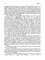
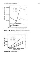
Fig. 2. Simulation Modelling of Vibration Power Generator
Fig. 3. Simulation and Measurement of Output Voltage and Power
The model of the vibration power generator shown in Fig. 2 can be excited
by random vibration or real measured data of vibration. The model of the
Grätz bridge (diode rectifier) and capacitor can be included in this simula-
tion model too. As follows this model can simulate excitation by random
or real vibration and monitor amplitude of the relative movement, rectified
output voltage and actual output power. This process is very useful for de-
sign of optimal generator parameters.
353Simulation of vibration power generator
5. Conclusions
The simulation of the vibration power generator is important for the de-
sign/tuning up of the generator parameters to its exciting vibration. This
generator model is can be used for an optimization and minimization study
too. The advantage of the simulation modeling of vibration power genera-
tor is the possibility to excite it with real vibration data and to monitor the
expected output voltage and power during the excitation. It is very useful
for designing the real product of vibration power generator in dependence
of its vibration environment and output power and voltage requirements.
The power management for stabilization of generated voltage to the re-
quired value can be included in the vibration power generator model. The
waveform of output voltage and power depends on the level of the applied
vibration and the variation of vibration amplitude in time.
The development of the vibration power generator has a great potential as
an inexhaustible source of the electrical energy. The vibration power gen-
erator can provide sufficient electrical energy for some wireless sensors in
aeronautics applications.
Acknowledgement
The results published in this paper have been developed in the frame of the
European FP6 Project “WISE - Integrated Wireless Sensing” (www.wise-
project.org).
Additional subsidization has been received by the Ministry of Education,
Youth and Sports of the Czech Republic, research plan MSM 0021630518
"Simulation Modelling of Mechatronic Systems".
References
[1] Z. Hadaš “Microgenerator – Micromechanical System” PhD. Thesis,
Brno University of Technology, Faculty of Mechanical Engineering, Brno.
[2] Z. Hadaš, V. Singule, Č. Ondrůšek “Overall Tuning up of Vibration
Generator and Choice of Energy Transducer Construction” 5th Interna-
tional Conference on Advanced Engineering Design 2006, Prague, 2006.
[3] V. Singule, Z. Hadaš, Č. Ondrůšek “Analysis of Generic Energy Har-
vesting Vibration Generator” 5th International Conference on Advanced
Engineering Design 2006, Prague, 2006.
354 Z. Hadaš, V. Singule, Č. Ondrůšek, M. Kluge
An Integrated Mechatronics Approach to Ultra-
Precision Devices for Applications in Micro and
Nanotechnology
S. Zelenika (a)
*
, S. Balemi (b)
*
, B. Roncevic (a)
*
(a) University of Rijeka – TFR, Vukovarska 58, 51000 Rijeka, Croatia
(b) SUPSI – DTI, 6928 Lugano-Manno, Switzerland
Abstract
An effort to optimise both mechanical and electronic/control components
of ultra-precision devices is presented. The considered mechanics is
compliant, which overcomes the non-linearities of conventional devices.
Design guidelines for hinge optimisation are given and a preliminary
consideration of the scaling effects is performed. The developed control
system is based on a rapid controller prototyping platform consisting of a
Compact-PCI system running under the Linux RTAI real-time extension.
1. Introduction
Mechatronics is seen as the combination of mechanics, electronics,
computer science and control. The focus of a mechatronics approach lies
on the overall system behaviour, while the different components are seen
as instrumental for obtaining the desired performances. In practice, the fact
that the whole system is as good as its components is often forgotten.
When considering dynamic behaviour as the most important issue, the
impression that the model obtained from the identification procedure is
valid in absolute terms often tends to prevail over the fact that different
working conditions may produce unexpected results.
*
The work was performed within the project "Ultra-high precision compliant devices for
micro and nanotechnology applications" of the Croatian Ministry of Science, Education
and Sports and the project "A stronger Europe with micro and nanotechnologies
(SEMINA)" of the Swiss National Science Foundation.
This work follows an approach aimed at overcoming these limitations via
the optimisation of all system components. The mechatronics device
considered here and shown in Fig.1 is based on optimised compliant
mechanical structures for ultra precision positioning (e.g. for handling and
assembly of microcomponents or for STMs or AFMs). In fact, given the
absence of mechanical non-linearities [1], compliant mechanisms are
advantageous in high precision applications, allowing simple control
typologies to be applied. The architecture of a single degree-of-freedom
(DOF) optimised integrated mechatronics device is hence described.
Fig. 1. Compliant joint and mechatronics device optimised in this work
2. Optimised mechanical structure
Mechanical aspects considered in the design process were the optimisation
of the flexural hinge shapes (Fig. 2) in terms of compliance, strength and
parasitic motions, as well as the scaling effects on the mechanical
properties. Several hinge shapes were considered: the prismatic beam (P
shape), the conventional right circular (RC) hinge, the optimal shapes
obtained in classical mechanics (based on the authors indicated as the
Grodzinski (G), Baud (B) and Thum & Bautz (TB) shape [2]), the
optimised shapes obtained by coupling non-linear parametric optimisation
algorithms with automatic FEM meshing and spline function generators
like the optimised circular shape (OC shape), the optimised pure elliptical
shape (OPE), the elliptical shape with r
y
= h
min
/π (OEB) or the freeform
optimised shape (FFO). Compliances around the primary hinge rotation
DOF
ϕ
z
, as well as the transversal flexural (
ϕ
y
) and axial (x) directions
were taken into account. It was thus established that the FFO and TB
shapes will be the preferred choice when the goal is compliance
θ
θθ
θ
θ
θθ
θ
actuatorcoil-voice
encoder
structurecompliant
x
±
356 S. Zelenika, S. Balemi, B. Roncevic
maximisation along
ϕ
z
(Fig. 3a), while the G, B, OC and OEB shapes will
be preferred when the parasitic shifts and the stress concentration in the
axial and transversal directions are also important (Fig. 3b) [3].
L
L
p
r
x
r
y
h
min
Prismatic
segment
Fillet Fillet
T
x
y
h(x)
A
B
C
O
θ
θθ
θ
h
min
0
e
Thickness b
ϕ
z_
max
C
x
C
T
x
y
Fig. 2. Geometry of flexural hinge and parameterised shape for optimisation
0
2
4
6
8
P
G
B
TB
OC
OPE
OEB
FFO
Hinge shapes
K
σ
σ
σ
σ
, K
C
, K
δ
δ
δ
δ
stress
compliance
parasitic shift
0
1
P
G
B
TB
OC
OPE
OEB
FFO
Hinge shapes
K
σ
σσ
σ
∗
∗∗
∗
L/hmin = 25
L/hmin = 10
L/hmin = 5
(a) (b)
Fig. 3. Hinge behaviour along
ϕ
z (a) and normalized stresses along
ϕ
y (b)
When the considered applications are such that the dimensions of the
mechanical structure must be minimised to nanometric levels, scaling
effects on the entity of the mechanical characteristics must also be taken
into account. In fact, it has been established that in the submicrometric
domain the value of Young’s modulus E can vary up to 70% with respect
to its conventional value [4]. It is also known that the value of the Poisson
coefficient
ν
is seldom known with an accuracy better than 20% [5], but
its estimation at these dimensions has not yet been performed. An
innovative methodology for determining
ν
is thus proposed here. The
method is based on the calculation of the dynamic flexural response of
Euler-Bernoulli-type cantilevers coupled with Von Kármán equations used
to determine the variation of flexural stiffness of rectangular plates. In fact,
the latter is a non-linear function of the deflection of the beam, varying
357An integrated mechatronics approach to ultra-precision devices for applications in
from the value of E for plane strain (small loads) up to E/(1-
ν
2
) for plane
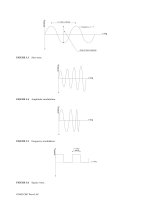
stress (large load) conditions [6]. A seismic excitation of the cantilever
with varying amplitudes will then result in an increment of the flexural
stiffness, and thus of the frequency at which the response amplitude is
maximal (Fig. 4). A suitable dimensioning of the cantilever of known E
allows then a straightforward accurate determination of
ν
.
Fig. 4. Dynamic response of a micrometric silicon cantilever with
ν
= 0.22
3. Actuators and sensors
Various actuating (DC micromotors, stepper motors, voice-coils, PZTs,
inchworms, ultrasonic and inertial actuators) and feedback systems have
been considered for the foreseen applications. Given the needed
resolutions, accuracies and precisions, as well as the needed travel ranges,
power requirements, ease of bidirectional control and large dynamic
ranges, voice-coil actuators have been chosen. On the other hand, high
resolutions and accuracies, excellent dynamic performances, large travel
ranges and an easy integration with the compliant structure made optical
encoders preferential over capacitive sensors, LVDTs and interferometric-
based displacement measurement systems.
4. Control system
The control system is contained in a Compact-PCI rack with a power
supply unit and a standard X86 processor computing board. The system
exploits the results of the RTAI project (www.rtai.org), which offer real-
time extensions of the Linux OS and interfaces with various CACSD tools
(Matlab/Simulink or Scilab/Scicos). Within the same environment a
graphical model can be prepared to feed the process with excitation signals
and to retrieve data for the identification; the real-time application can
send data to a remote PC, where the data is stored, displayed and analyzed.
Frequency ratio
Transmissibilit
358 S. Zelenika, S. Balemi, B. Roncevic
The heart of the control system consists of two specially developed boards:
a sinusoidal encoder signal interpolation board and a driver board for
voice-coil motors. The three channel sinusoidal encoder interpolation
board is built around a commercially available IC and it processes 1 Vpp
sinusoidal signals. It is able to sample the inputs at a frequency of 500 kHz
and to resolve 13 bits within a signal period. The three channel driver
board has an output of up to 3.5 A per channel with a 16 bit resolution.
Other interface boards can be used as well: AD boards for various
measurements or other Compact-PCI compatible boards. Their usage is
immediate if the board is supported by the Comedi project
(www.comedi.org); otherwise the drivers have to be written.
The initial integration of the control system with compliant mechanical
structures allowed excellent performances with high flexibility and
reliability at a limited cost. In fact, nanometric positioning accuracies (less
than 15 nm) have been achieved in millisecond range time spans after a
long (1 mm) range positioning step.
5. Outlook
The improvement in the design of the hinge shapes will be assessed with
experiments. The objective is to accurately determine the stiffness of the
structure as a function of the angle. Intuitively one would measure
statically the dependence between motor currents and the resulting
displacements and obtain the stiffness. However, this dependence is
affected by the position-varying current-to-force characteristics of the
actuator or by deviations due to the sensors’ mounting inaccuracies. The
tests on the structures will thus be based on the analysis of the resonance
frequency at different positions. Precise estimates of the frequencies will
be obtained using periodic excitation signals and the FFT analysis of the
resulting data.
References
[1] L. L. Howell “Compliant Mechanisms” Wiley, New York, 2001.
[2] R. E. Peterson “Stress Concentration Factors” Wiley New York, 1974.
[3] S. Zelenika et al., Proc. 7
th
EUSPEN Int. Conf. (2007).
[4] B. Bhushan (ed.) “Springer Handbook of Nanotechnology” Springer,
Berlin, 2004.
[5] M. J. Madou “Fundamentals of Microfabrication” CRC Press, Boca
Raton, 2002.
[6] P. Angeli et al., Proc. XXXV AIAS Nat. Conf., (2006).
359An integrated mechatronics approach to ultra-precision devices for applications in
Conductive silver thick films filled with carbon
nanotubes
Marcin Sloma (a), Malgorzata Jakubowska (b), Anna Mlozniak (b),
Ryszard Jezior (c)
(a) Warsaw University of Technology, Faculty of Mechatronics, PhD
student, Sw. Andrzeja Boboli 8 street, Warsaw, 02-525, Poland
(b) Institute of Electronic Materials Technology, 133 Wolczynska Street,
Warsaw, 01-919, Poland
(c) Warsaw University of Technology, Institute of Precision and
biomedical Engineering, Division of Precision and Electronic Product
Technology, Sw. Andrzeja Boboli 8 street, Warsaw, 02-525, Poland
Keywords: thick film technology, carbon nanotubes,
Abstract
Search of new, better materials for conductive paste for thick film
compositions deposited by screen printing was the main aim of this work
as well as influence investigations of carbon nanotubes addition to
functional phase of thick film paste. Different types of carbon nanotubes
such as single-walled nanotubes (SWCNT), multi-walled nanotubes
(MWCNT) and non purified non segregated nanotube clusters were mixed
with conductive silver pastes. Obtained mixtures were screen-printed and
fired or cured. The measurements of resistivity were carried out and
changes in resistivity of obtained CNT/silver thick films in comparison to
common silver layer were shown. The influence of different conditions of
firing process were also investigated especially to avoid high temperature
degradation and oxidation of carbon nanotubes. Obtained mixtures with
optimal conductivity will be used for further experiments.
1. Introduction
Recently, carbon nanotubes (CNTs) have been demonstrated to
possess remarkable mechanical and electronic properties, for example in
field emission applications [1,2], chemical sensors [3] or as reinforcing
material in composites [4,5]. CNTs can be synthesized by various methods
such as arc discharge [6], laser vaporization [7] and chemical vapor
deposition (CVD) [8,9]. In this case, purpose of carbon nanotubes addition
is to create active centers in thick film layer, which can be used for
instance as field emission source or adapted to very high frequency radio
communication systems. However, there exists difficulty in fabricating
high quality thick films with proper conductivity and containing
reasonable amount of nanotubes. The paper presents first results of
preparing thick film compositions containing carbon nanotubes. The
authors encountered a lot of difficulties arise during the mixing process of
the compositions Specially prepared thick film composition with selected
nanotube material and silver nanopowder was screen printed and fired to
obtain conductive layer. Direct measurement or conductivity parameter
was carried out in reference to standard silver thick film conductive layer.
2. Materials and preparation
Three types of carbon nanotubes material were taken under
investigation: single-walled nanotubes, multi-walled nanotubes, and
nonsegregated material from synthesis process. The authors found that
SWCNT caused a lot of difficulties in mixing process, and no suitable
thick film composition was obtained. So to minimize time and costs of
experiment, MWCNT material from synthesis was selected for further
experiments. The material was taken directly from synthesis process
without any purification or segregation, so it contained other carbon
nanostructures. However SEM observations of used material showed that
investigated material mostly contained multi-walled carbon nanotubes with
small amount of amourphous carbon and some ferrous grains.
(a) (b)
Fig. 1. SEM images of carbon material: (a) Raw carbon nanotubes material. (b)
The same material after firing in 650
o
C in air, showing ferrous grains and
incineration residues.
361Conductive silver thick lms lled with carbon nanotubes
Estimated mean dimension of nanotoubes was approximately 50nm in
diameter and 1000-2000nm in length. Ferrous grains were estimated to be
in size under 1000nm and were only observed after additional firing
process in 650
o
C after degradation of nanotubes and other carbon
structures.
Silver nanopowder used for Ag-CNT composition was obtained by
chemical precipitation process by the authors and it was classified to be in
range of 100-300nm dimensions with some addition of larger grains.
(a) (b)
Fig. 2. SEM images of Ag nanopowder used for Ag-CNT composition (a) and Ag-
CNT mixture (b).
As reference, standard silver thick film paste P-120 (ITME) was used, to
prepare screen printed and fired conductive layer.
Compositions of nanomaterials were fabricated in specially
adapted ultrasonic stirring process to obtain homogeneous mixture, which
is essential to obtain well produced thick film layer with appropriate
electric parameters. Two kinds of Ag-CNT compositions were prepared,
regarding firing process. The compositions contained differend organic
resins suitable for firing process conducted in air atmosphere
(ethylcellulose resin) and for firing in protective nitrogen atmosphere
(acrylate resin). Compositions were screen printed on alumina substrates in
adequate pattern. Firing process for standard silver paste was conducted in
650
o
C in air, and for Ag-CNT pastes in 470
o
C in air and 650
o
C in N
2
respectively.
3. Results and discussion
Obtained thick film layers were well sintered in both cases with
better results form specimen fired with higher temperature in nitrogene.
Tracks fabricated from Ag-CNT material were practically
indistinguishable from each other, whats proofs good selection of materials
conducted at early stage. Unfortunately, against assumptions there where
362 M. Sloma, M. Jakubowska, A. Mlozniak, R. Jezior
no nanotubes observed at surface of sintered layer. In spite of many
observations it was impossible to detect them in any sample or region. It
was caused by low amount of nanotubes in thick film composition. Only
observations of scrapped away layer revealed that carbon nanotubes
unmodified by the firring but hidden beneath main silver layer.
Fig. 3. SEM images of fired Ag-CNT layer, top view (on left), bottom view
“scrapped away” (on right)
Resistance measurement was conducted with Keithley multimeter
2001 for both examined samples and for reference sample on the same
length pattern, which allows to directly compare obtained parameters.
Fig. 4. Pattern of measured samples (drawing and object picture)
Obtained values of resistances for Ag-CNT compositions are varied from
resistance for standard Ag thick film layer, but differences are not so
significant. Main reason for that is that fabrication and firing processes are
not yet optimal, and obtained layers are not ideal. But for instance taking
under consideration very low temperature applied for air firing process,
this layer have very fair conductivity and N
2
fired layer is in the same
order of magnitude.
Ag 650
o
C air Ag-CNT 470
o
C air Ag-CNT 650
o
C N
2
R [ohms] 0,4 1,8 0,8
Fig. 5. Comparison of measured resistances for examined samples
363Conductive silver thick lms lled with carbon nanotubes
This results will be utilized in the further step of experiments where goal is
to obtain thick film specimens with carbon nanotubes placed on surface of
the layer.
4. Conclusion
One of the key issues in the development of thick film materials
containing nanomaterials such as carbon nanotubes is controlling
agglomeration process and aim for homogeneous mixture. It is crucial for
obtaining well sintered layer which allows to gain proper electric
parameters. The results presented in this paper demonstrate that specific
selection of materials and fabrication procedures allows to overcome many
inconveniences both during process and in resulted properties. Examined
samples represented them selfs as very promising materials. Both layers
have very fair conductivity which can be improved by optimization stirring
and firing processes. After some major improvements materials will be
used for further studies.
References
[1] T-Y Tsai, N-H Tai, I-N Lin “Characteristics of carbon nanotube electron field
emission devices prepared by LTCC process”, Diamond and Related
Materials 13 (2004) 982–986
[2] N.S. Lee, D.S. Chung, I.T. Han, J.H. Kang, Y.S. Choi, H.Y. Kim, S.H. Park,
Y.W. Jin, W.K. Yi, M.J. Yun, J.E. Jung, C.J. Lee, J.H, You,
S.H. Jo, C.G. Lee, J.M. Kimb “Application of carbon nanotubes to field
emission displays”, Diamond and Related Materials 10 (2001) 265-270
[3] Kunjal Parikh, Kyle Cattanach, Rashmi Rao, Dong-Seok Suh,
Aimei Wu, Sanjeev K. Manohar “Flexible vapour sensors using single walled
carbon nanotubes”, Sensors and Actuators B 113 (2006) 55–63
[4] A. Esawi, K. Morsi “Dispersion of carbon nanotubes (CNTs) in aluminum
powder”, Composites: Part A 38 (2007) 646–650
[5] A.R. Boccaccini, D.R. Acevedo, G. Brusatin, P. Colombo “Borosilicate glass
matrix composites containing multi-wall carbon nanotubes”, Journal of the
European Ceramic Society 25 (2005) 1515–1523
[6] T.W. Ebbesen, P.M. Ajayan, Nature 358 (1992) 220
[7] A. Thess, R. Lee, P. Nikolaev, H. Dai, P. Petit, J. Robalt, et al., Science 273
(1996) 483.
[8] W.Z. Li, S.S. Xie, L.X. Qain, B.H. Chang, B.S. Zou, W.Y. Zhou, et al.,
Science 274 (1996) 1701.
[9] Z.W. Pan, S.S. Xie, B.H. Chang, L.F. Sun, W.Y. Zhou, G. Wang, Chem. Phys.
Lett. 299 (1999) 97.
364 M. Sloma, M. Jakubowska, A.Mlozniak, R. Jezior
Perspectives of applications of micro-machining
utilizing water jet guided laser.
Z. Sokołowski, I. Malinowski
Warsaw University of Technology,
Institute of Precision and Biomedical Engineering
Św.A. Boboli 8, 02-525 Warszawa, Poland, ,
Abstract
The machining using laser energy stream concentrated within the water jet,
having a length of several centimeters and the width comparable with the
size of focus in traditional methods of machining, gives the ability of
working on three dimensional, spatial elements. The cooling effect of wa-
ter and its participation in removing the debris material, allow for attaining
significantly higher quality of the work-piece surface and minimizes the
harmful impact on environment and work safety. The capabilities of this
method open for it applications, in which the traditional method of laser
machining does not prove itself valid. In the article given is the principle
of the method and the examples of its implementation. Determined are at-
tained parameters of machining for various materials: silicon, gallium ar-
senide, ferrites, acid resistant steels, super hard materials. Given also are
examples of application water jet guided laser machining in manufacturing
technology of mechatronics.
1.The idea of laser machining in water jet.
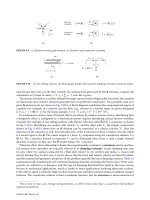
General scheme of the laser beam concentrated in water jet is shown on the
figure 6. Under pressure p the water flow out from the nozzle with velocity
V. For small values of the diameter (d = 50…150 µm) and pressure
>1MPa the typical equations of fluid mechanics need some corrections,
however the water velocity V can be expressed as:
ρ
p
V
2
≈
,
where ρ is the water density (1)
Fig. 1. a) Laser beam concentrated in water jet , where α is the angle of total
internal reflection, b) the line work segment of laminar flow .
Water jet guided laser is a technique utilizing delivery of laser beam via
total internal reflection of laser beam in water. This technique produces a
water jet containing internally reflected and guided laser beam, which can
be utilized for variety of purposes. The great advantages of water jet
guided laser are:
1. Ability to maintain uniform beam width on a prolonged distance
(approx 1000 times water-laser beam width) without divergence
2. Lack or minimum of thermal damage to cut material due to effi-
cient cooling simultaneous with the laser ablation- “cold laser” –
produces highly biocompatible cuts
3. Lack or minimum of impurities generated in water-laser jet proc-
ess due to efficient material removal with water (efficient washing
out of molten material)
4. Ability to produce high quality cuts or trenches with parallel walls,
and of any shape
5. Minimum force exerted by water jet (approx 0.03-0.1 N)
6. Ability to utilize variety of laser wavelengths – most popular 1064
nm, (best results for green lasers such as Nd:YAG at 532 nm
wavelength –where water absorption is minimum)
7. Ability to stop the laser light sideways movement with respect to
work material without continued ablation – no need to retract or
withdraw the beam
8. Small cutting radius (14 µm) and fine tolerance (1-3µm)
9. No burrs in the cut zone, no charring or contamination
10. No recrystallization, oxidation or micro cracks. Additionally the
material is not distorting or warping. The tolerances of the final
products are very small
2
α
d
a)
b)
366 Z. Sokołowski, I. Malinowski
11. Multi-layer, super-hard materials such as CBN (cubic boron ni-
tride), PCD (polycrystalline diamond), PCBN (polycrystalline cu-
bic boron nitride), or silicon nitride and porous material can be cut
The above advantages of water jet guided laser have caused it to be applied
in medical device manufacturing [1], [2], [3]. Blades, scalpels, micro-
tubes, stents and chips can be made using water jet guided laser machin-
ing.
Blades or scalpels are mainly used in surgical operations; they are also
used by dentists, veterinary surgeons as well as by professionals in some
other industries. A large amount of blades are produced for different appli-
cations. Blades are frequently made of steel, carbon steel, tungsten carbide,
ceramics or silicon can be produced with a perfect cutting edge in spite of
the complexity of the shapes and very economically . The main manufac-
turing tasks are: cutting out of slots, cutting of complex shapes, edging,
drilling and grinding.
Tubes include a large array of devices such as cannulae, needles, or endo-
scopes. They are usually used for intra vascular operations so they tend to
be less traumatic and more minimally invasive. Tubes are normally made
of steel, stainless steel, titanium, or nitinol (NiTi). The main manufacturing
tasks are: cutting out of slots, complex cutting, micro drilling of holes,
edging. Tube wall thickness usually varies from 30 µm to 600 µm and re-
quire and excellent surface finish.
Microchips are integrated in sensors, transducers, pacemakers, auditory
devices, or flex circuits. They use chips that have to be manufactured (e.g.
wafer dicing, singulation). Wafers are typically made of silicon and their
thickness vary from 20 to 1500 microns. The main manufacturing tasks
are: wafer processing includes a large array of applications such as slicing,
dicing, cutting edges, grinding, slotting and drilling. Multi-project wafers
can be manufactrured. Complex shapes and grooves in PZT (piezoelectric
ceramics) can be made using water jet guided laser for use in medical ul-
trasonics. Ferrite cores can be cut with uniform gap width (15µm wider
than the width of water jet) for use in electronic circuits and advanced
medical devices.
Cutting of medical stents Stents are used in medicine to open up, and
maintain patent, congested blood vessels. They support and dilate the ves-
sels’ tissue and allow unimpeded blood flow. Usually they are made out of
stainless steel or nickel-titanium. The contours, which have to be cut in
these thin tubes, are very small and complex. Up to recently mostly classi-
cal laser cutting or chemical etching have been used. Classical laser cutting
of stents however requires important post treatment by mechanical and
367Perspectives of applications of micro-machining utilizing water jet guided laser
chemical cleaning and polishing steps. The water jet guided laser inhibi-
material changes – an important property for this application as product
failure may be harmful to patient. The Laser Microjet cut stent-tubes are
already sufficiently clean that the post treatment steps can be considerably
shortened (see Figure 2).
Fig. 2. 200 µm thick and 120 µm width Nitinol stent cut with the Laser Microjet
(no further process)
The small radius of only 14 microns enables fine contours. Cutting speeds
of more than 12 mm/s allow high throughput. The important advantages of
the water jet guided laser in this application are: no heat influence, small
beam radius, high speed, the smallest forces as well as the absence of con-
tamination. The water jet guided laser is well adapted to medical devices;
it can cut, drill, groove, mark, scribe or dice with a high degree of preci-
sion, speed, cleanliness and reliability. The problems related to heat dam-
age, post-treatment, debris, deposition, or focal point, are totally removed.
The future applications of water jet guided laser may include its wide use
in biomedical engineering, as a surgical tool or technology for manufactur-
ing of medical device elements.
Technical data of water jet process:
Wavelength: 1064 or 532 nm (solid state)
Pulse rep. rate: 25 kHz; 1000 Hz
Pulse duration: 200 – 600 ns; 50 – 250 s
Max. laser power: 120 W; 300 W
Water jet pressure: 50 – 500 bar
Water jet diameter 30 – 150 m
Water quality: filtered to 0.2 m, de-ionized
Water jet length: 50 mm
368 Z. Sokołowski, I. Malinowski