The MEMS Handbook (1st Ed) - M. Gad el Hak Part 4 pdf
Bạn đang xem bản rút gọn của tài liệu. Xem và tải ngay bản đầy đủ của tài liệu tại đây (957.52 KB, 5 trang )
© 2002 by CRC Press LLC
Two options exist: (1) hydrostatic (externally pressured) thrust bearings, in which the fluid is fed from
a high-pressure source to a lubrication film, and (2) hydrodynamic, where the supporting pressure is
generated by a viscous pump fabricated on the surface of the thrust bearing itself (see Figure 9.9). Hydrostatic
bearings are easy to operate and relatively easy to fabricate. These have been successfully demonstrated in
the MIT Microengine program [Fréchette et al., 2000]; the thrust bearing is shown in Figure 9.8, which
shows an SEM of the fabricated device cut though the middle to reveal the plenum, restrictor holes and
bearing lubrication gap, which is approximately 1
µm wide. Key to the successful operation of hydrostatic
FIGURE 9.8 Close-up cutaway view of microthrust bearing showing the pressure plenum (on top), feed holes and
bearing gap (faintly visible). (SEM courtesy of C C. Lin.)
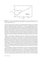
FIGURE 9.9 Schematic of hydrodynamic thrust bearings and predicted performance (stiffness, in N/m, vs. axial
eccentricity) for a typical spiral-groove thrust bearing for use in a high-speed MEMS rotor.
High pressure plenum
(pumped up by spiral grooves)
Inward-pumping
spiral grooves
Rotor
Stator
Axis of rotation
1.50E+06
1.30E+06
1.10E+06
9.00E+05
7.00E+05
5.00E+05
Eccentricity
-0.45
-0.3
-0.15
0
0.15
0.3
0.45
© 2002 by CRC Press LLC
Two options exist: (1) hydrostatic (externally pressured) thrust bearings, in which the fluid is fed from
a high-pressure source to a lubrication film, and (2) hydrodynamic, where the supporting pressure is
generated by a viscous pump fabricated on the surface of the thrust bearing itself (see Figure 9.9). Hydrostatic
bearings are easy to operate and relatively easy to fabricate. These have been successfully demonstrated in
the MIT Microengine program [Fréchette et al., 2000]; the thrust bearing is shown in Figure 9.8, which
shows an SEM of the fabricated device cut though the middle to reveal the plenum, restrictor holes and
bearing lubrication gap, which is approximately 1
µm wide. Key to the successful operation of hydrostatic
FIGURE 9.8 Close-up cutaway view of microthrust bearing showing the pressure plenum (on top), feed holes and
bearing gap (faintly visible). (SEM courtesy of C C. Lin.)
FIGURE 9.9 Schematic of hydrodynamic thrust bearings and predicted performance (stiffness, in N/m, vs. axial
eccentricity) for a typical spiral-groove thrust bearing for use in a high-speed MEMS rotor.
High pressure plenum
(pumped up by spiral grooves)
Inward-pumping
spiral grooves
Rotor
Stator
Axis of rotation
1.50E+06
1.30E+06
1.10E+06
9.00E+05
7.00E+05
5.00E+05
Eccentricity
-0.45
-0.3
-0.15
0
0.15
0.3
0.45
© 2002 by CRC Press LLC
10
Physics of Thin
Liquid Films
10.1 Introduction
10.2 The Evolution Equation for a Liquid Film
on a Solid Surface
10.3 Isothermal Films
Constant Surface Tension and Gravity • van der Waals
Forces and Constant Surface Tension • Homogeneous
Substrates • Heterogeneous Substrates • Flow on a
Rotating Disc
10.4 Thermal Effects
Thermocapillarity, Surface Tension and Gravity • Liquid Film
on a Thick Substrate
10.5 Change of Phase: Evaporation and Condensation
Interfacial Conditions • Evaporation/Condensation
Only • Evaporation/Condensation, Vapor Recoil, Capillarity
and Thermocapillarity • Flow on a Rotating Disc
10.6 Closing Remarks
Acknowledgments
10.1 Introduction
Various aspects of fluid mechanics in microelectromechanical systems (MEMS), such as flows in micro-
configurations, flow transducers and flow control by microsystems, were reviewed by Ho and Tai (1998).
However, the issue of thin liquid films and their dynamics in the context of microelectromechanical
systems was left out of the scope of that important work. This chapter is intended to fill this gap.
Thin liquid films are encountered in a variety of phenomena and technological applications [Myers,
1998]. On a large scale, they emerge in geophysics as gravity currents under water or as lava flows [Huppert
and Simpson, 1980; Huppert, 1982]. On the engineering scale, liquid films serve in heat and mass transfer
processes to control fluxes and protect surfaces, and their various applications arise in paints, coatings
and adhesives. They also occur in foams [Schramm, 1994; Prud’homme and Khan, 1996], emulsions
[Ivanov, 1988; Edwards et al., 1991] and detergents [Adamson, 1990]. In biological applications, they
appear as membranes, as linings of mammalian lungs [Grotberg, 1994] or as tear films in the eye [Sharma
and Ruckenstein, 1986]. On the microscale in MEMS, thin liquid films are used to produce an insulating
coating of solid surfaces, to form stable liquid bridges at specified locations, to create networks of
microchannels on patterned microchips [Herminghaus et al., 1999; 2000] and to design fluid microre-
actors [Ichimura et al., 2000].
The presence of the deformable interface between the liquid and the ambient (normally gaseous, but
possibly also another liquid) phases engenders various kinds of dynamics driven by one or usually several
physical factors simultaneously. Liquid films may spontaneously or under the influence of external factors
Alexander Oron
Technion–Israel Institute of
Technology
© 2002 by CRC Press LLC
11
Bubble/Drop Transport
in Microchannels
11.1 Introduction
11.2 Fundamentals
11.3 The Bretherton Problem for Pressure-Driven
Bubble/Drop Transport
Corrections to the Bretherton Results for Pressure-Driven Flow
11.4 Bubble Transport by Electrokinetic Flow
11.5 Future Directions
Acknowledgments
11.1 Introduction
Many microdevices involve fluid flows. Microducts, micronozzles, micropumps, microturbines and
microvalves are examples of small devices with gas or liquid flow. It would be extremely desirable to
design similar devices for two-phase flows, and many attractive applications can be envisioned if microre-
actors and microlaboratories could include immiscible liquid–liquid and gas–liquid systems. Miniature
evaporative and distillation units, bubble generators, multiphase extraction/separation units and many
other conventional multiphase chemical processes could then be fabricated at microscales. Efficient
multiphase heat exchangers could be designed for MEM devices to minimize Joule or frictional heating
effects. Even for the current generation of microlaboratories using electrokinetic flow, multiphase flow
has many advantages. Drops of organic samples could be transported by flowing electrolytes, thus extending
the electrokinetic concept to a broader class of samples. Gas bubbles could be used as spacers for samples
in a channel or to act as a piston to produce pressure-driven flow on top of the electrokinetic flow. Flow
valves and pumps that employ air bubbles, like those in the ink reservoirs of ink jet printers, are already
being tested for microchannels. Drug-delivery and diagnostic devices involving colloids, molecules and
biological cells are also active areas of research.
Before multiphase flow in microchannels becomes a reality, however, several fundamental problems
that arise from the small dimension of the channels must be solved. Most of these problems originate
from the large curvature of the interface between two phases in these small channels. As a result, capillary
effects and other related phenomena dominate in multiphase microfluidics. Contact-line resistance, for
example, is often negligible in macroscopic flows. The contact-line region, defined by intermolecular and
capillary forces, is small compared to the macroscopic length scales. However, in microchannels, the
contact-line region is comparable in dimension to the channel size. As a result, the large stress in that
region (the classical contact-line logarithm stress singularity) can dominate the total viscous dissipation
[Kalliadasis and Chang, 1994; Veretennikov et al., 1998; Indeikina and Chang, 1999]; hence, it is inad-
visable to have contact lines in microchannels unless one is prepared to apply enormous pressure or
electric potential driving forces. One fluid should wet the channel or capillary walls while the other is
Hsueh-Chia Chang
University of Notre Dame
© 2002 by CRC Press LLC
12
Fundamentals of
Control Theory
12.1 Introduction
12.2 Classical Linear Control
Mathematical Preliminaries • Control System Analysis and
Design • Other Topics
12.3 “Modern” Control
Pole Placement • The Linear Quadratic Regulator • Basic
Robust Control
12.4 Nonlinear Control
SISO Feedback Linearization • MIMO Full-State Feedback
Linearization • Control Applications of Lyapunov Stability
Theory • Hybrid Systems
12.5 Parting Remarks
12.1 Introduction
This chapter reviews the fundamentals of linear and nonlinear control. This topic is particularly important
in microelectromechanical systems (MEMS) applications for two reasons. First, as electromechanical
systems, MEMS devices often must be controlled in order to be utilized in an effective manner. Second,
important applications of MEMS technology are controls-related because of the utility of MEMS devices
in sensor and actuator technologies. Because the area of control is far too vast to be entirely presented in
one self-contained chapter, the approach adopted for this chapter is to outline a variety of techniques
used for control system synthesis and analysis, provide at least a brief description of their mathematical
foundation, discuss the advantages and disadvantages of each of the techniques and provide sufficient
references so that the reader can find a starting point in the literature to fully implement any described
techniques. The material varies from the extremely basic (e.g., root locus design) to relatively advanced
material (e.g., sliding mode control) to cutting-edge research (hybrid systems). Some examples are
provided; additionally, many references to the literature are provided to help the reader find further examples
of a particular analysis or synthesis technique.
This chapter is divided into three sections, each of which considers both the stability and performance
of a control system. The term
performance
includes both the qualitative nature of any transient response of
the system, reference signal tracking properties of the system and the long-term or steady-state perfor-
mance of the system. The first section considers “classical control,” which is the study of single-input,
single-output (SISO) linear control systems, which relies heavily upon mathematical techniques from
complex variable theory. The material in this section outlines what is typically covered in an elementary
undergraduate controls course. The second section considers so-called “modern control” which is the
study of multi-input, multi-output (MIMO) control systems in state space. Included in this section is
Bill Goodwine
University of Notre Dame